The present invention relates to an apparatus for
executing executable code such as an encoded program,
etc., and a method for distributing such executable
code. Such code (which may contain many individual
instructions or functions) will be referred to as
"a code" below.
An environment in which only an authenticated code
is operated can be realized by executing an executable
code (hereinafter referred to simply as a code), which
contains an electronic signature and is encrypted. An
executable code includes a part or all of an encoded
program. Amethod for realizing such an environment can
be that of assuming a processor (secure processor)
having the function of verifying a signature and the
function of decrypting data as a memory-mapped
input/output device (I/O device). In this method, an
encrypted code is transmitted as data to the I/O device,
executes the code, and obtains an execution result.
However, there is the following problem with the
conventional code executing method.
In this code executing method, a large code cannot
be entirely passed at a time because the memory capacity
of an I/O device is limited. In addition, if execution
is started with a code first passed, other controlling
processes cannot be performed until the execution is
completed. Therefore, a signature verifying process,
a secure decrypting process, etc. cannot be performed
in a multitasking mode. As a result, a plurality of
tasks accompanied by a secure process cannot be
efficiently performed.
The latter problem can be solved by designing an
I/O device such that a multitasking operation can be
performed, and providing a task management module
exclusively for the I/O device in the operating system
(OS). However, the OS is provided with both the task
management module exclusive for an I/O device (secure
processor) and a task management module for a normal
processor, which is not desirable for the efficiency.
Furthermore, from the viewpoint of security, it
is desired that the OS itself is operated in a secure
processor, but the existing OS cannot be easily
rewritten for use with the secure processor.
The present invention aims at providing an
apparatus for efficiently executing encrypted code
containing an electronic signature without greatly
changing the existing OS, and a method for distributing
code to the apparatus.
The code execution apparatus according to the
present invention is realized through a multiprocessor
system, and includes a secure memory, a secure processor,
a normal memory, a normal processor, and a controller.
The secure memory stores the encrypted code of a
secure task, and verifying information for verifying
the validity of the encrypted code. The secure
processor executes the encrypted code if the verifying
information verifies the validity of the encrypted code.
The normal memory stores code of the normal task, and
the normal processor executes the code of the normal
task.
The controller allocates the secure task and the
normal task, stores the encrypted code in the secure
memory, and stores the code of the normal task in the
normal memory.
A code distributing method for the code execution
apparatus can be any of the following two methods.
Reference is made, by way of example, to the
accompanying drawings in which:
The embodiments of the present invention are
described below in detail by referring to the attached
drawings.
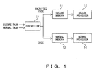
FIG. 1 shows the principle of the code execution
apparatus according to the present invention. The code
execution apparatus shown in FIG. 1 is realized through
a multiprocessor system, and comprises a secure memory
11, a secure processor 12, a normal memory 13, a normal
processor 14, and a controller 15.
The secure memory 11 stores an encrypted code of
a secure task, and verifying information for
verification of the validity of the encrypted code. The
secure processor 12 executes an encrypted code when the
verifying information verifies the validity of the
encrypted code. The normal memory 13 stores the code
of a normal task, and the normal processor 14 executes
the code of a normal task.
The controller 15 allocates a secure task and a
normal task, and stores an encrypted code in the secure
memory 11, and stores the code of a normal task in the
normal memory 13.
Verifying information can be, for example, an
electronic signature, a parity code, a CRC (cyclic
redundancy check) bit, etc. The controller 15
corresponds to, for example, the OS of a multiprocessor
system.
When a secure task is executed, the controller 15
stores the encrypted code and the verifying information
in the secure memory 11. If the validity of the
encrypted code is verified according to the verifying
information, the secure processor 12 executes the
encrypted code.
When the normal task is executed, the controller
15 stores the code in the normal memory 13, and the normal
processor 14 executes the code.
Thus, the task management can be easily performed
by allowing a secure task and a normal task to co-exist
in the multiprocessor system, and by the controller 15
allocating the tasks to the secure processor 12 and the
normal processor 14. Therefore, the code of a secure
task can be efficiently performed without greatly
changing the OS.
There can be two methods of distributing a code
to the multiprocessor system as follows.
According to the present embodiment, a processor
in the multiprocessor system is replaced with a secure
processor, thereby generating a heterogeneous
multiprocessor. Then, the OS controls the allocation
of a secure task and an unsecured task to each processor.
Thus, by generating a heterogeneous multiprocessor
including a secure processor, the OS does not need to
have double task management modules.
Furthermore, by allowing a secure task and an
unsecured task to co-exist, a migration can be realized
such that the tasks are changed to secure tasks step
by step from a possible one, thereby finally securing
the entire tasks of the OS. Although such a migration
is limited to the case where the OS is realized as a
set of small tasks, it is not necessary to rewrite an
existing OS directly for a secure processor in the
migration.
However, in the above mentioned system, a secure
processor fetches and executes an encrypted code in
units of an instruction. Therefore, an entire code
cannot be collectively passed to the secure processor,
and if a signature is added to the entire encrypted code,
the signature cannot be verified. In the present
embodiment, an encrypted code is generated by assigning
a signature in units of a page (for example, every 4K
bytes, etc.), which is the minimum unit for memory
allocation, and the memory itself verifies the signature
when the memory allocation is performed.
Then, an organization for collecting the codes to
be distributed to the system, and assigning signatures
to the collected codes is provided. The code generator
can widely distribute code, and the user can safely use
the codes.
FIG. 2 shows the configuration of the
multiprocessor system. The system shown in FIG. 2
comprises a normal memory 21, a normal processor 22,
a secure memory 23, a secure processor 24, and a secure
drive/medium 25. These units are interconnected
through a system bus 26, but the normal processor 22
does not fetch an instruction from the secure memory
23, and the secure processor 24 does not fetch an
instruction from the normal memory 21.
The normal processor 22 executes a normal code of
a normal task (unsecured task) using the normal memory
21, and the secure processor 24 executes an encrypted
code of a secure task using the secure memory 23. The
secure drive/medium 25 is a storage device for storing
an encrypted code for a secure task. In FIG. 2, a normal
processor 22 and a secure processor 24 are provided,
but a plurality of normal and secure processors can also
be provided.
FIG. 3 shows an example of the configuration of
the secure memory 23 and the secure processor 24. The
secure memory 23 shown in FIG. 3 comprises a certificate
authority public key 31, a signature verification unit
32, a signature holding unit 33, and a page 34. The page
34 is the minimum unit for allocation of physical memory
(real memory), and has the capacity of, for example,
4 Kbytes. The signature holding unit 33 has an area
storing signature data for each page. The signature
verification unit 32 is installed through, for example,
hardware or an MPU (micro processing unit), and an
encrypted code is verified in units of a page using a
signature.
The signature corresponds to, for example, an X.
509 certificate which is generated by a secret key of
a certificate authority (CA) and can be verified by a
public key of the CA stored in advance in the secure
memory 23.
The secure processor 24 comprises a decryption key
setting unit 41, a decryption key holding unit 42, a
decryption unit 43, and a processor 44. Among these
units, the decryption key setting unit 41, the
decryption key holding unit 42, and the decryption unit
43 are provided in front of an instruction input unit
of the processor 44 for executing an instruction, and
the decryption unit 43 is implemented through, for
example, hardware or an MPU.
An encrypted code containing a signature is read
by the secure drive/medium 25, divided into a signature
and an encrypted code, which are respectively stored
in the signature holding unit 33 and the page 34.
When they are stored, the signature verification
unit 32 verifies the signature using the public key of
the certificate authority which generated the signature.
If there is no problem, the hash value of the encrypted
code contained in the signature is compared with the
hash value computed again from the encrypted code on
the page 34.
If these hash values match each other, and it is
checked that the encrypted code has not been forged,
then the secure processor 24 is notified that the
encrypted code on the page 34 is valid (valid code).
If the hash values do not match each other, then the
secure processor 24 is notified that the encrypted code
on the page 34 is invalid (invalid code).
Upon receipt of a validity notification, the
decryption unit 43 of the secure processor 24 fetches
a necessary encrypted instruction at the memory address
on the page 34, and sequentially decrypts encrypted
instructions using the decryption key of the decryption
key holding unit 42. Then, the processor 44
sequentially executes the decrypted instructions. The
decryption key required to decrypt instructions is set
in the decryption key holding unit 42 in advance.
Furthermore, a plurality of decryption keys can
be stored in the secure processor 24 to externally
specify which decryption key is to be used in decrypting
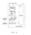
an instruction. FIG. 4 shows the configuration of the
secure processor 24.
The secure processor 24 shown in FIG. 4 is
different from the secure processor 24 shown in FIG.
3 in that a plurality of decryption key holding units
42 are provided, and a decryption key indicating unit
45 indicating which of a plurality of decryption keys
stored in these decryption key holding units 42 is to
be used is added. The decryption key indicating unit
45 can be implemented through, for example, hardware
or an MPU. The OS instructs the decryption key
indicating unit 45 which decryption key is to be used
depending on the secure task being executed.
FIG. 5 shows the configuration of the secure OS
for controlling the operation of the multiprocessor
system shown in FIG. 2. A secure OS 51 shown in FIG.
5 is operated in the secure processor 24 and/or the
normal processor 22, and comprises a secure task
management 52, a secure memory management 53, and a
secure file system 54.
The secure task management 52 and the secure
memory management 53 allocate secure tasks and unsecured
tasks. Therefore, the encrypted codes of the secure
tasks are stored in the secure memory 23, and the codes
of the unsecured tasks are stored in the normal memory
21. The secure task management 52 controls the
multitask processes of both secure tasks and unsecured
tasks. Described below is the operation performed when
a target task is a secure task.
The secure task management 52 manages the context
of a plurality of tasks. When the context is switched,
it performs normal processes such as changing the
program counter of the secure processor 24, etc., and
specifies which of the decryption keys held in the secure
processor 24 is to be used.
The secure memory management 53 allocates the
secure memory 23 to a secure task as necessary. An
encrypted instruction is transferred from the secure
memory 23 to the secure processor 24 without passing
through the secure memory management 53 because this
is a fetching operation of the CPU (central processing
unit).
The secure file system 54 manages files of
encrypted codes stored in the secure drive/medium 25.
At a request of the secure memory management 53, an
encrypted code is read from the secure drive/medium 25
and passed to the secure memory management 53 by the
secure file system 54.
The processes of the secure task management 52,
the secure memory management 53, and the secure file
system 54 are described in detail by referring to FIGS.
6 through 9.
FIG. 6 is a flowchart of the process of the secure
task management 52. The process shown in FIG. 6 is
started when the time slice of the secure task being
performed in the secure processor 24 is up, a timer
interruption occurs, and control is passed to the secure
task management 52.
The secure task management 52 first determines a
secure task A to be executed next according to the
scheduling algorithm (step S1), and restores the context
of the secure task A (step S2). At this time, the program
counter and the stack pointer of the secure processor
24 are restored, and the TLB (translation look-aside
buffer) in the MMU (memory management unit) existing
between the secure processor 24 and the secure memory
23 is restored, etc.
Then, the secure processor 24 is instructed to use
a program decryption key for a secure task A (step S3).
The time slice (for example, 100 ms) of the secure task
A is set on the timer (step S4), and the operation of
the secure processor 24 is resumed (step S5).
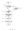
FIG. 7 is a flowchart of the process of the secure
memory management 53. The process shown in FIG. 7 is
started when a page fault occurs during the execution
of a secure task, an interruption occurs, and control
is passed to the secure memory management 53.
The secure memory management 53 first checks
whether or not an unused real memory area exists in the
secure memory 23 (step S11). If there is a real memory
area, one page is allocated (step S13). If there is no
unused real memory area, a subroutine of performing a
memory releasing process is invoked (step S12), a space
is reserved, and a real memory area is allocated.
Then, a correspondence table between an allocated
real memory address and a virtual address is generated,
and stored in the TLB in the MMU (step S14). A request
for a code for assignment in the allocated real memory
is issued to the secure file system 54, a received code
is assigned to the real memory (step S15), and the
operation of the secure processor 24 is resumed (step
S16).
FIG. 8 is a flowchart of the real memory releasing
process performed by the subroutine invoked in step S12
shown in FIG. 7. The subroutine first determines the
target real memory area for page-out according to the
real memory releasing algorithm (step S21). Then, the
code in the target real memory area is paged out
(written) to the secure drive/medium 25 (step S22).
Then, control is returned to the calling program (step
S23).
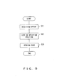
FIG. 9 is a flowchart of the process of the secure
file system 54. The process in FIG. 9 is started when
a request for a code is issued by the secure memory
management 53 in step S15 shown in FIG. 7.
The secure file system 54 first receives the
offset from the beginning of a target program (step S31),
and seeks up to the specified position in the secure
drive/medium 25 (step S32). Then, a code of 1 page is
read from the specified position, and passed to the
secure memory management 53 (step S33).
It is also possible to safely communicate an
encrypted code by the secure memory 23 and the secure
processor 24 authenticating each other to share a
session key. In this case, the secure memory 23 further
encrypts the encrypted code using a session key, and
transfers it to the secure processor 24.
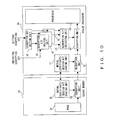
FIG. 10 shows the configuration of such a secure
memory 23 and a secure processor 24. The secure memory
23 shown in FIG. 10 further comprises a mutual
certificate/session key sharing unit 61 and an
encryption unit 62 in addition to the configuration
shown in FIG. 3, and the secure processor 24 further
comprises a mutual certificate/session key sharing unit
71 and a decryption unit 72 in addition to the
configuration shown in FIG. 4.
First, the mutual certificate/session key sharing
unit 61 and the mutual certificate/session key sharing
unit 71 authenticate each other as a mutually reliable
party, and generate and share a session key. The method
of authenticating each other can be either a method based
on a certificate using a public key, or a method using
a common key. A session key is generated using, for
example, a random number.
Then, the encryption unit 62 of the secure memory
23 further encrypts the encrypted instruction on the
page 34 using a session key, and transfers it to the
secure processor 24. The decryption unit 72 of the
secure processor 24 decrypts the received encrypted
instruction using a session key, and passes it to the
decryption unit 43. Then, as shown in FIG. 4, the
encrypted instruction is decrypted by a corresponding
decryption key, and is then executed.
Similarly, the secure drive/medium 25 and the
secure memory 23 authenticate each other to share a
session key, thereby safely communicating an encrypted
code.
FIG. 11 shows the configuration of such a secure
drive/medium 25 and a secure memory 23. The secure
drive/medium 25 shown in FIG. 11 comprises a storage
medium 81, a storage device unique key 82, a mutual
certificate/session key sharing unit 83, a decryption
unit 84, and an encryption unit 85. The secure memory
23 further comprises a decryption unit 63 in addition
to the configuration shown in FIG. 10.
The secure drive/medium 25 further encrypts the
encrypted code using the storage device unique key 82
or the storage medium unique key 86, and stores it in
the storage medium 81. The storage medium 81 can be a
magnetic disk, an optical disk, a magneto-optical disk,
a magnetic tape, etc. The storage device unique key 82
is a key unique to the secure drive/medium 25, and a
storage medium unique key 86 is a key unique to the
storage medium 81.
As in the case shown in FIG. 10, the mutual
certificate/session key sharing unit 83 and the mutual
certificate/session key sharing unit 61 first
authenticate each other as a mutually reliable party,
and then generate and share a session key.
The decryption unit 84 of the secure drive/medium
25 decrypts a encrypted code 87 stored in the storage
medium 81 using the storage device unique key 82 or the
storage medium unique key 86, and passes it to the
encryption unit 85. The encryption unit 85 further
encrypts the encrypted code using a session key held
in the mutual certificate/session key sharing unit 83,
and transfers it to the secure memory 23. The
decryption unit 63 of the secure memory 23 decrypts the
received encrypted code using a session key, returns
it to the original encrypted code, and stores it on the
page 34.
At this time, the secure file system 54 shown in
FIG. 5 provides the interface between the secure
drive/medium 25 and the secure memory 23 for the share
of a session key. Then, the secure file system 54 reads
the encrypted code encrypted by the session key from
the secure drive/medium 25 according to the logical
format of the storage medium 81, and transfers the code
to the secure memory 23.
Described below is the flow of the process when
a secure task is performed. In this case, it is assumed
that only one page of the current secure memory is
assigned to the secure task and that a program counter
points to the last encrypted instruction of the
encrypted code on the page. The mutually
authenticating process among the entities (the
secure
memory 23, the
secure processor 24, and the secure
drive/medium 25), the session key sharing process, and
the encrypting/decrypting process using a session key
are omitted here.
Described below is the flow of the process
performed when two secure tasks A and B are executed.
In this case, it is assumed that the secure tasks A and
B are assigned sufficient secure memory areas and no
page fault occurs.
The above explanation can be easily understood by
assuming that the secure OS is operating in the secure
processor 24. However, if the function of temporarily
stopping the execution of the secure processor 24, the
function of switching the context by, for example,
changing the program counter of the secure processor
24, etc. are provided for the secure processor 24, then
the secure OS itself can operate in the normal processor
22.
In the multiprocessor system shown in FIG. 2, the
secure memory 23 and the normal memory 21 are separately
provided, but all or a part of the secure memory 23 and
the normal memory 21 can be overlapped.
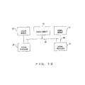
FIGS. 12 and 13 show examples of the configuration
of such a multiprocessor system. However, the secure
drive/medium 25 is omitted in these examples. In FIG.
12, the secure processor 24 and the normal processor
22 are connected to secure memory 91 through the same
system bus 92 (data bus, address bus) . In this case,
the secure memory 91 has the functions of the secure
memory 23 and the normal memory 21.
In FIG. 13, the secure processor 24 is connected
to the secure memory 23 through a system bus 94, and
connected to a shared memory 93 through a system bus
95. The normal processor 22 is connected to the normal
memory 21 through a system bus 96, but connected to the
shared memory 93 through the system bus 95. The shared
memory 93 is shared between the secure processor 24 and
the normal processor 22, and has the functions of the
secure memory 23 or/and the normal memory 21.
Since the configuration shown in FIG. 12 includes
one system bus and one memory unit, it is less costly
than the configuration shown in FIG. 13. However, since
the secure processor 24 and the normal processor 22 can
access the secure memory 91, the configuration shown
in FIG. 12 has a lower security level than the
configuration shown in FIG. 13. On the other hand, the
cost of the configuration shown in FIG. 13 exceeds
that shown in FIG. 12, but the security level of
the configuration shown in FIG. 13 is higher than that
shown in FIG. 12.
According to the above mentioned embodiments, the
secure processor 24 fetches and executes the code, but
a logical circuit for fetching, decrypting, and
executing an encrypted instruction can be automatically
generated using all or a part of the code. In this case,
a device for fixing a general purpose logical circuit
in a specific circuit state can be provided in the
system.
After verifying that the secure memory 23 is a
valid code, the secure processor 24 fixes all or a part
of the logical circuit in a circuit state in a
nonvolatile manner using the code. At this time, the
precedent circuit state is deleted, and newly
overwritten.
FIG. 14 is a flowchart of the circuit generating
process. The
secure processor 24 first fetches and
decrypts an encrypted instruction (step S41), and
translates the code into arithmetic operation circuit
configuration information (step S42). Next, the
circuit configuration information is translated into
wiring information (step S43), thereby fixing the wiring
information in a volatile manner (step S44). There can
be the following two methods for fixing wiring
information.
Thus, the process speed can be increased by
preparing processing portions by hardware.
Furthermore, when hardware and software processes are
used in combination, encrypted instructions can be
designed in a hierarchical structure to improve the
security level. For example, an instruction for a
specifically important portion can be realized as
hardware through a strict authenticating step, and other
instructions are processed by software in a simple
authenticating process for convenience of a user.
In the above mentioned embodiments, it is checked
using a signature whether or not a code is valid. As
the information for verification of the validity of a
code (verifying information), other arbitrary
information can be used. For example, a parity code,
a CRC (cyclic redundancy check) bit, etc. are added to
check whether or not a code is destroyed. Hereinafter,
a signature can be replaced with verifying information,
and the organization for adding the information to a
code is referred to as a code authentication
organization.
Next, a method for distributing a code provided
with verifying information is described below by
referring to FIGS. 17 through 22.
FIG. 17 shows a method for distributing a code to
a user. In FIG. 17, a code generator 101 provides a code
authentication organization 102 with a code (P1). The
code authentication organization 102 adds verifying
information after confirming the validity of the
received code, and provides an authenticated code for
a code user 103 (P2). The code user 103 has, for example,
the above mentioned multiprocessor system, confirms the
validity of the code according to the verifying
information added to the received code, and then uses
the code.
At this time, the code authentication
organization 102 presents the fee to the code generator
101, collects a code, and pays the fee when the code
is collected. Then, the code authentication
organization 102 presents a code fee to the code user
103, adds the verifying information, provides the code
for the code user 103, and simultaneously collects the
fee.
FIG. 18 shows such payment of fees. In FIG. 18,
the code generator 101 provides a code for the code
authentication organization 102 (P11), receives the fee
from the code authentication organization 102 (P12).
The code authentication organization 102 provides an
authenticated code for the code user 103 (P13), and the
code user 103 pays the fee to the code authentication
organization 102 (P14).
The fees paid by the code user 103 and the code
authentication organization 102 can be charged when the
code is provided, or depending on the code use/provision
state. In the latter case, for example, the fees are
charged depending on an amount of the code received by
the code user 103.
It is also possible that the code generator 101
pays a commission to the code authentication
organization 102 to add the verifying information to
a code and receives the fee paid by the code user 103.
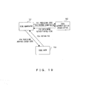
FIG. 19 shows such a method for distributing a code.
In FIG. 19, the code generator 101 provides a code for
the code authentication organization 102 (P21), pays
a commission required to add the verifying information
(P22), and obtains an authenticated code (P23). Then,
the code generator 101 provides the authenticated code
for the code user 103 (P24), and receives the fee (P25).
The fee paid by the code user 103 can be charged
at a time when a code is provided, or can be individually
charged depending on the code use/provision state.
Similarly, the commission paid by the code generator
101 can be charged collectively or individually.
Instead of the code generator 101, the code
authentication organization 102 can distribute a code.
In this case, the code authentication organization 102
provides an authenticated code for the code user 103
and collects the fee, and pays the collected fee to the
code generator 101.
In the code distributing method shown in FIG. 17,
it is possible that the
code authentication organization
102 divides the received code into two or more divisions,
first distributes a part of the divisions, and then
distributes the rest of the divisions at a request of
the
code user 103. In this case, the first distribution
is performed in any of the following methods.
FIG. 20 shows such a code distributing method. In
FIG. 20, the code generator 101 provides a code for the
code authentication organization 102 (P31). The code
authentication organization 102 confirms the validity
of the code, adds verifying information to the code,
and provides a part of the authenticated code for the
code user 103 (P32). The code user 103 first confirms
the validity of the part of the presented code according
to the verifying information, and then uses the code.
Furthermore, if necessary, The code user 103 obtains
the rest of the authenticated code from the code
authentication organization 102 and uses it (P33).
The code first provided is, for example, new year
card generating software limited in printing function,
game software recording only the first screen data, etc.
The rest of the code is, for example, new year card
generating software with all function restrictions
removed, game software recording the second and
subsequent screens, etc.
At this time, the code authentication
organization 102 presents a fee to the code generator
101, collects the code, and pays the fee for the
collection. Then, the code authentication
organization 102 presents a code fee for the remaining
part of the code to the code user 103, adds verifying
information, provides the code, and simultaneously
collects the fee.
FIG. 21 shows such payment of fees. In FIG. 21,
the processes of P41 and P42 are similar to the processes
of P11 and P12 shown in FIG. 18. Then, the code
authentication organization 102 distributes a part of
the authenticated code free of charge through, for
example, the CD-ROM (compact disk read only memory) as
an attachment to a magazine, Internet, etc. (P43). If
the code user 103 who has obtained and used it further
requests to use the rest of the code, then the user pays
the fee to the code authentication organization 102
(P45), and receives the rest of the code (P44).
As in FIG. 19, it is also possible to have a code
provided with verifying information by paying a
commission by the code generator 101 to the code
authentication organization 102. In this case, the
code generator 101 presents the fee for the rest of the
code to the code user 103, provides the code to the code
user 103, and simultaneously collects the fee.
FIG. 22 shows such a code distributing method. In
FIG. 22, the processes in P51, P52, and P53 are the same
as the processes in P21, P22, and P23 shown in FIG. 19.
The code generator 101 distributes free of charge a part
of an authenticated code, for example, in the above
mentioned method (P54). When the code user 103, who has
obtained and used the part of the code, requests to use
the rest of the code, the user pays the fee (P56), and
obtains the rest of the code (P55).
Instead of the code generator 101, the code
authentication organization 102 can distribute the code.
In this case, the code authentication organization 102
can present the fee for the rest of the code to the code
user 103, provides code for the code user 103 and
simultaneously collects the fee, and pays the collected
fee to the code generator 101.
According to the above mentioned code
distributing methods, since a code authenticated by a
code authentication organization is distributed, the
user can safely use the code. Thus, the number of code
users increases, and the codes can be widely
distributed.
The secure OS 51 shown in FIG. 5 is, for example,
stored in the secure drive/medium 25 in advance, and
loaded into the memory as necessary to start the
operation. It is also possible to externally store the
secure OS 51, and then install it in the system as
necessary.
FIG. 23 shows computer-readable storage media
capable of providing a multiprocessor system with a
program including the secure OS 51 and data.
The program and data stored in a database 112 of
a server 111 and a portable storage medium 113 are loaded
into memory 114 of the multiprocessor system. At this
time, the server 111 generates a propagation signal for
propagating the program and data, and transmits the
signal to the multiprocessor system through any
transmission medium in the network. Then, the
multiprocessor system executes the program using the
data, and performs a necessary process.
The portable storage medium 113 can be any
computer-readable storage medium such as a memory card,
a floppy disk, CD-ROM, an optical disk, a
magneto-optical disk, etc. The memory 114 corresponds
to the normal memory 21 or the secure memory 23 shown
in FIG. 2, the secure memory 91 shown in FIG. 12, or
the shared memory 93 shown in FIG. 13.
According to the present invention, a
heterogeneous multiprocessor system can be configured
including a secure processor with a secure task and an
unsecured task separately allocated, thereby realizing
an easy control process by the OS, and efficiently
performing a secure process. Furthermore, a code can
be efficiently performed by attaching a signature for
each part of a code read into a memory when the signature
is attached to a code of a secure task.