EP1278081A2 - Variable wavelength dispersion compensator - Google Patents
Variable wavelength dispersion compensator Download PDFInfo
- Publication number
- EP1278081A2 EP1278081A2 EP01126565A EP01126565A EP1278081A2 EP 1278081 A2 EP1278081 A2 EP 1278081A2 EP 01126565 A EP01126565 A EP 01126565A EP 01126565 A EP01126565 A EP 01126565A EP 1278081 A2 EP1278081 A2 EP 1278081A2
- Authority
- EP
- European Patent Office
- Prior art keywords
- mirror
- dispersion
- beams
- shape
- wavelength dispersion
- Prior art date
- Legal status (The legal status is an assumption and is not a legal conclusion. Google has not performed a legal analysis and makes no representation as to the accuracy of the status listed.)
- Ceased
Links
Images






Classifications
-
- G—PHYSICS
- G02—OPTICS
- G02B—OPTICAL ELEMENTS, SYSTEMS OR APPARATUS
- G02B6/00—Light guides; Structural details of arrangements comprising light guides and other optical elements, e.g. couplings
- G02B6/24—Coupling light guides
- G02B6/26—Optical coupling means
- G02B6/35—Optical coupling means having switching means
- G02B6/351—Optical coupling means having switching means involving stationary waveguides with moving interposed optical elements
- G02B6/3512—Optical coupling means having switching means involving stationary waveguides with moving interposed optical elements the optical element being reflective, e.g. mirror
- G02B6/352—Optical coupling means having switching means involving stationary waveguides with moving interposed optical elements the optical element being reflective, e.g. mirror the reflective optical element having a shaped reflective surface, e.g. a reflective element comprising several reflective surfaces or facets that function together
-
- G—PHYSICS
- G02—OPTICS
- G02B—OPTICAL ELEMENTS, SYSTEMS OR APPARATUS
- G02B6/00—Light guides; Structural details of arrangements comprising light guides and other optical elements, e.g. couplings
- G02B6/24—Coupling light guides
- G02B6/26—Optical coupling means
- G02B6/28—Optical coupling means having data bus means, i.e. plural waveguides interconnected and providing an inherently bidirectional system by mixing and splitting signals
- G02B6/293—Optical coupling means having data bus means, i.e. plural waveguides interconnected and providing an inherently bidirectional system by mixing and splitting signals with wavelength selective means
- G02B6/29346—Optical coupling means having data bus means, i.e. plural waveguides interconnected and providing an inherently bidirectional system by mixing and splitting signals with wavelength selective means operating by wave or beam interference
- G02B6/29358—Multiple beam interferometer external to a light guide, e.g. Fabry-Pérot, etalon, VIPA plate, OTDL plate, continuous interferometer, parallel plate resonator
-
- G—PHYSICS
- G02—OPTICS
- G02B—OPTICAL ELEMENTS, SYSTEMS OR APPARATUS
- G02B6/00—Light guides; Structural details of arrangements comprising light guides and other optical elements, e.g. couplings
- G02B6/24—Coupling light guides
- G02B6/26—Optical coupling means
- G02B6/28—Optical coupling means having data bus means, i.e. plural waveguides interconnected and providing an inherently bidirectional system by mixing and splitting signals
- G02B6/293—Optical coupling means having data bus means, i.e. plural waveguides interconnected and providing an inherently bidirectional system by mixing and splitting signals with wavelength selective means
- G02B6/29379—Optical coupling means having data bus means, i.e. plural waveguides interconnected and providing an inherently bidirectional system by mixing and splitting signals with wavelength selective means characterised by the function or use of the complete device
- G02B6/29392—Controlling dispersion
- G02B6/29394—Compensating wavelength dispersion
-
- G—PHYSICS
- G02—OPTICS
- G02B—OPTICAL ELEMENTS, SYSTEMS OR APPARATUS
- G02B6/00—Light guides; Structural details of arrangements comprising light guides and other optical elements, e.g. couplings
- G02B6/24—Coupling light guides
- G02B6/26—Optical coupling means
- G02B6/28—Optical coupling means having data bus means, i.e. plural waveguides interconnected and providing an inherently bidirectional system by mixing and splitting signals
- G02B6/293—Optical coupling means having data bus means, i.e. plural waveguides interconnected and providing an inherently bidirectional system by mixing and splitting signals with wavelength selective means
- G02B6/29379—Optical coupling means having data bus means, i.e. plural waveguides interconnected and providing an inherently bidirectional system by mixing and splitting signals with wavelength selective means characterised by the function or use of the complete device
- G02B6/29395—Optical coupling means having data bus means, i.e. plural waveguides interconnected and providing an inherently bidirectional system by mixing and splitting signals with wavelength selective means characterised by the function or use of the complete device configurable, e.g. tunable or reconfigurable
-
- G—PHYSICS
- G02—OPTICS
- G02B—OPTICAL ELEMENTS, SYSTEMS OR APPARATUS
- G02B6/00—Light guides; Structural details of arrangements comprising light guides and other optical elements, e.g. couplings
- G02B6/24—Coupling light guides
- G02B6/26—Optical coupling means
- G02B6/32—Optical coupling means having lens focusing means positioned between opposed fibre ends
-
- G—PHYSICS
- G02—OPTICS
- G02B—OPTICAL ELEMENTS, SYSTEMS OR APPARATUS
- G02B6/00—Light guides; Structural details of arrangements comprising light guides and other optical elements, e.g. couplings
- G02B6/24—Coupling light guides
- G02B6/26—Optical coupling means
- G02B6/35—Optical coupling means having switching means
- G02B6/3564—Mechanical details of the actuation mechanism associated with the moving element or mounting mechanism details
- G02B6/3568—Mechanical details of the actuation mechanism associated with the moving element or mounting mechanism details characterised by the actuating force
- G02B6/3578—Piezoelectric force
Definitions
- the present invention relates to a variable wavelength dispersion compensator for variably compensating wavelength dispersion in an optical fiber communications system.
- An optical fiber communications system generally has a problem that the distortion of a transmission waveform due to optical fiber wavelength dispersion (chromatic dispersion) degrades signal quality. Therefore, the wavelength dispersion must be compensated.
- variable dispersion compensators For a dispersion compensation method, a method for restoring waveform distortion by inserting a device having a dispersion characteristic the opposite of an optical fiber (dispersion compensation fiber) in a transmission line is used. Furthermore, variable dispersion compensators have been developed which incorporate a chromatic dispersion generation device (VIPA) and a light-returning device (non-spherical mirror) in order to cope with the change of the dispersion characteristic due to the temperature, the pressure and the like of an optical fiber (Japanese Patent Applications 10-534450 and 11-513133).
- VIPA chromatic dispersion generation device
- non-spherical mirror non-spherical mirror
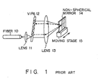
- Fig. 1 shows the basic configuration of a variable dispersion compensator using a VIPA.
- Beams inputted from a fiber 10 are collected in a form of a line or dots by a lens 11 and are inputted to a VIPA 12.
- the VIPA is a transparent parallel plate on both sides of which a reflection film is formed. Although one reflection film has a reflectance of 100%, the other has a reflectance of less than 100%, and typically of 95%. Therefore, beams inputted to the VIPA 12 are repeatedly reflected between these reflection films and some of the beams are repeatedly outputted to the outside at one time from a surface with a low reflectance. Since the beams are outputted to the outside at each reflection, the beams have phase differences between each other. Therefore, if the beams interfere with each other, beams with a prescribed wavelength are formed into luminous flux that propagates in a prescribed direction.
- the VIPA 12 is a device for generating a plurality of pieces of luminous flux that propagates in different directions depending on the wavelengths.
- the outputted beams are collected at a lens 13 and are reflected on a non-spherical mirror 14.
- the distance between the lens 11 and fiber 10 that the beam propagates can be changed. Specifically, the propagation distance can be extended, and propagation delay can be applied to the beam. If a plurality of beams with different wavelengths take different routes, the respective propagation delay of the beams can be changed by a wavelength, and wavelength dispersion can be generated, accordingly. If the wavelength dispersion of an optical fiber is compensated, a reciprocal dispersion having a reverse characteristic of canceling the wavelength dispersion of the beam is applied to the beam.
- This compensator has a characteristic of freely changing a compensation amount by moving the non-spherical mirror depending on a dispersion value.
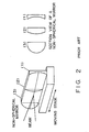
- the non-spherical mirror has a gradation structure, such as a concave surface and a convex surface.
- Fig. 2 shows a non-spherical mirror.
- This non-spherical mirror is located on a moving stage. If the mirror is moved in the direction of an arrow shown in Fig. 2, the shape of the light input position of the mirror changes. Therefore, a plurality of different chromatic dispersions (wavelength dispersions) can be generated.
- Fig. 3 shows the wavelength dispersion and signal degradation of a transmission line, and the compensation.
- a variable dispersion compensator hereinafter a VIPA, for example
- the distortion of the pulse can be compensated. Therefore, the receiver can receive a pulse without distortion (3).
- Fig. 4 shows dispersion to be compensated by a VIPA.
- dispersion compensation by a VIPA means the total dispersion amount is reduced to 0ps/nm.
- a post-compensation pulse of 0ps/nm is generated.
- the VIPA reduces the total dispersion amount to zero by shifting the dispersion amount that a beam suffers from the propagation through the optical fiber upward or downward (reciprocal dispersion).
- the stage must be moved depending on a dispersion compensation amount. Therefore, if the compensation range is extended, the non-spherical mirror must be made longer and a movement amount also increases. However, since the increase in a stage movement amount greatly affects the accuracy of the stage movement, dispersion cannot be accurately compensated, which is a problem.
- the mirror can compensate for only a specific band. Therefore, in order to compensate for a new band, a new non-spherical mirror must be designed.
- Fig. 5 shows a case where the conventional wavelength dispersion method is applied to a WDM beam.
- ⁇ 1, ⁇ 0, and ⁇ 2 take different dispersion values depending on the wavelengths, that is, a dispersion slope in an optical fiber (curve 1).
- the dispersion is shifted so that the dispersion value of ⁇ 0 becomes zero in a VIPA, as shown in Fig. 4, the dispersion values of ⁇ 1 and ⁇ 2 do not become zero. Since the VIPA shifts the curve by a specific dispersion amount throughout the entire wavelength, the VIPA simply shifts curve 1 upward or downward. Therefore, it is impossible to simultaneously reduce all the dispersion values of ⁇ 1, ⁇ 0 and ⁇ 2 to zero, which is also a problem.
- variable wavelength dispersion compensator of the present invention comprises an angular dispersion unit giving angular dispersion to an input beam and a surface-shape variable mirror returning the angle-dispersed beam to the angular dispersion unit, the surface shape of which can be changed.
- the compensator gives desired wavelength dispersion to a beam by reflecting a beam inputted from the angular dispersion unit on the surface-shape variable mirror unit, inputting the reflected beam to the angular dispersion unit again, and outputting the beam from the angular dispersion unit.
- the mirror shape can be changed for each wavelength, wavelength dispersion can be appropriately compensated and a wavelength dispersion slope can also be appropriately compensated.
- variable wavelength dispersion compensator of the present invention can cope with a change in the wavelength dispersion characteristic of an optical fiber due to deterioration caused by aging, a change in a wavelength dispersion amount to be compensated due to the extension of a transmission line and the like, by changing the surface shape of the mirror of the compensator without replacing the compensator itself.
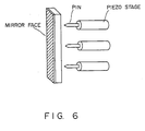
- Fig. 6 shows the basic configuration of the preferred embodiment of the present invention.
- a wavelength dispersion compensator using a VIPA uses a mirror, the surface shape of which can be changed, as a non-spherical mirror.
- the surface-shape variable mirror shown in Fig. 6 comprises a thin mirror, piezo stages and pins.
- the pin is attached to the tip of the piezo stage, and this pin and the mirror face are joined.
- Figs. 7A and 7B show the operation of the surface-shape variable mirror of this preferred embodiment.
- a concave mirror face can be formed. This corresponds to the section (1) of the non-spherical mirror shown in Fig. 2. If the upper and lower stages are squeezed and the middle stage is expanded, the section shown in Fig. 7B is obtained. This corresponds to the section (3) shown in Fig. 2.
- the surface-shape variable mirror comprises one mirror and a plurality of piezo stages.
- the plurality of piezo stages By expanding/squeezing the plurality of piezo stages, a variety of mirror shapes can be formed. Therefore, there is no need to prepare all necessary shapes in advance, unlike a non-spherical mirror, and only one mirror can produce any desired shape.
- the piezo stage can be controlled in units of several nanometers, a fine surface shape can be produced.
- the mirror can be produced by evaporating gold onto a thin glass plate yielding a thickness of approximately 100 ⁇ m. Basically, it is sufficient if both the glass plate and the evaporated gold have sufficient thickness to not break when the piezo stage is expanded/squeezed and if the surface is a mirror.
- Problem No. 1 can be solved by using the surface-shape variable mirror described above. Specifically, even if a compensation band is expanded, it is sufficient to change a mirror shape by appropriately collecting beams on a lens and changing the movement amount of the piezo stage. Therefore, there is no problem of accuracy degradation accompanying both an increase of mirror length and an increase of a stage movement amount. Even if a compensation range is modified, there is no need to prepare a new mirror and the problem can be easily solved by transforming a mirror surface shape.
- Problem No. 2 can be solved as follows. By separating WDM beams for each wavelength using a diffraction grid and the like, applying this mirror for each wavelength and optimally compensating for dispersion for each wavelength, the dispersion of each wavelength can be reduced to zero.
- Fig. 8 shows the configuration of the first preferred embodiment of the present invention.
- the first preferred embodiment can be implemented by replacing the non-spherical mirror and moving stage with a surface-shape variable mirror.
- Beams inputted from a fiber 10 are collected at a VIPA 12 by a lens 11 and are outputted as a plurality of pieces of different flux for each wavelength.
- the outputted beams are collected at a surface-shape variable mirror 20 by a lens 13.
- a piezo stage 21 is provided at the back of the surface-shape variable mirror 20, and the mirror face of the surface-shape variable mirror 20 can be transformed into an arbitrary shape.
- Prescribed wavelength dispersion can be generated by calculating wavelength dispersion to be generated by the VIPA 12 and determining the shape of the mirror face so as to generate desired dispersion.
- Fig. 9 shows the configuration of the second preferred embodiment.
- the output beams from the VIPA 12 are branched for each wavelength using a diffraction grid, and the branched beams are collected at a plurality of surface-shape variable mirrors (variable mirrors 1-3). Beams can be branched into, for example, three groups of ⁇ 1, ⁇ 0, and ⁇ 2 ( ⁇ 1 ⁇ 0 ⁇ 2) shown in Fig. 9 for each wavelength by using a diffraction grid.
- a diffraction grid 25 is used to branch beams for each wavelength, anything that causes the dispersion of a wavelength, such as a prism, can be used.
- Each group of beams with a different wavelength is collected at a different point through a lens.
- ⁇ 1, ⁇ 0, and ⁇ 2 are collected at a surface-shape variable mirror 1 (variable mirror 1), a surface-shape variable mirror 2 (variable mirror 2), and a surface-shape variable mirror 3 (variable mirror 3), respectively.
- the surface-shape variable mirrors 1-3 (variable mirrors 1-3) can produce different surface shapes. Therefore, a different dispersion value can be given to each of ⁇ 1, ⁇ 0, and ⁇ 2.
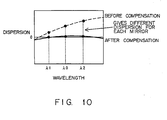
- Fig. 10 shows the effects of the configuration shown in Fig. 9. Specifically, as shown in Fig. 10, if a different dispersion is given for each wavelength using the surface-shape variable mirror of this preferred embodiment when dispersion before compensation is as shown by the broken line, after compensation, all dispersion values can be reduced to zero, as shown by the solid line. Therefore, the dispersion slope of a WDM beam can also be compensated.
- a plurality of surface-shape variable mirrors are located separately and in parallel, there is no need to separate the plurality of mirrors.
- a piezo stage can also be two-dimensionally located against one large mirror.
- Figs . 11 and 12 show the detailed structure of such a variable mirror.
- a glass plate (silica system glass) having both the thickness of 100 ⁇ m and the outer dimensions of 10 ⁇ 3mm is used.
- Figs. 11 and 12 show the longer side section of the glass plate.
- a glass plate having some hardness, the elasticity of which can be changed, and which cannot be broken is used.
- Each end of the mirror is mechanically fixed. This joint and the piezo are fixed by soldering and the like. The pin and the back of the mirror are also fixed by soldering and the like. It is assumed that the mirror is used in a state where there is a small displacement amount and there is no plasticity transformation in the solder layer, and in realty the mirror is used in a state where the solder will not be broken off.
- the mirror is designed so that both the pin and solder can be easily seen.
- the middle piezo stage is located in such a way that the distance between the variable mirror and middle piezo stage becomes the same as both the distance between the variable mirror and upper piezo stage and the distance between the variable mirror and lower piezo stage.
- one middle piezo stage is provided, in reality, two or more middle piezo stages can also be provided. By providing many piezo stages, a mirror face with a more complex shape can be produced.
- the thickness of the plating is thin enough to be sufficient for the elasticity to change as the glass plate is transformed and is thick enough to be sufficient for the plating to be prevented from tearing off as the elasticity of the glass plate changes.
- the supporting table of the piezo stages which is not shown in Fig. 11, is not especially limited if the piezo stages can be properly fixed at a prescribed position.
- the piezo stage has one shaft.
- the piezo stage moves in the vertical direction against the mirror face (horizontal direction against a paper surface).
- the pin of the middle piezo stage is expanded, as shown in Fig. 12, a convex mirror face can be formed.
- a concave mirror face is formed.
- a wavy mirror face can also be formed. In this way, by providing two or more piezo stages, a more complex mirror face can be formed.
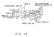
- Fig. 13 shows the configuration of the third preferred embodiment of the present invention.
- a plurality of separate variable mirrors are provided to compensate for wavelength dispersion with a plurality of wavelengths and to eliminate the influence of a dispersion slope from beams.
- a two-dimensional variable mirror 30 obtained by incorporating these mirrors is used instead of the plurality of separate variable mirrors.
- Beams inputted to a fiber 10 are branched for each wavelength by a diffraction grid 25 after passing through both a lens 11 and a VIPA 12 and after being angular-dispersed.
- the beams are branched into three groups of beams with wavelengths ⁇ 1, ⁇ 0 and ⁇ 2.
- piezo stages 31 are two-dimensionally located and a mirror face 32 can be transformed more complexly.
- the mirror face 32 are continuously transformed up to a position where beams with wavelength ⁇ 0 hit the mirror face and the position where beams with wavelength ⁇ 0 hit the mirror face has a shape suited for appropriately compensating for the dispersion of beams with wavelength ⁇ 0.
- the mirror face 32 are continuously transformed up to a position where beams with wavelength ⁇ 2 hit the mirror face and the position where beams with wavelength ⁇ 2 hit the mirror face has a shape suited for appropriately compensating for the dispersion of beams with wavelength ⁇ 2.
- the number of piezo stages 31 is increased and a more complex mirror face can thus be formed. Then, one mirror face can compensate for a plurality of beam groups with a plurality of wavelengths.
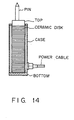
- Fig. 14 shows the structure of a piezo stage.
- the piezo stage comprises a piezo stack having a pin at the tip.
- the piezo stack is cased.
- the piezo stack has a structure where a plurality of ceramic disks are piled sandwiching electrodes. If a voltage is applied to the electrode, the ceramic disks expand/contract. Then, the expansion/contraction of the ceramic disks moves the pin attached at the tip of the piezo stack.
- a power cable is connected to the case that encloses a piezo stack, and voltage can be applied to the electrode, accordingly.
- a VIPA is described as one example of a device for angular-dispersing inputted beams, according to the present invention, the device is not limited to a VIPA.
- the combination of a transmission type diffraction grid and a reflection type diffraction grid can also be used to perform a function equivalent to a VIPA.
- the surface-shape variable mirror is not limited to the combination of a glass plate and piezo stages, which a person having an ordinary skill in the art can easily understand.
- dispersion slope compensation can also be implemented, which was impossible by the conventional method.
Landscapes
- Physics & Mathematics (AREA)
- General Physics & Mathematics (AREA)
- Optics & Photonics (AREA)
- Chemical & Material Sciences (AREA)
- Dispersion Chemistry (AREA)
- Mechanical Light Control Or Optical Switches (AREA)
- Optical Communication System (AREA)
Abstract
Description
Claims (7)
- A variable wavelength dispersion compensator, comprising:an angular dispersion means (12) for giving angular dispersion to a plurality of the wavelengths of input beams; anda surface-shape variable mirror means (20) for returning the angle-dispersed beams to the angular dispersion means (12), a surface shape of which can be transformed, wherein wavelength dispersion is given to the beams by reflecting the beams from the angular dispersion unit on the surface-shape variable mirror unit, inputting the reflected beams to the angular dispersion means (12) again and outputting the inputted beams from the angular dispersion means (12).
- The variable wavelength dispersion compensator according to claim 1, wherein said surface-shape variable mirror means (20) further comprises:a mirror face means (20) for reflecting beams; anda plurality of stage means (21) for setting a mirror face to a desired shape, which contacts a back surface of the mirror means (20).
- The variable wavelength dispersion compensator according to claim 2, wherein said mirror means (20) is a thin plate, the elasticity of which can be changed.
- The variable wavelength dispersion compensator according to claim 1, further comprising
a branching means (25) for branching the angular-dispersed beams into a plurality of beam groups with a plurality of different wavelengths, wherein the plurality of said surface-shape variable mirror means (20) are provided and each surface shape is set so that wavelength dispersion can be compensated for each branched beam group. - The variable wavelength dispersion compensator according to claim 4, wherein the plurality of said surface-shape variable mirror means (20) are incorporated into one surface-shape variable mirror means (20), which has a surface transformed in a two-dimensional direction so that each branched beam group can be received on a part of the surface and prescribed wavelength dispersion is given to the branched beam group.
- The variable wavelength dispersion compensator according to claim 4, wherein said branching means (25) is a diffraction grid.
- The variable wavelength dispersion compensator according to claim 4, wherein said branching means (25) is a VIPA.
Applications Claiming Priority (2)
| Application Number | Priority Date | Filing Date | Title |
|---|---|---|---|
| JP2001216415A JP2003029168A (en) | 2001-07-17 | 2001-07-17 | Variable wavelength dispersion compensator |
| JP2001216415 | 2001-07-17 |
Publications (2)
| Publication Number | Publication Date |
|---|---|
| EP1278081A2 true EP1278081A2 (en) | 2003-01-22 |
| EP1278081A3 EP1278081A3 (en) | 2004-04-07 |
Family
ID=19050896
Family Applications (1)
| Application Number | Title | Priority Date | Filing Date |
|---|---|---|---|
| EP01126565A Ceased EP1278081A3 (en) | 2001-07-17 | 2001-11-15 | Variable wavelength dispersion compensator |
Country Status (3)
| Country | Link |
|---|---|
| US (2) | US6832020B2 (en) |
| EP (1) | EP1278081A3 (en) |
| JP (1) | JP2003029168A (en) |
Cited By (3)
| Publication number | Priority date | Publication date | Assignee | Title |
|---|---|---|---|---|
| EP1659387A1 (en) * | 2004-11-23 | 2006-05-24 | Acterna Germany GmbH | Device for and method of measuring the chromatic dispersion |
| WO2009086699A1 (en) * | 2008-01-08 | 2009-07-16 | Lucent Technologies Inc. | Eye piece and tunable chromatic dispersion compensator using the same |
| EP3239647A3 (en) * | 2016-04-28 | 2018-01-17 | Kiwamu Takehisa | Laser defense system and high altitude airship |
Families Citing this family (11)
| Publication number | Priority date | Publication date | Assignee | Title |
|---|---|---|---|---|
| JP3973021B2 (en) * | 2002-03-29 | 2007-09-05 | 富士通株式会社 | Equipment using a virtual imaged phased array (VIPA) with improved transmission wavelength characteristics of output light |
| JP4152836B2 (en) * | 2003-08-22 | 2008-09-17 | 富士通株式会社 | Optical component with wavelength division function and wavelength dispersion compensator |
| JP4518825B2 (en) | 2004-03-31 | 2010-08-04 | 富士通株式会社 | Variable wavelength dispersion compensator |
| JP4513471B2 (en) * | 2004-09-14 | 2010-07-28 | 沖電気工業株式会社 | Demultiplexer |
| JP4439411B2 (en) * | 2005-02-18 | 2010-03-24 | 富士通株式会社 | Optical transmission system |
| JP4545023B2 (en) * | 2005-03-14 | 2010-09-15 | 富士通株式会社 | Chromatic dispersion and dispersion slope compensator |
| JP4470801B2 (en) * | 2005-04-19 | 2010-06-02 | 船井電機株式会社 | Variable shape mirror and optical pickup device having the same |
| WO2008064470A1 (en) * | 2006-11-27 | 2008-06-05 | Roctest Ltée | High selectivity band-pass interferometer with tuning capabilities |
| US7504609B2 (en) * | 2007-02-07 | 2009-03-17 | Raytheon Company | Phased-array light telescope |
| JP5312409B2 (en) * | 2010-07-08 | 2013-10-09 | 三菱電機株式会社 | Deformable mirror |
| IT201700114962A1 (en) * | 2017-10-12 | 2019-04-12 | Automotive Lighting Italia Spa | SIMULTANEOUS LASER WELDING EQUIPMENT FOR A AUTOMOTIVE HEADLAMP AND SIMULTANEOUS LASER WELDING METHOD OF A AUTOMOTIVE HEADLAMP |
Family Cites Families (15)
| Publication number | Priority date | Publication date | Assignee | Title |
|---|---|---|---|---|
| DE3731075A1 (en) * | 1987-09-16 | 1989-03-30 | Bosch Gmbh Robert | BRAKE SLIP CONTROL |
| US5166818A (en) | 1991-03-11 | 1992-11-24 | Bell Communications Research, Inc. | Optical pulse-shaping device and method, and optical communications station and method |
| JPH05136509A (en) | 1991-11-11 | 1993-06-01 | Hitachi Ltd | Laser light output device, laser light wavefront control method and device thereof |
| JP3070892B2 (en) * | 1993-08-24 | 2000-07-31 | 株式会社日立製作所 | Variable shape mirror, adaptive optics device, astronomical telescope, laser isotope separation device, and laser processing machine |
| JPH08193805A (en) | 1995-01-13 | 1996-07-30 | Fuji Xerox Co Ltd | Optical interferometer and interference measuring method using the same |
| US5969865A (en) | 1995-07-26 | 1999-10-19 | Fujitsu Limited | Optical apparatus which uses a virtually imaged phased array to produce chromatic dispersion |
| US5930045A (en) * | 1995-07-26 | 1999-07-27 | Fujitsu, Ltd. | Optical apparatus which uses a virtually imaged phased array to produce chromatic dispersion |
| US6028706A (en) * | 1995-07-26 | 2000-02-22 | Fujitsu Limited | Virtually imaged phased array (VIPA) having a varying reflectivity surface to improve beam profile |
| JPH10188319A (en) | 1996-12-26 | 1998-07-21 | Sharp Corp | Deformable mirror and optical recording / reproducing apparatus using the deformable mirror |
| US6298080B1 (en) * | 1999-03-12 | 2001-10-02 | Lambda Physik Ag | Narrow band excimer or molecular fluorine laser with adjustable bandwidth |
| JP2000298237A (en) * | 1999-04-13 | 2000-10-24 | Olympus Optical Co Ltd | Eccentric optical system |
| US6263127B1 (en) * | 1999-05-13 | 2001-07-17 | Lucent Technologies Inc. | Free-space/arrayed-waveguide router |
| US6343866B1 (en) * | 2000-05-23 | 2002-02-05 | Fujitsu Limited | Optical apparatus which uses a virtually imaged phased array to produce chromatic dispersion |
| US6556320B1 (en) * | 2000-05-19 | 2003-04-29 | Avanex Corporation | Tunable chromatic dispersion, dispersion slope, and polarization mode dispersion compensator utilizing a virtually imaged phased array |
| JP2003015076A (en) * | 2001-07-04 | 2003-01-15 | Fujitsu Ltd | Chromatic dispersion compensator that can compensate up to higher order dispersion |
-
2001
- 2001-07-17 JP JP2001216415A patent/JP2003029168A/en active Pending
- 2001-11-08 US US09/986,293 patent/US6832020B2/en not_active Expired - Fee Related
- 2001-11-15 EP EP01126565A patent/EP1278081A3/en not_active Ceased
-
2004
- 2004-09-27 US US10/949,378 patent/US7197211B2/en not_active Expired - Fee Related
Cited By (4)
| Publication number | Priority date | Publication date | Assignee | Title |
|---|---|---|---|---|
| EP1659387A1 (en) * | 2004-11-23 | 2006-05-24 | Acterna Germany GmbH | Device for and method of measuring the chromatic dispersion |
| WO2009086699A1 (en) * | 2008-01-08 | 2009-07-16 | Lucent Technologies Inc. | Eye piece and tunable chromatic dispersion compensator using the same |
| US8238031B2 (en) | 2008-01-08 | 2012-08-07 | Alcatel Lucent | Eye piece and tunable chromatic dispersion compensator using the same |
| EP3239647A3 (en) * | 2016-04-28 | 2018-01-17 | Kiwamu Takehisa | Laser defense system and high altitude airship |
Also Published As
| Publication number | Publication date |
|---|---|
| US20030016908A1 (en) | 2003-01-23 |
| US6832020B2 (en) | 2004-12-14 |
| US20050041921A1 (en) | 2005-02-24 |
| US7197211B2 (en) | 2007-03-27 |
| EP1278081A3 (en) | 2004-04-07 |
| JP2003029168A (en) | 2003-01-29 |
Similar Documents
| Publication | Publication Date | Title |
|---|---|---|
| US6832020B2 (en) | Variable wavelength dispersion compensator | |
| US7397981B2 (en) | Apparatus and method of compensating for wavelength dispersion of optical transmission line | |
| EP1271211A2 (en) | Optical coupling device with optical waveguide coupled to optical device | |
| EP1554619B1 (en) | Compensating for chromatic dispersion in optical fibers | |
| US6493488B1 (en) | Apparatus and method for high speed optical signal processing | |
| JP4518825B2 (en) | Variable wavelength dispersion compensator | |
| US6775434B2 (en) | Variable optical dispersion compensator | |
| JP3994737B2 (en) | Optical device | |
| JP4479130B2 (en) | Variable dispersion compensator and optical transmission system | |
| US20030053174A1 (en) | Optical equalizing of chromatic and polarization mode dispersion | |
| US20040057115A1 (en) | Optical device | |
| US7184665B2 (en) | Tunable dispersion compensator | |
| JP2003294999A (en) | Apparatus using virtual imaged phased array (VIPA) with improved transmission wavelength characteristics of output light | |
| US20050249458A1 (en) | Wavelength selection device | |
| US20070014515A1 (en) | Variable dispersion compensator | |
| JP4604754B2 (en) | Variable dispersion compensator | |
| AU784643B2 (en) | Variable dispersion compensator and optical transmission system | |
| JP2000028849A (en) | Virtually imaged phased array (VIPA) with variable reflectivity to improve beam profile | |
| US20050025415A1 (en) | Movable mirror device, dispersion compensator, gain equalizer, and optical ADM apparatus | |
| KR20040040486A (en) | Temperature-compensation optical communication interference device and optical communication system | |
| JP2006323175A (en) | Optical output method and optical output device | |
| JP2003015076A (en) | Chromatic dispersion compensator that can compensate up to higher order dispersion | |
| JP2005292248A (en) | Optical device | |
| JP2007334225A (en) | Optical pulse width conversion device and optical pulse width conversion method | |
| CA2390768A1 (en) | Tunable dispersion compensator |
Legal Events
| Date | Code | Title | Description |
|---|---|---|---|
| PUAI | Public reference made under article 153(3) epc to a published international application that has entered the european phase |
Free format text: ORIGINAL CODE: 0009012 |
|
| AK | Designated contracting states |
Kind code of ref document: A2 Designated state(s): AT BE CH CY DE DK ES FI FR GB GR IE IT LI LU MC NL PT SE TR |
|
| AX | Request for extension of the european patent |
Free format text: AL;LT;LV;MK;RO;SI |
|
| PUAL | Search report despatched |
Free format text: ORIGINAL CODE: 0009013 |
|
| AK | Designated contracting states |
Kind code of ref document: A3 Designated state(s): AT BE CH CY DE DK ES FI FR GB GR IE IT LI LU MC NL PT SE TR |
|
| AX | Request for extension of the european patent |
Extension state: AL LT LV MK RO SI |
|
| RIC1 | Information provided on ipc code assigned before grant |
Ipc: 7G 02B 6/34 B Ipc: 7G 02B 6/293 A |
|
| 17P | Request for examination filed |
Effective date: 20040430 |
|
| 17Q | First examination report despatched |
Effective date: 20040601 |
|
| AKX | Designation fees paid |
Designated state(s): DE FR GB |
|
| STAA | Information on the status of an ep patent application or granted ep patent |
Free format text: STATUS: THE APPLICATION HAS BEEN REFUSED |
|
| 18R | Application refused |
Effective date: 20070629 |