EP1278072A1 - Device for judging life of auxiliary battery - Google Patents
Device for judging life of auxiliary battery Download PDFInfo
- Publication number
- EP1278072A1 EP1278072A1 EP00935592A EP00935592A EP1278072A1 EP 1278072 A1 EP1278072 A1 EP 1278072A1 EP 00935592 A EP00935592 A EP 00935592A EP 00935592 A EP00935592 A EP 00935592A EP 1278072 A1 EP1278072 A1 EP 1278072A1
- Authority
- EP
- European Patent Office
- Prior art keywords
- auxiliary battery
- discharge
- depth
- determining device
- life determining
- Prior art date
- Legal status (The legal status is an assumption and is not a legal conclusion. Google has not performed a legal analysis and makes no representation as to the accuracy of the status listed.)
- Granted
Links
Images

Classifications
-
- G—PHYSICS
- G01—MEASURING; TESTING
- G01R—MEASURING ELECTRIC VARIABLES; MEASURING MAGNETIC VARIABLES
- G01R31/00—Arrangements for testing electric properties; Arrangements for locating electric faults; Arrangements for electrical testing characterised by what is being tested not provided for elsewhere
- G01R31/36—Arrangements for testing, measuring or monitoring the electrical condition of accumulators or electric batteries, e.g. capacity or state of charge [SoC]
- G01R31/385—Arrangements for measuring battery or accumulator variables
- G01R31/386—Arrangements for measuring battery or accumulator variables using test-loads
-
- G—PHYSICS
- G01—MEASURING; TESTING
- G01R—MEASURING ELECTRIC VARIABLES; MEASURING MAGNETIC VARIABLES
- G01R31/00—Arrangements for testing electric properties; Arrangements for locating electric faults; Arrangements for electrical testing characterised by what is being tested not provided for elsewhere
- G01R31/36—Arrangements for testing, measuring or monitoring the electrical condition of accumulators or electric batteries, e.g. capacity or state of charge [SoC]
- G01R31/3644—Constructional arrangements
- G01R31/3647—Constructional arrangements for determining the ability of a battery to perform a critical function, e.g. cranking
-
- G—PHYSICS
- G01—MEASURING; TESTING
- G01R—MEASURING ELECTRIC VARIABLES; MEASURING MAGNETIC VARIABLES
- G01R31/00—Arrangements for testing electric properties; Arrangements for locating electric faults; Arrangements for electrical testing characterised by what is being tested not provided for elsewhere
- G01R31/36—Arrangements for testing, measuring or monitoring the electrical condition of accumulators or electric batteries, e.g. capacity or state of charge [SoC]
- G01R31/3644—Constructional arrangements
- G01R31/3648—Constructional arrangements comprising digital calculation means, e.g. for performing an algorithm
-
- G—PHYSICS
- G01—MEASURING; TESTING
- G01R—MEASURING ELECTRIC VARIABLES; MEASURING MAGNETIC VARIABLES
- G01R31/00—Arrangements for testing electric properties; Arrangements for locating electric faults; Arrangements for electrical testing characterised by what is being tested not provided for elsewhere
- G01R31/36—Arrangements for testing, measuring or monitoring the electrical condition of accumulators or electric batteries, e.g. capacity or state of charge [SoC]
- G01R31/378—Arrangements for testing, measuring or monitoring the electrical condition of accumulators or electric batteries, e.g. capacity or state of charge [SoC] specially adapted for the type of battery or accumulator
- G01R31/379—Arrangements for testing, measuring or monitoring the electrical condition of accumulators or electric batteries, e.g. capacity or state of charge [SoC] specially adapted for the type of battery or accumulator for lead-acid batteries
Definitions
- the present invention relates to an auxiliary battery life determining device that determines the life of an auxiliary battery for use in case of emergency.
- An emergency reporting system or the like may sometimes be loaded with an auxiliary battery, in addition to a main battery (a lead-acid battery) for normal operation, so as to exclude the possibility of the system becoming inoperative in emergencies.
- auxiliary battery a lead-acid battery
- auxiliary battery for emergency use is also exhausted by spontaneous discharge, and hence in some cases it cannot be used even if switched from the main battery in an emergency.
- Pat. Pub. Gazette-No. 10-153647 adopts a scheme that compares the output voltages from the secondary battery under no-load conditions and under load conditions, and uses the difference to detect the remaining battery power, but no proposal has been made of a device of the type that refers to discharge curves different according to the depth of discharge and detects and indicates the remaining battery power.
- the present invention is intended to solve the above-mentioned problem, and has for its object to provide an auxiliary battery life determining device that permits accurate detection of the service life of the auxiliary battery.
- An auxiliary battery life determining device is adapted to measure the terminal voltage and temperature of an auxiliary battery, calculate the depth of discharge of the auxiliary battery from the measured results and determine the useful life of the auxiliary battery.
- the auxiliary battery determining device is adapted to indicate that the auxiliary battery needs replacing when the depth of discharge of the auxiliary battery exceeds a reference depth of discharge.
- the auxiliary battery life determining device is adapted to refer to discharge curves of different depths of discharge, calculate the amount of power remaining in the auxiliary battery from the measured results by the measuring means and indicate the calculated remaining power of the auxiliary battery.
- the auxiliary battery life determining device is adapted to refer to discharge curves of different depths of discharge, calculate the useful time of the auxiliary battery from the measured results by the measuring means and indicate the calculated useful time of the auxiliary battery.
- the auxiliary battery life determining device is adapted to periodically cause a discharge of a constant current until the number of times the constant current is discharged reached a predetermined number of times.
- the auxiliary battery life determining device is adapted to measure the discharge current terminal voltage and temperature of the auxiliary battery when connected to a dummy load, calculate the depth of discharge of the auxiliary battery from the measured results and decide the lifetime of the auxiliary battery based on the calculated depth of discharge.
- the auxiliary battery life determining device is adapted to indicate that the auxiliary battery needs replacing when the depth of discharge of the auxiliary battery when connected to a real load exceeds a reference depth of discharge.
- the auxiliary battery life determining device is adapted to refer to discharge curves of different depths of discharge, calculate the amount of power remaining in the auxiliary battery connected to the real load from the measured results by the measuring means and indicate the calculated remaining power of the auxiliary battery.
- the auxiliary battery life determining device is adapted to refer to discharge curves of different depths of discharge, calculate the useful time of the auxiliary battery connected to the real load from the measured results by the measuring means and indicate the calculated useful time of the auxiliary battery.
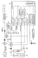
- Fig. 1 illustrates in block form an auxiliary battery life determining device according to Embodiment 1 of the present invention.
- reference numeral 1 denotes a main battery (a lead-acid battery); 2 denotes a switch; 3 and 4 denote reverse blocking diodes; 5 denotes a step-down circuit; 6 denotes an auxiliary battery that has a thermistor 6a, such as a lithium battery; 7 denotes a guard resistor; 8 denotes a reverse blocking diode; 9 denotes a switch; 10 denotes a dummy load; 11 denotes a switch; and 12 to 15 denote resistors.
- a main battery a lead-acid battery
- 2 denotes a switch
- 3 and 4 denote reverse blocking diodes
- 5 denotes a step-down circuit
- 6 denotes an auxiliary battery that has a thermistor 6a, such as a lithium battery
- 7 denotes a guard resistor
- 8 denote
- Reference numeral 16 denotes a microcomputer
- 17 denotes a switching circuit which, at the time of determining the lefetime of the auxiliary battery 6, turns ON the switches 9 and 11 (OFF the switch 2) to discharge a constant current from the auxiliary battery 6 to the dummy load 10
- 18 denotes a discharge time counter for measuring the time of discharge from the auxiliary battery
- 19 to 21 denote delay elements (inverter circuits).
- the switches 1, 9 and 11, the switching circuit 17, the discharge time counter 18 and the delay elements 19 to 21 constitute discharge means.
- Reference numeral 22 denotes a current sensor circuit formed by a voltage-current converter and an amplifier, for measuring the discharge current from the auxiliary battery 6; 23 denotes an A/D converter for A/D converting the discharge current from the auxiliary battery 6 measured by the current sensor circuit 22; 24 denotes an A/D converter for A/D converting the terminal voltage of the auxiliary battery 6; and 25 denotes an A/D converter for A/D converting the temperature of the auxiliary battery 6.
- the thermistor 6a, the resistors 12 to 15, the current sensor circuit 22 and the A/D converters 23 to 25 constitute measuring means.
- Reference numeral 26 denotes a lifetime decision circuit which calculates the depth of discharge of the auxiliary battery 6 from the results of conversions by the A/D converters and, when the depth of discharge exceeds a reference depth, turns ON a replacement timing indication LED 29;
- 27 denotes a characteristic storage part for storing discharge curves (discharge characteristics) of different depths of discharge;
- 28 denotes a remaining power estimating circuit which estimates the amount of power remaining in the auxiliary battery 6 from the results of conversion by the A/D converters 23 to 25;
- 29 denotes the replacement timing indication LED;
- 30 denotes a remaining power indicator for indicating the remaining power of the auxiliary battery 6.
- the lifetime decision circuit 26, the characteristic storage part 27, the remaining power estimating circuit 28, the replacement timing indication LED 29 and the remaining power indicator 30 constitute decision means.
- the switch 2 When the amount of power remaining in the main battery 1 is sufficient and no failures are found, the switch 2 is kept ON (the switches 9 and 11 OFF), providing therethrough a power supply from the main battery 1 to a real load.
- the switching circuit 17 turns OFF the switch 2 and ON the switch 9 (OFF the switch 11), through which power is supplied from the auxiliary battery 6 to the real load.
- auxiliary battery 6 normally out of use is also exhausted by self-discharge, it cannot be used in some instances even if switched from the main battery 1 in case of emergency.
- Embodiment 1 examines the life of the auxiliary battery 6 by periodically calculating he depth of discharge of the auxiliary battery 6.
- the switching circuit 17 To examine the lifetime of the auxiliary battery 6, the switching circuit 17 first turns OFF the switch 2, and until a predetermined discharge time elapses (for instance, 10 mS), it holds the switches 9 and 22 in the ON state, discharging therethrough a constant current (for example, a 5-A current) from the auxiliary battery 6 to the dummy load 10.
- a predetermined discharge time elapses for instance, 10 mS
- a constant current for example, a 5-A current
- the lifetime decision circuit 26 calculates, upon the start of discharge from the auxiliary battery 6, the depth of discharge of the auxiliary battery 6 from the results of conversion (the discharge current, terminal voltage and temperature of the auxiliary battery 6) by the A/D converters 23 to 25.
- the lifetime decision circuit 26 decides that the auxiliary battery 6 needs replacing (if it decides that no current is discharged to the real load for the minimum guaranteed time of operation (10 minutes, for instance)), and turns ON the replacement timing indication LED 29.
- the discharge time is 10 mS
- the discharge current is 5 A
- the nominal rate capacitance of the auxiliary battery 6 is 2200 mAh
- the discharge to the dummy load can be done 158400 times until the 10% reference depth of discharge is reached; assuming that the service life of the auxiliary battery 6 is five years, the discharge to the dummy load can be done 8.6 times per day. This means that the discharge to the dummy load is carried out every three hours, and this time interval affects the lifetime decision accuracy.
- the remaining power estimating circuit 28 Upon calculation of the depth of discharge of the auxiliary battery 6 by the lifetime decision circuit 26, the remaining power estimating circuit 28 refers to the discharge curves of different depths of discharge (see Fig. 2: It must be noted here, in particular, that the discharge characteristic (the discharge time) becomes worse with an increase in the depth of discharge), then estimates the amount of power remaining in the auxiliary battery 6 from the results of conversion (the discharge current, terminal voltage and temperature of the auxiliary battery 6) by the A/D converters 23 to 25, and indicates on the remaining power indicator 30 the estimated amount of power remaining in the auxiliary battery 6.
- the switching circuit 17 Upon expiration of the predetermined discharge time, the switching circuit 17 returns the switch 2 to the ON state and the switches 9 and 11 to the OFF state, providing a power supply from the main battery 1 to the real load.
- Embodiment 1 is adapted to calculate the depth of discharge of the auxiliary battery 6 and determine the lifetime of the auxiliary battery 6 based on the calculated depth of discharge, and hence it permits determination of the replacement timing of the auxiliary battery 6 and the remaining power thereof. This ensures replacement of the auxiliary battery 6 and hence excludes the possibility of the system becoming inoperative in emergencies.
- Embodiments 1 and 2 have been described to periodically connect the auxiliary battery 6 to the dummy load 10 for discharge thereto, it is also possible to employ a construction in which when the auxiliary battery 6 is supplying power to the real load (with the switch 2 held OFF and the switch 9 ON and the switch 11 OFF) in the event of a failure or disconnection of the main battery 1, the lifetime decision circuit 26 calculates the depth of discharge of the auxiliary battery 6 as in Embodiment 1 to thereby indicate the replacement timing, remaining power or useful time of the auxiliary battery 6.
- the auxiliary battery life determining device is suitable for use in an emergency reporting system or the like which employs, in addition to a main battery for normal use, an auxiliary battery for use in emergencies.
Landscapes
- Physics & Mathematics (AREA)
- General Physics & Mathematics (AREA)
- Secondary Cells (AREA)
- Charge And Discharge Circuits For Batteries Or The Like (AREA)
- Tests Of Electric Status Of Batteries (AREA)
Abstract
Description
Claims (9)
- An auxiliary life determining device comprising: discharge means for connecting an auxiliary battery to a dummy load to discharge a constant current from said auxiliary battery to said dummy load; measuring means for measuring the terminal voltage and temperature of said auxiliary battery when said discharge means causes the discharge of the constant current; and decision means for calculating the depth of discharge of said auxiliary battery from the measured results by said measuring means and for deciding the lifetime of said auxiliary battery based on said calculated depth of discharge.
- The auxiliary battery life determining device according to claim 1, wherein said decision means displays said auxiliary battery needs replacing when the depth of discharge of said auxiliary battery exceeds a reference depth of discharge.
- The auxiliary battery life determining device according to claim 1, wherein said decision means refers to discharge curves of different depths of discharge, then calculates the amount of power remaining in said auxiliary battery from -the-measured results by said measuring means, and displays the amount of power remaining in said auxiliary battery.
- The auxiliary battery life determining device according to claim 1, wherein said decision means refers to discharge curves of different depths of discharge, then calculates the useful time of said auxiliary battery from the measured results by said measuring means, and displays the useful time of said auxiliary battery.
- The auxiliary battery life determining device according to claim 1, wherein said discharge means periodically causes the discharge of the constant current until the number of times the constant current is discharged reaches a predetermined number of times.
- An auxiliary life determining device comprising: measuring means for measuring the discharge current, terminal voltage and temperature of an auxiliary battery connected to a real load; and decision means for calculating the depth of discharge of said auxiliary battery from the measured results by said measuring means and for deciding the lifetime of said auxiliary battery based on said calculated depth of discharge.
- The auxiliary battery life determining device according to claim 6, wherein said decision means displays said auxiliary battery needs replacing when the depth of discharge of said auxiliary battery exceeds a reference depth of discharge.
- The auxiliary battery life determining device according to claim 6, wherein said decision means refers to discharge curves of different depths of discharge, then calculates the amount of power remaining in said auxiliary battery from the measured results by said measuring means, and displays the amount of power remaining in said auxiliary battery.
- The auxiliary battery life determining device according to claim 6, wherein said decision means refers to discharge curves of different depths of discharge, then calculates the useful time of said auxiliary battery from the measured results by said measuring means, and displays the useful time of said auxiliary battery.
Applications Claiming Priority (1)
| Application Number | Priority Date | Filing Date | Title |
|---|---|---|---|
| PCT/JP2000/003733 WO2001094962A1 (en) | 2000-06-08 | 2000-06-08 | Device for judging life of auxiliary battery |
Publications (3)
| Publication Number | Publication Date |
|---|---|
| EP1278072A1 true EP1278072A1 (en) | 2003-01-22 |
| EP1278072A4 EP1278072A4 (en) | 2005-02-16 |
| EP1278072B1 EP1278072B1 (en) | 2007-05-02 |
Family
ID=11736131
Family Applications (1)
| Application Number | Title | Priority Date | Filing Date |
|---|---|---|---|
| EP00935592A Expired - Lifetime EP1278072B1 (en) | 2000-06-08 | 2000-06-08 | Device for judging life of auxiliary battery |
Country Status (4)
| Country | Link |
|---|---|
| US (1) | US6642719B1 (en) |
| EP (1) | EP1278072B1 (en) |
| DE (1) | DE60034708T2 (en) |
| WO (1) | WO2001094962A1 (en) |
Cited By (6)
| Publication number | Priority date | Publication date | Assignee | Title |
|---|---|---|---|---|
| NL1022497C2 (en) * | 2003-01-27 | 2004-08-03 | Sensite Solutions B V | Method and device comprising means for determining the available power of an electrical power source. |
| EP1482318A3 (en) * | 2003-05-29 | 2005-04-13 | Yuasa Battery (Uk) Limited | Battery life monitor and battery state of charge monitor |
| US7400149B2 (en) * | 2002-01-08 | 2008-07-15 | Siemens Aktiengesellschaft | Method for assessment of the state of batteries in battery-supported power supply systems |
| EP1775793A4 (en) * | 2004-08-05 | 2008-11-12 | Matsushita Electric Industrial Co Ltd | METHOD FOR DETERMINING THE LIFETIME OF NICKEL-HYDRIDE BATTERIES AND APPARATUS FOR DETERMINING THE LIFETIME |
| US7554330B2 (en) | 2003-02-24 | 2009-06-30 | Daimler Ag | Method for determining the deterioration of a battery |
| WO2014124733A1 (en) * | 2013-02-14 | 2014-08-21 | Audi Ag | Method for testing an energy store in a motor vehicle |
Families Citing this family (10)
| Publication number | Priority date | Publication date | Assignee | Title |
|---|---|---|---|---|
| JP2002330547A (en) * | 2001-04-27 | 2002-11-15 | Internatl Business Mach Corp <Ibm> | Electric apparatus for determining battery life, computer device, battery life determination system, battery, and battery life detection method |
| JP3681735B2 (en) * | 2003-05-21 | 2005-08-10 | 本田技研工業株式会社 | Charge / discharge control device for power storage device and charge / discharge control method |
| US7321521B2 (en) | 2004-07-02 | 2008-01-22 | Seagate Technology Llc | Assessing energy requirements for a refreshed device |
| US7081761B2 (en) * | 2004-07-14 | 2006-07-25 | General Motors Corporation | Ultracapacitor useful life prediction |
| US7177222B2 (en) * | 2005-03-04 | 2007-02-13 | Seagate Technology Llc | Reducing power consumption in a data storage system |
| US8519673B2 (en) * | 2006-06-30 | 2013-08-27 | Seagate Technology Llc | Arbitrating battery power calibration in a device that selects a battery power unit from a purality of selectable battery power units |
| JP4501946B2 (en) * | 2007-02-23 | 2010-07-14 | 日本電気株式会社 | Control program for disk array device and disk controller |
| US9325193B2 (en) | 2011-08-15 | 2016-04-26 | Shawn P. Kelly | Apparatus and method for accurate energy device state-of-charge (SoC) monitoring and control using real-time state-of-health (SoH) data |
| EP2764378B1 (en) * | 2011-08-15 | 2017-04-12 | Shawn P. Kelly | Apparatus and method for accurate energy device state-of-health (soh) monitoring |
| EP2839784B1 (en) * | 2012-11-16 | 2017-03-22 | Olympus Corporation | Bias-voltage generation device, and ultrasound diagnostic system |
Family Cites Families (24)
| Publication number | Priority date | Publication date | Assignee | Title |
|---|---|---|---|---|
| US3907398A (en) * | 1973-09-18 | 1975-09-23 | Jr James O Hebert | Load circuit and method |
| JPS5686039A (en) * | 1979-12-15 | 1981-07-13 | Matsushita Electric Works Ltd | Automatic lifetime monitor for backup storage battery |
| US4361809A (en) * | 1980-11-20 | 1982-11-30 | Ford Motor Company | Battery diagnostic method and apparatus |
| US4413221A (en) * | 1980-12-18 | 1983-11-01 | Christie Electric Corporation | Method and circuit for determining battery capacity |
| US4707795A (en) * | 1983-03-14 | 1987-11-17 | Alber Engineering, Inc. | Battery testing and monitoring system |
| JPS6095371A (en) | 1983-10-31 | 1985-05-28 | Matsushita Electric Works Ltd | Battery remaining quantity recognizing circuit |
| DE3573321D1 (en) * | 1984-06-30 | 1989-11-02 | Udo Kopmann | Device for controlling the charge state of rechargeable batteries |
| JPH01102881U (en) * | 1987-12-28 | 1989-07-11 | ||
| DE69030063T2 (en) * | 1989-12-11 | 1997-07-10 | Canon Kk | Battery residual charge determination arrangement |
| DE3942288C1 (en) * | 1989-12-21 | 1991-03-14 | Scheidt & Bachmann Gmbh, 4050 Moenchengladbach, De | |
| US5140269A (en) * | 1990-09-10 | 1992-08-18 | Champlin Keith S | Electronic tester for assessing battery/cell capacity |
| US5191291A (en) * | 1991-04-30 | 1993-03-02 | George Taylor | Method and apparatus for determining the performance capabilities of secondary batteries |
| FR2683634B1 (en) * | 1991-11-08 | 1995-07-13 | Paris Val De Marne Universite | METHOD FOR MEASURING THE STATE OF CHARGE OF A NICKEL-CADMIUM ACCUMULATOR, AND DEVICE FOR CARRYING OUT SAID METHOD. |
| JP3192005B2 (en) * | 1992-09-29 | 2001-07-23 | 株式会社ユアサコーポレーション | A method for measuring the remaining life of storage batteries for electric vehicles |
| FR2702885B1 (en) * | 1993-03-15 | 1995-04-21 | Alcatel Converters | System for monitoring the aging of a battery and method implemented in such a system. |
| JP3172977B2 (en) * | 1993-05-26 | 2001-06-04 | 富士重工業株式会社 | In-vehicle battery capacity meter |
| US5606243A (en) * | 1993-11-19 | 1997-02-25 | Nippon Soken, Inc. | Battery state judging apparatus |
| US5640150A (en) * | 1995-08-17 | 1997-06-17 | The United States Of America As Represented By The Secretary Of The Army | Resettable state-of-charge indicator for rechargeable batteries |
| JP3105802B2 (en) * | 1996-10-25 | 2000-11-06 | 東京電力株式会社 | Method for calculating remaining power of battery system using secondary battery and battery system using the same |
| JPH10153647A (en) * | 1996-11-26 | 1998-06-09 | Casio Comput Co Ltd | Battery level detection method |
| US6160380A (en) * | 1997-02-13 | 2000-12-12 | Nissan Motor Co., Ltd. | Method and apparatus of correcting battery characteristic and of estimating residual capacity of battery |
| JPH1186912A (en) * | 1997-09-08 | 1999-03-30 | Sanden Corp | Method for estimating lifetime of storage battery in low-temperature storage house, and low temperature storage house |
| JPH11271407A (en) | 1998-03-20 | 1999-10-08 | Seiko Instruments Inc | Method for detecting battery residual capacity, and portable electronic device and method for managing battery capacity thereof |
| AU5320599A (en) * | 1998-07-27 | 2000-02-21 | Midtronics, Inc. | Apparatus and method for carrying out diagnostic tests on batteries and for rapidly charging batteries |
-
2000
- 2000-06-08 WO PCT/JP2000/003733 patent/WO2001094962A1/en not_active Ceased
- 2000-06-08 EP EP00935592A patent/EP1278072B1/en not_active Expired - Lifetime
- 2000-06-08 DE DE60034708T patent/DE60034708T2/en not_active Expired - Fee Related
- 2000-06-08 US US10/031,116 patent/US6642719B1/en not_active Expired - Fee Related
Cited By (8)
| Publication number | Priority date | Publication date | Assignee | Title |
|---|---|---|---|---|
| US7400149B2 (en) * | 2002-01-08 | 2008-07-15 | Siemens Aktiengesellschaft | Method for assessment of the state of batteries in battery-supported power supply systems |
| NL1022497C2 (en) * | 2003-01-27 | 2004-08-03 | Sensite Solutions B V | Method and device comprising means for determining the available power of an electrical power source. |
| EP1462814A1 (en) * | 2003-01-27 | 2004-09-29 | Sensite Solutions B.V. | Method for and arrangement comprising means for determining the available power capacity of an electric power supply |
| US7161327B2 (en) | 2003-01-27 | 2007-01-09 | Sensite Solutions, B.V. | Method for and arrangement comprising means for determining the available power capacity of an electric power supply |
| US7554330B2 (en) | 2003-02-24 | 2009-06-30 | Daimler Ag | Method for determining the deterioration of a battery |
| EP1482318A3 (en) * | 2003-05-29 | 2005-04-13 | Yuasa Battery (Uk) Limited | Battery life monitor and battery state of charge monitor |
| EP1775793A4 (en) * | 2004-08-05 | 2008-11-12 | Matsushita Electric Industrial Co Ltd | METHOD FOR DETERMINING THE LIFETIME OF NICKEL-HYDRIDE BATTERIES AND APPARATUS FOR DETERMINING THE LIFETIME |
| WO2014124733A1 (en) * | 2013-02-14 | 2014-08-21 | Audi Ag | Method for testing an energy store in a motor vehicle |
Also Published As
| Publication number | Publication date |
|---|---|
| EP1278072B1 (en) | 2007-05-02 |
| DE60034708T2 (en) | 2008-01-31 |
| WO2001094962A1 (en) | 2001-12-13 |
| EP1278072A4 (en) | 2005-02-16 |
| DE60034708D1 (en) | 2007-06-14 |
| US6642719B1 (en) | 2003-11-04 |
Similar Documents
| Publication | Publication Date | Title |
|---|---|---|
| US6642719B1 (en) | Device for judging life of auxiliary battery | |
| EP0713101B1 (en) | Remaining battery capacity meter and method for computing remaining capacity | |
| JP5225559B2 (en) | Battery pack abnormality determination method and battery pack | |
| US8427003B2 (en) | Electric power supply device | |
| JP4817647B2 (en) | Secondary battery life judgment method. | |
| US9800066B2 (en) | Electricity distribution device, and controlling method for battery pack | |
| US8198863B1 (en) | Model-based battery fuel gauges and methods | |
| KR0146269B1 (en) | System for supplying power to an apparatus and method for the lifetime and capacity of a power-storage | |
| US20110187329A1 (en) | Battery condition detector, battery pack including same, and battery condition detecting method | |
| US8736232B2 (en) | Full charge capacity correction circuit, charging system, battery pack and full charge capacity correction method | |
| US20140042828A1 (en) | Electric storage apparatus and power path switch apparatus | |
| US6255801B1 (en) | System and method for assessing a capacity of a battery and power plant incorporating the same | |
| JPH08506477A (en) | Device and method for dynamic adjustment and monitoring of a storage battery pack | |
| WO2011048471A1 (en) | Power supply apparatus | |
| JP2010200574A (en) | Self-diagnosis circuit and power supply | |
| US20030085690A1 (en) | Rechargeable battery device equipped with life determination function | |
| CN103718054A (en) | Device for monitoring an electrical accumulation battery and associated method | |
| WO2008072436A1 (en) | Secondary battery deterioration judging device and backup power supply | |
| US9148025B2 (en) | System and method for a rechargeable battery | |
| JP3732465B2 (en) | Railway vehicle storage battery status monitoring device | |
| JP2008298643A (en) | Method of detecting abnormality in internal current consumption of packed battery | |
| JP2008196853A (en) | Storage battery state measuring device, storage battery deterioration determination method, storage battery deterioration determination program | |
| JP2000184615A (en) | Battery management device and battery pack used for backup power supply | |
| JP5009258B2 (en) | Storage battery capacity estimation device and storage battery capacity estimation method | |
| KR19980079177A (en) | Portable computer and remaining power display method with voltage display function of rechargeable battery |
Legal Events
| Date | Code | Title | Description |
|---|---|---|---|
| PUAI | Public reference made under article 153(3) epc to a published international application that has entered the european phase |
Free format text: ORIGINAL CODE: 0009012 |
|
| 17P | Request for examination filed |
Effective date: 20020207 |
|
| AK | Designated contracting states |
Kind code of ref document: A1 Designated state(s): AT BE CH CY DE DK ES FI FR GB GR IE IT LI LU MC NL PT SE |
|
| RBV | Designated contracting states (corrected) |
Designated state(s): DE |
|
| A4 | Supplementary search report drawn up and despatched |
Effective date: 20050103 |
|
| 17Q | First examination report despatched |
Effective date: 20050401 |
|
| RAP1 | Party data changed (applicant data changed or rights of an application transferred) |
Owner name: MITSUBISHI DENKI KABUSHIKI KAISHA |
|
| GRAP | Despatch of communication of intention to grant a patent |
Free format text: ORIGINAL CODE: EPIDOSNIGR1 |
|
| GRAS | Grant fee paid |
Free format text: ORIGINAL CODE: EPIDOSNIGR3 |
|
| GRAA | (expected) grant |
Free format text: ORIGINAL CODE: 0009210 |
|
| AK | Designated contracting states |
Kind code of ref document: B1 Designated state(s): DE |
|
| REF | Corresponds to: |
Ref document number: 60034708 Country of ref document: DE Date of ref document: 20070614 Kind code of ref document: P |
|
| PLBE | No opposition filed within time limit |
Free format text: ORIGINAL CODE: 0009261 |
|
| STAA | Information on the status of an ep patent application or granted ep patent |
Free format text: STATUS: NO OPPOSITION FILED WITHIN TIME LIMIT |
|
| 26N | No opposition filed |
Effective date: 20080205 |
|
| PGFP | Annual fee paid to national office [announced via postgrant information from national office to epo] |
Ref country code: DE Payment date: 20080626 Year of fee payment: 9 |
|
| PG25 | Lapsed in a contracting state [announced via postgrant information from national office to epo] |
Ref country code: DE Free format text: LAPSE BECAUSE OF NON-PAYMENT OF DUE FEES Effective date: 20100101 |