EP1278051B1 - Linsenanordnung für Bewegungssensor - Google Patents
Linsenanordnung für Bewegungssensor Download PDFInfo
- Publication number
- EP1278051B1 EP1278051B1 EP02012842A EP02012842A EP1278051B1 EP 1278051 B1 EP1278051 B1 EP 1278051B1 EP 02012842 A EP02012842 A EP 02012842A EP 02012842 A EP02012842 A EP 02012842A EP 1278051 B1 EP1278051 B1 EP 1278051B1
- Authority
- EP
- European Patent Office
- Prior art keywords
- movement sensor
- lenses
- lens
- lens arrangement
- infrared
- Prior art date
- Legal status (The legal status is an assumption and is not a legal conclusion. Google has not performed a legal analysis and makes no representation as to the accuracy of the status listed.)
- Expired - Lifetime
Links
Images

Classifications
-
- G—PHYSICS
- G01—MEASURING; TESTING
- G01J—MEASUREMENT OF INTENSITY, VELOCITY, SPECTRAL CONTENT, POLARISATION, PHASE OR PULSE CHARACTERISTICS OF INFRARED, VISIBLE OR ULTRAVIOLET LIGHT; COLORIMETRY; RADIATION PYROMETRY
- G01J5/00—Radiation pyrometry, e.g. infrared or optical thermometry
- G01J5/0022—Radiation pyrometry, e.g. infrared or optical thermometry for sensing the radiation of moving bodies
-
- G—PHYSICS
- G01—MEASURING; TESTING
- G01J—MEASUREMENT OF INTENSITY, VELOCITY, SPECTRAL CONTENT, POLARISATION, PHASE OR PULSE CHARACTERISTICS OF INFRARED, VISIBLE OR ULTRAVIOLET LIGHT; COLORIMETRY; RADIATION PYROMETRY
- G01J5/00—Radiation pyrometry, e.g. infrared or optical thermometry
- G01J5/0022—Radiation pyrometry, e.g. infrared or optical thermometry for sensing the radiation of moving bodies
- G01J5/0025—Living bodies
-
- G—PHYSICS
- G01—MEASURING; TESTING
- G01J—MEASUREMENT OF INTENSITY, VELOCITY, SPECTRAL CONTENT, POLARISATION, PHASE OR PULSE CHARACTERISTICS OF INFRARED, VISIBLE OR ULTRAVIOLET LIGHT; COLORIMETRY; RADIATION PYROMETRY
- G01J5/00—Radiation pyrometry, e.g. infrared or optical thermometry
- G01J5/02—Constructional details
- G01J5/07—Arrangements for adjusting the solid angle of collected radiation, e.g. adjusting or orienting field of view, tracking position or encoding angular position
-
- G—PHYSICS
- G01—MEASURING; TESTING
- G01J—MEASUREMENT OF INTENSITY, VELOCITY, SPECTRAL CONTENT, POLARISATION, PHASE OR PULSE CHARACTERISTICS OF INFRARED, VISIBLE OR ULTRAVIOLET LIGHT; COLORIMETRY; RADIATION PYROMETRY
- G01J5/00—Radiation pyrometry, e.g. infrared or optical thermometry
- G01J5/02—Constructional details
- G01J5/08—Optical arrangements
-
- G—PHYSICS
- G01—MEASURING; TESTING
- G01J—MEASUREMENT OF INTENSITY, VELOCITY, SPECTRAL CONTENT, POLARISATION, PHASE OR PULSE CHARACTERISTICS OF INFRARED, VISIBLE OR ULTRAVIOLET LIGHT; COLORIMETRY; RADIATION PYROMETRY
- G01J5/00—Radiation pyrometry, e.g. infrared or optical thermometry
- G01J5/02—Constructional details
- G01J5/08—Optical arrangements
- G01J5/0806—Focusing or collimating elements, e.g. lenses or concave mirrors
-
- G—PHYSICS
- G08—SIGNALLING
- G08B—SIGNALLING SYSTEMS, e.g. PERSONAL CALLING SYSTEMS; ORDER TELEGRAPHS; ALARM SYSTEMS
- G08B13/00—Burglar, theft or intruder alarms
- G08B13/18—Actuation by interference with heat, light, or radiation of shorter wavelength; Actuation by intruding sources of heat, light, or radiation of shorter wavelength
- G08B13/189—Actuation by interference with heat, light, or radiation of shorter wavelength; Actuation by intruding sources of heat, light, or radiation of shorter wavelength using passive radiation detection systems
- G08B13/19—Actuation by interference with heat, light, or radiation of shorter wavelength; Actuation by intruding sources of heat, light, or radiation of shorter wavelength using passive radiation detection systems using infrared-radiation detection systems
- G08B13/193—Actuation by interference with heat, light, or radiation of shorter wavelength; Actuation by intruding sources of heat, light, or radiation of shorter wavelength using passive radiation detection systems using infrared-radiation detection systems using focusing means
Definitions
- the present invention relates to a motion sensor according to the preamble of claim 1.
- Movement or presence sensors are often used for monitoring purposes, but also for the automatic control of actuators arranged in a room, such as lighting equipment, heating equipment, air conditioning or the like. -. These sensors are used e.g. to detect the presence of a person within a room and, depending thereon, to adjust the lighting or temperature control in the room. Sensors are also used to automatically activate doors or escalators.
- Active sensors themselves generate a signal and check whether this signal is influenced by an object located in the detection area of the sensor. These include, for example, photoelectric barriers.
- passive sensors detect the signals generated by an object to be detected, but they themselves do not transmit signals.
- the present application relates to so-called.
- Passive infrared sensors PIR or passive infrared sensors. These detect the infrared radiation emitted by objects and for this purpose have one or more infrared-sensitive sensor elements and a lens arrangement arranged in front of them.
- the lens arrangement maps the detection range detected by the sensor onto the infrared-sensitive sensor element, the presence of a moving person being detected by monitoring the time profile of the sensor signal.
- Presence or presence sensors are known whose task is to detect the presence or movement of a person within a room.
- the sensors are arranged, for example, on a ceiling of the room, wherein the area to be monitored by the sensor is imaged onto an infrared-sensitive sensor element with the aid of a dome-shaped lens arrangement arranged on the front side of the sensor.
- these known sensors have the property that they are larger for nearby areas Sensitivity than for more remote areas, that is, that the spatial resolution for areas below the sensor is much finer than for edge areas of the room.
- the present invention is therefore based on the object of specifying a novel sensor, in which the presence of objects emitting infrared radiation can be reliably detected in more remote areas, this advantageous property of the sensor to be achieved in a simple manner.
- the measure according to the invention ensures that objects removed from the motion sensor can be detected with the same reliability as objects located directly in the vicinity of the motion sensor.
- the detected by the motion sensor detection area is substantially rectangular, preferably square.
- the motion sensor 1 is in the in Fig. 1 example shown attached to the ceiling 2 of a room to be monitored.
- Part of the motion sensor 1 is a sensor housing 16, which is arranged sunk in the ceiling 2 and includes an IR-sensitive sensor described in more detail later and the further electronics of the motion sensor 1.
- At the front or bottom of the housing 16 is a dome-shaped cover 6 with a lens assembly 7, which images the detection area 3 on the infrared-sensitive sensor.
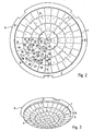
- the detected by the motion sensor 1 detection area 3 is square, which is achieved by a particular embodiment of the lens assembly 7. This will be explained below with reference to FIGS. 2 and 3 which illustrate two variants of a lens arrangement 7.
- Both lens assemblies 7 are divided into a plurality of individual fields, each forming a single lens 8.
- the entire domed or dome-shaped lens arrangement 7 consists of an infrared-transparent plastic, the individual lenses 8 being designed as so-called Fresnel lenses.
- the arrangement and design of the individual lenses 8 is such that they each map a portion 4 of the entire detection area 3 of the motion sensor 1 on the IR-sensitive sensor, which in Fig. 1 is shown.
- the subregions 4 are arranged uniformly distributed within the detection region 3 due to the configuration of the lens arrangement and in each case have the same size.
- a section 4 is also in two again Cutouts 5a, 5b divided, wherein the movement sensor 1 is formed such that the movement of a heat radiation emitting object from a cutout 5a in the other section 5b of the portion 4 is detected.
- the individual lenses 8 of the lens arrangement 7 are arranged in concentric circles around the center of the lens arrangement 7, the arrangement being symmetrical for each quarter of the lens arrangement 7.
- the lenses 8 are designed differently according to their arrangement.
- the cross-section of the lenses 8 is such that the cross-eyed optical centers 9 of all the lenses 8 viewed in plan view are arranged in a uniform grid structure corresponding to the arrangement of the subregions 4.
- the optical center of a lens is understood to mean the point at which all the rays intersect, which have the same direction before and after the lens.
- Fig. 2 The assignment of the optical centers to the lenses can Fig. 2 are taken, in which the arranged in the lower left quarter lenses and optical centers are numbered separately.
- the individual lenses are additionally designated with a "B", while an "A" was additionally added to the numbers for the optical centers.
- the optical center 10A of the lens 10B located in the outer ring is shifted toward the center of the lens array 7 so that it is already in the area of the lens 9B.
- the displacement of the optical centers of all lenses is such as to result in the regular arrangement of the optical centers, whereby the uniform division of the detection area according to the invention is obtained.
- FIG. 2 shown in plan view of the first variant of the lens assembly 7 have all the individual lenses 8 except for the lens arranged in the middle of a trapezoidal shape, the middle lens, however, is octagonal.
- the middle lens is octagonal.
- Perspective illustrated second variant differs from the first variant in that the individual lenses have 8 rounded outer sides and the lens arranged in the center is circular.
- the arrangement of the lenses 8 in concentric circles is identical in both variants.
- the individual lenses 8 are formed so that their optical centers 9 are arranged in a uniform grid on the spherical surface.
- Fig. 4 schematically shows the structure of the infrared sensor 10 and its interaction with two arranged in front of the lenses 13 and 14.
- the infrared sensor 10 consists of two adjacently arranged infrared-sensitive sensor elements 11 and 12.
- the arranged in front of the sensor 10 lens 13 forms - as shown - two adjacent areas 13a and 13b on the infrared sensor 10 from, in particular the area 13a on the lower sensor element 11 and the area 13b on the upper sensor element 12. Both areas 13a and 13b, the two sections 5a, 5b of a Fig. 1
- the detected by the two sensor elements 10 and 11 signals are fed to an evaluation unit 15, for example, the sensor element 11 generates a positive signal and the sensor element 12 generates a negative signal.
- the sensor 10 If there is then a light source emitting the infrared radiation in the subregion 13a, the sensor 10 as a whole generates a positive signal. If the IR source now moves from the partial area 13a into the partial area 13b, then the sensor signal drops from a maximum value to a minimum value. This change in the signal is interpreted by the evaluation unit 15 as a movement or presence of an object emitting thermal radiation in the subregion of the detection area formed by the cutouts 13a, 13b. In the same way, the presence or movement of an object located in the region formed by the regions 14a, 14b is detected by the lens 14. This operation of such a passive infrared detector (PIR detector) is well known and will therefore not be further explained.
- PIR detector passive infrared detector
- each lens 9 basically forms an equally large subregion 4 of the entire detection region 3 on the infrared sensor. This ensures that the spatial resolution of the sensor 1 over the entire detection area 3 is substantially constant.
- the lenses may also be designed such that the sensitivity of the sensor 1 for each portion 4 is substantially equal. That is, the signals generated by the infrared sensor 10 are basically the same, regardless of whether the source that emits the heat radiation, in a subregion 4, which is located directly below the sensor 1 or in a partial area, the am Edge of the detection area 3 is located. As a result, a motion sensor is achieved with a homogeneous resolution over the entire detection range.
- the present invention is characterized in that the desired homogeneous resolution of the motion sensor over its entire detection range is achieved only by a suitable embodiment of the lens arrangement. As a result, an optimal and reliable operation of the motion sensor is achieved by a relatively simple measure.
Landscapes
- Physics & Mathematics (AREA)
- General Physics & Mathematics (AREA)
- Spectroscopy & Molecular Physics (AREA)
- Geophysics And Detection Of Objects (AREA)
- Photometry And Measurement Of Optical Pulse Characteristics (AREA)
- Instruments For Viewing The Inside Of Hollow Bodies (AREA)
- Studio Devices (AREA)
- Optical Transform (AREA)
Description
- Die vorliegende Erfindung betrifft einen Bewegungssensor nach dem Oberbegriff des Anspruches 1.
- Bewegungs- oder Anwesenheitssensoren werden außer zu Überwachungszwecken oftmals auch zur automatischen Steuerung von in einem Raum angeordneten Aktoren, wie beispielsweise Beleuchtungseinrichtungen, Heizungseinrichtungen, Klimaanlagen oder dgl. - verwendet. Diese Sensoren dienen z.B. dazu, die Anwesenheit einer Person innerhalb eines Raumes festzustellen und anhängig davon die Beleuchtung oder Temperaturregelung in dem Raum einzustellen. Auch zur automatischen Aktivierung von Türen oder Rolltreppen finden Sensoren Verwendung.
- Hierbei ist zu unterscheiden zwischen sog. aktiven und passiven Sensoren. Aktive Sensoren erzeugen selbst ein Signal und überprüfen, ob dieses Signal durch ein in dem Detektionsbereich des Sensors befindliches Objekt beeinflußt wird. Hierunter fallen beispielsweise Lichtschranken. Im Gegensatz dazu erfassen passive Sensoren die von einem zu erkennenden Objekt erzeugten Signale, sie senden selbst allerdings keine Signale aus.
- Die vorliegende Anmeldung betrifft sog. Passive Infrarot-Sensoren (PIR- bzw. Passiv-Infrared-Sensoren). Diese erfassen die von Objekten emittierte Infrarotstahlung und weisen hierfür ein oder mehrere infrarot-empfindliche Sensorelemente sowie eine davor angeordnete Linsenanordnung auf. Die Linsenanordnung bildet den von dem Sensor erfaßten Detektionsbereich auf das infrarot-empfindliche Sensorelement ab, wobei durch eine Überwachung des zeitlichen Verlaufs des Sensorsignales die Anwesenheit einer sich bewegenden Person festgestellt wird.
- Es sind Anwesenheits- oder Präsenzsensoren bekannt, deren Aufgabe darin besteht, die Anwesenheit oder Bewegung einer Person innerhalb eines Raumes zu erkennen. Hierzu sind die Sensoren beispielsweise an einer Decke des Raumes angeordnet, wobei mit Hilfe einer an der Vorderseite des Sensors angeordneten kalottenförmigen Linsenanordnung der von dem Sensor zu überwachende Bereich auf ein infrarotempfindliches Sensorelement abgebildet wird. Diese bekannten Sensoren haben allerdings die Eigenschaft, daß sie für naheliegende Bereiche eine größere Empfindlichkeit aufweisen als für entferntere Bereiche, d.h., daß die räumliche Auflösung für Bereiche unterhalb des Sensors wesentlich feiner ist als für Randbereiche des Raumes.
- Modernere Bewegungssensoren sind aus den Veröffentlichungen
JP 09 230060 A US 5,187,360 ,JP 02 311779 A EP 0 542 170 A2 undEP 0 666 551 A1 bekannt. Diese Sensoren sind derart ausgestaltet, dass sie auch entfernter liegende Objekte mit einer gewissen Zuverlässigkeit zu detektieren vermögen. Diese Eigenschaft wird durch unterschiedlichste Maßnahmen erreicht, welche zum Teil sehr aufwendig sind und sich in den Produktionskosten für die Sensoren niederschlagen. - Der vorliegenden Erfindung liegt deshalb die Aufgabe zugrunde, einen neuartigen Sensor anzugeben, bei dem auch die Anwesenheit von Infrarot-Strahlung emittierenden Objekten in entfernter liegender Bereichen zuverlässig erkannt werden kann, wobei diese vorteilhafte Eigenschaft des Sensors auf einfache Weise erreicht werden soll.
- Diese Aufgabe wird durch einen Bewegungssensor, der die Merkmale des Anspruches 1 aufweist, gelöst.
- Durch die erfindungsgemäße Maßnahme wird gewährleistet, daß von dem Bewegungssensor entferntere Objekte mit der gleichen Zuverlässigkeit erkannt werden können, wie sich unmittelbar in der Nähe des Bewegungssensors befindende Objekte.
- Der von dem Bewegungssensor erfaßte Detektionsbereich ist im wesentlichen rechteckig, vorzugsweise quadratisch.
- Im folgenden soll die Erfindung anhand der beiliegenden Zeichnung näher erläutert werden. Es zeigen:
- Fig. 1
- den erfindungsgemäßen Bewegungssensor in perspektivischer Darstellung;
- Fig. 2
- eine erste Variante einer erfindungsgemäßen Linsenanordnung in Aufsicht;
- Fig. 3
- eine zweite Variante einer Linsenanordnung in perspektivischer Darstellung; und
- Fig. 4
- eine schematische Darstellung des Infrarot-Sensors mit zwei davor angeordneten Linsen.
- Der Bewegungssensor 1 ist in dem in
Fig. 1 dargestellten Beispiel an der Decke 2 eines zu überwachenden Raumes befestigt. Bestandteil des Bewegungssensors 1 ist ein Sensorgehäuse 16, welches in der Decke 2 versenkt angeordnet ist und einen noch später ausführlicher beschriebenen IR-empfindlichen Sensor sowie die weitere Elektronik des Bewegungssensors 1 beinhaltet. An der Vorder- bzw. Unterseite des Gehäuses 16 befindet sich eine kalottenförmige Abdeckung 6 mit einer Linsenanordnung 7, die den Detektionsbereich 3 auf den infrarot-empfindlichen Sensor abbildet. - Im dargestellten Beispiel ist der von dem Bewegungssensor 1 erfaßte Detektionsbereich 3 quadratisch, was durch eine besondere Ausgestaltung der Linsenanordnung 7 erreicht wird. Dies soll im folgenden anhand der
Fig. 2 und 3 erläutert werden, die zwei Varianten einer Linsenanordnung 7 zeigen. - Beide Linsenanordnungen 7 sind dabei in eine Vielzahl von Einzelfeldern unterteilt, die jeweils eine einzelne Linse 8 bilden. Die gesamte dom- bzw. kuppelförmige Linsenanordnung 7 besteht aus einem infrarot-transparenten Kunststoff, wobei die einzelnen Linsen 8 als sog. Fresnel-Linsen ausgebildet sind.
- Die Anordnung und Ausgestaltung der einzelnen Linsen 8 ist derart, daß sie jeweils einen Teilbereich 4 des gesamten Detektionsbereichs 3 des Bewegungssensors 1 auf den IR-empfindlichen Sensor abbilden, was in
Fig. 1 dargestellt ist. Insbesondere ist zu beachten, daß die Teilbereiche 4 aufgrund der Ausgestaltung der Linsenanordnung innerhalb des Detektionsbereichs 3 gleichmäßig verteilt angeordnet sind und jeweils die gleiche Größe aufweisen. Ein Teilbereich 4 ist darüber hinaus nochmals in zwei Ausschnitte 5a, 5b unterteilt, wobei der Bewegungssensor 1 derart ausgebildet ist, daß die Bewegung eines Wärmestrahlung emittierenden Objekts von einem Ausschnitt 5a in den anderen Ausschnitt 5b des Teilbereichs 4 erkannt wird. - Um die in
Fig. 1 dargestellte gleichmäßige Abbildung der Teilbereiche 3 auf den IR-empfindlichen Sensor zu erzielen, sind die einzelnen Linsen 8 der Linsenanordnung 7 in um das Zentrum der Linsenanordnung 7 konzentrisch verlaufenden Kreisen angeordnet, wobei die Anordnung für jedes Viertel der Linsenanordnung 7 symmetrisch ist. Darüber hinaus ist von Bedeutung, daß die Linsen 8 entsprechend ihrer Anordnung unterschiedlich gestaltet sind. Insbesondere ist der Querschnitt der Linsen 8 derart, daß die mit einem Kreuz dargestellten optischen Zentren 9 aller Linsen 8 in Aufsicht betrachtet in einer gleichmäßigen Gitterstruktur, die der Anordnung der Teilbereiche 4 entspricht, angeordnet sind. Als das optische Zentrum einer Linse wird dabei der Punkt verstanden, in dem sich alle Strahlen schneiden, die vor und nach der Linse die gleiche Richtung haben. - Die Zuordnung der optischen Zentren zu den Linsen kann
Fig. 2 entnommen werden, bei der die in dem unteren linken Viertel angeordneten Linsen und optischen Zentren gesondert numeriert sind. Die einzelnen Linsen werden dabei zusätzlich mit einem "B" bezeichnet, während an die Nummern für die optischen Zentren zusätzlich ein "A" angefügt wurde. Beispielsweise ist das optische Zentrum 10A der in dem äußeren Ring befindlichen Linse 10B derart zum Zentrum der Linsenanordnung 7 hin verschoben, daß es sich bereits in dem Bereich der Linse 9B befindet. Die Verschiebung der optischen Zentren aller Linsen ist derart, daß sich letztendlich die regelmäßige Anordnung der optischen Zentren ergibt, wodurch die erfindungsgemäße gleichmäßige Aufteilung des Detektionsbereichs erhalten wird. - Bei der in
Fig. 2 in Aufsicht dargestellten ersten Variante der Linsenanordnung 7 besitzen alle Einzellinsen 8 mit Ausnahme der in der Mitte angeordneten Linse eine Trapezform, die mittlere Linse ist hingegen achteckig. Die inFig. 3 perspektivisch dargestellte zweite Variante unterscheidet sich von der ersten Variante dadurch, daß die einzelnen Linsen 8 abgerundete Außenseiten haben und die in Zentrum angeordnete Linse kreisförmig ist. Die Anordnung der Linsen 8 in konzentrischen Kreisen ist allerdings bei beiden Varianten identisch. Ferner sind auch bei der Variante inFig. 3 die einzelnen Linsen 8 derart ausgebildet, daß ihre optischen Zentren 9 in einem gleichmäßigen Gitter auf der sphärischen Oberfläche angeordnet sind. -
Fig. 4 zeigt schematisch den Aufbau des Infrarot-Sensors 10 sowie dessen Zusammenwirken mit zwei davor angeordneten Linsen 13 und 14. Der Infrarot-Sensor 10 besteht aus zwei nebeneinander angeordneten infrarot-empfindlichen Sensorelementen 11 und 12. Die vor dem Sensor 10 angeordnete Linse 13 bildet dann - wie dargestellt - zwei benachbarte Bereiche 13a und 13b auf den Infrarot-Sensor 10 ab, insbesondere den Bereich 13a auf das untere Sensorelement 11 und den Bereich 13b auf das obere Sensorelement 12. Beide Bereiche 13a und 13b stellen die zwei Ausschnitte 5a, 5b eines inFig. 1 dargestellte Teilbereichs 4 dar. Die von den beiden Sensorelementen 10 und 11 erfaßten Signale werden einer Auswerteeinheit 15 zugeführt, wobei beispielsweise das Sensorelement 11 ein positives Signal und das Sensorelement 12 ein negatives Signal erzeugt. Befindet sich dann eine die Infrarot-Strahlung emittierende Lichtquelle in dem Teilbereich 13a, so erzeugt der Sensor 10 insgesamt ein positives Signal. Bewegt sich die IR-Quelle nun von dem Teilbereich 13a in den Teilbereich 13b, so fällt das Sensorsignal von einem Maximalwert auf einen Minimalwert. Diese Änderung des Signals wird von der Auswerteeinheit 15 als Bewegung bzw. Anwesenheit eines Wärmestrahlung emittierenden Objekts in dem durch die Ausschnitte 13a, 13b gebildeten Teilbereich des Detektionsbereichs interpretiert. In gleicher Weise wird durch die Linse 14 die Anwesenheit bzw. Bewegung eines in dem durch die Bereich 14a, 14b gebildeten Teilbereichs befindlichen Objekts erfaßt. Diese Funktionsweise eines derartigen passiven Infrarot-Detektors (PIR-Detektors) ist allgemein bekannt und wird daher nicht weiter erläutert. - Wesentlich ist, daß die Linsen 9 der Linsenanordnung 7 derart angeordnet und ausgebildet sind, daß - wie in
Fig. 1 dargestellt ist - die den einzelnen Linsen zugeordneten Teilbereiche 4 innerhalb des Detektionsbereiches 3 gleichmäßig verteilt angeordnet sind. Dies bedeutet, jede Linse 9 bildet grundsätzlich einen gleich großen Teilbereich 4 des gesamten Detektionsbereichs 3 auf dem Infrarot-Sensor ab. Hierdurch wird erreicht, daß die räumliche Auflösung des Sensors 1 über den gesamten Detektionsbereich 3 im wesentlichen konstant ist. Die Linsen können ferner derart ausgestaltet sein, daß die Sensitivität des Sensors 1 für jeden Teilbereich 4 im wesentlichen gleich groß ist. D.h., die von dem Infrarot-Sensor 10 erzeugten Signale sind grundsätzlich gleich hoch, unabhängig davon, ob sich die Quelle, die die Wärmestrahlung emittiert, in einem Teilbereich 4 befindet, der direkt unterhalb des Sensors 1 angeordnet ist oder in einem Teilbereich, der am Rand des Detektionsbereichs 3 liegt. Hierdurch wird ein Bewegungssensor mit einer über den gesamten Erfassungsbereich homogenen Auflösung erzielt. - Die vorliegende Erfindung zeichnet sich dadurch aus, daß die angestrebte homogene Auflösung des Bewegungssensors über seinen gesamten Detektionsbereich lediglich durch eine geeignete Ausgestaltung der Linsenanordnung erzielt wird. Hierdurch wird durch eine verhältnismäßig einfach durchzuführende Maßnahme eine optimale und zuverlässige Funktionsweise des Bewegungssensors erreicht.
Claims (9)
- Bewegungssensor (1) zum Erfassen der Bewegung bzw. Anwesenheit von Wärmestrahlung emittierenden Objekten, aufweisend
zumindest zwei Infrarotsensoren (10) zum Erfassen einer innerhalb eines Detektionsbereiches (3) des Bewegungssensors (1) emittierten Infrarotstrahlung,
eine an die Infrarotsensoren (10) angeschlossene Auswerteeinheit (15) zum Auswerten der von den Infrarotsensoren (10) erfaßten Signale und
eine vor den Infrarotsensoren (10) angeordnete, kuppelförmige Linsenanordnung (7) mit einer Vielzahl von Linsen (8), die in um das Zentrum der Linsenanordnung (7) konzentrisch verlaufenden Kreisen angeordnet sind und jeweils einen bestimmten Teilbereich (4) des Detektionsbereichs (3) auf die Infrarotsensoren (10) abbilden,
wobei die optischen Zentren (9) der Linsen (8) derart zum Zentrum der Linsenanordnung (7) hin verschoben sind, daß das optische Zentrum wenigstens einer in einem äußeren Ring der Linsenanordnung (7) befindlichen Linse (8) sich bereits in dem Bereich einer weiter innen liegenden Linse (8) befindet und daß die optischen Zentren (9) in Aufsicht betrachtet in einer gleichmäßigen Gitterstruktur angeordnet sind und dementsprechend die räumliche Auflösung des Bewegungssensors (1) im wesentlichen über den gesamten Detektionsbereich (3) konstant ist. - Bewegungssensor nach Anspruch 1,
dadurch gekennzeichnet,
daß die von den Linsen (8) auf den Infrarotsensor (10) abgebildeten Teilbereiche (4) innerhalb des Detektionsbereichs (3) gleichmäßig verteilt angeordnet sind. - Bewegungssensor nach einem der vorherigen Ansprüche,
dadurch gekennzeichnet,
daß der Detektionsbereich (3) im wesentlichen rechteckig ist. - Bewegungssensor nach Anspruch 3,
dadurch gekennzeichnet,
daß der Detektionsbereich (3) im wesentlichen quadratisch ist. - Bewegungssensor nach einem der vorherigen Ansprüche,
dadurch gekennzeichnet,
daß die Linsen (8) der Linsenanordnung (7) durch Fresnel-Linsen gebildet werden. - Bewegungssensor nach einem der vorherigen Ansprüche,
dadurch gekennzeichnet,
daß die Linsenanordnung (7) aus IR-transparentem Kunststoff besteht. - Bewegungssensor nach einem der vorherigen Ansprüche,
dadurch gekennzeichnet,
daß der Infrarotsensor durch zwei nebeneinander angeordnete infrarotempfindliche Sensorelemente (11, 12) gebildet wird, wobei jede Linse (9) der Linsenanordnung (7) jeweils einen Ausschnitt (5a, 5b) eines Teilbereichs (4) auf ein Sensorelement (11, 12) abbildet. - Bewegungssensor nach einem der vorherigen Ansprüche,
dadurch gekennzeichnet,
daß die Linsenanordnung (7) in einer kalottenförmigen Abdeckung (6) des Infrarotsensors (1) angeordnet ist. - Bewegungssensor nach einem der vorherigen Ansprüche,
dadurch gekennzeichnet,
daß die Linsen (8) im wesentlichen trapezförmig sind.
Applications Claiming Priority (2)
| Application Number | Priority Date | Filing Date | Title |
|---|---|---|---|
| DE10134565A DE10134565A1 (de) | 2001-07-16 | 2001-07-16 | Bewegungssensor |
| DE10134565 | 2001-07-16 |
Publications (2)
| Publication Number | Publication Date |
|---|---|
| EP1278051A1 EP1278051A1 (de) | 2003-01-22 |
| EP1278051B1 true EP1278051B1 (de) | 2008-04-23 |
Family
ID=7691977
Family Applications (1)
| Application Number | Title | Priority Date | Filing Date |
|---|---|---|---|
| EP02012842A Expired - Lifetime EP1278051B1 (de) | 2001-07-16 | 2002-06-10 | Linsenanordnung für Bewegungssensor |
Country Status (3)
| Country | Link |
|---|---|
| EP (1) | EP1278051B1 (de) |
| AT (1) | ATE393380T1 (de) |
| DE (2) | DE10134565A1 (de) |
Families Citing this family (2)
| Publication number | Priority date | Publication date | Assignee | Title |
|---|---|---|---|---|
| DE202012101356U1 (de) * | 2012-04-13 | 2013-07-16 | Steinel Gmbh | Einbau-Passiv-Infrarot-Sensorvorrichtung |
| WO2018161724A1 (zh) * | 2017-03-09 | 2018-09-13 | 苏州欧普照明有限公司 | 一种基于热释电红外传感器的照明控制装置及系统 |
Family Cites Families (6)
| Publication number | Priority date | Publication date | Assignee | Title |
|---|---|---|---|---|
| CH657928A5 (de) * | 1981-11-25 | 1986-09-30 | Eltec Instr Ag | Anordnung fuer einen strahlungsdetektor mit mehreren sensorelementen und deren verwendung. |
| JP2843054B2 (ja) * | 1989-05-26 | 1999-01-06 | 松下電工株式会社 | 人体検出装置 |
| GB2251700B (en) * | 1990-11-30 | 1994-08-24 | Combined Optical Ind Ltd | Multiple array lens |
| DE4137560C1 (de) * | 1991-11-15 | 1993-02-25 | Abb Patent Gmbh, 6800 Mannheim, De | |
| DE59507450D1 (de) * | 1994-02-08 | 2000-01-27 | Merten Gmbh & Co Kg Geb | Infrarot-Bewegungsmelder |
| JP3669454B2 (ja) * | 1996-02-26 | 2005-07-06 | 松下電工株式会社 | 人体検知センサ |
-
2001
- 2001-07-16 DE DE10134565A patent/DE10134565A1/de not_active Ceased
-
2002
- 2002-06-10 DE DE50212133T patent/DE50212133D1/de not_active Expired - Lifetime
- 2002-06-10 EP EP02012842A patent/EP1278051B1/de not_active Expired - Lifetime
- 2002-06-10 AT AT02012842T patent/ATE393380T1/de active
Also Published As
| Publication number | Publication date |
|---|---|
| EP1278051A1 (de) | 2003-01-22 |
| ATE393380T1 (de) | 2008-05-15 |
| DE10134565A1 (de) | 2003-02-06 |
| DE50212133D1 (de) | 2008-06-05 |
Similar Documents
| Publication | Publication Date | Title |
|---|---|---|
| DE69731797T2 (de) | Gerät zum Feststellen der Zahl der Passanten | |
| EP2667218B1 (de) | Energiespar-3-D-Sensor | |
| EP1300691B1 (de) | Überwachungsverfahren und optoelektronischer Sensor | |
| EP1065521B1 (de) | Optoelektronisches Überwachungssystem | |
| EP1089245B1 (de) | Passiv-Infrarotmelder | |
| EP1040039A1 (de) | Adaptiver absoluter lenkwinkelsensor | |
| DE69738270T2 (de) | Erfassungssystem | |
| DE19758104B4 (de) | Adaptiver absoluter Lenkwinkelsensor | |
| DE102004047022A1 (de) | Vorrichtung zur Überwachung von Raumbereichen | |
| EP0361224A1 (de) | Infraroteindringdetektor | |
| EP0080114B1 (de) | Strahlungsdetektor mit mehreren Sensorelementen | |
| DE202013003722U1 (de) | Erfassungs-Vorrichtung zur Erfassung einer Erfassungszone | |
| EP4118405B1 (de) | Infrarotbewegungsmelder | |
| DE19517517B4 (de) | Passiv Infrarot Eindringdetektor | |
| EP1813961B1 (de) | Vorrichtung zur optoelektronischen Überwachung von Objekten | |
| DE102013007961A1 (de) | Optisches Messsystem für ein Fahrzeug | |
| DE102004005460A1 (de) | Optoelektronische Vorrichtung | |
| EP4363815A1 (de) | Optisches element für einen bewegungsmelder | |
| EP0817145A1 (de) | Bewegungsmelder zur Detektion von Wärmestrahlung abgebenden, beweglichen Objekten | |
| EP1278051A1 (de) | Linsenanordnung für Bewegungssensor | |
| EP1065522B1 (de) | Optoelektronisches Überwachungssystem | |
| EP2065732A2 (de) | Optischer Sensor und Verfahren zur Positionsbestimmung von Objekten | |
| DE102005011116A1 (de) | Vorrichtung zur Ansteuerung und/oder Überwachung eines Flügels | |
| EP1811427A1 (de) | Vorrichtung zur Überwachung eines Schutzfeldes | |
| DE102007036632B4 (de) | Optischer Sensor und Verfahren zum Nachweis von Objekten in einem Überwachungsbereich |
Legal Events
| Date | Code | Title | Description |
|---|---|---|---|
| PUAI | Public reference made under article 153(3) epc to a published international application that has entered the european phase |
Free format text: ORIGINAL CODE: 0009012 |
|
| AK | Designated contracting states |
Kind code of ref document: A1 Designated state(s): AT BE CH CY DE DK ES FI FR GB GR IE IT LI LU MC NL PT SE TR |
|
| AX | Request for extension of the european patent |
Free format text: AL;LT;LV;MK;RO;SI |
|
| 17P | Request for examination filed |
Effective date: 20030630 |
|
| AKX | Designation fees paid |
Designated state(s): AT BE CH CY DE DK ES FI FR GB GR IE IT LI LU MC NL PT SE TR |
|
| 17Q | First examination report despatched |
Effective date: 20040616 |
|
| RAP1 | Party data changed (applicant data changed or rights of an application transferred) |
Owner name: ZUMTOBEL STAFF GMBH |
|
| RAP1 | Party data changed (applicant data changed or rights of an application transferred) |
Owner name: ZUMTOBEL LIGHTING GMBH |
|
| GRAP | Despatch of communication of intention to grant a patent |
Free format text: ORIGINAL CODE: EPIDOSNIGR1 |
|
| GRAS | Grant fee paid |
Free format text: ORIGINAL CODE: EPIDOSNIGR3 |
|
| GRAA | (expected) grant |
Free format text: ORIGINAL CODE: 0009210 |
|
| AK | Designated contracting states |
Kind code of ref document: B1 Designated state(s): AT BE CH CY DE DK ES FI FR GB GR IE IT LI LU MC NL PT SE TR |
|
| REG | Reference to a national code |
Ref country code: GB Ref legal event code: FG4D Free format text: NOT ENGLISH |
|
| REG | Reference to a national code |
Ref country code: CH Ref legal event code: NV Representative=s name: BOHEST AG Ref country code: CH Ref legal event code: EP |
|
| REF | Corresponds to: |
Ref document number: 50212133 Country of ref document: DE Date of ref document: 20080605 Kind code of ref document: P |
|
| REG | Reference to a national code |
Ref country code: IE Ref legal event code: FG4D Free format text: LANGUAGE OF EP DOCUMENT: GERMAN |
|
| NLV1 | Nl: lapsed or annulled due to failure to fulfill the requirements of art. 29p and 29m of the patents act | ||
| PG25 | Lapsed in a contracting state [announced via postgrant information from national office to epo] |
Ref country code: PT Free format text: LAPSE BECAUSE OF FAILURE TO SUBMIT A TRANSLATION OF THE DESCRIPTION OR TO PAY THE FEE WITHIN THE PRESCRIBED TIME-LIMIT Effective date: 20080923 Ref country code: NL Free format text: LAPSE BECAUSE OF FAILURE TO SUBMIT A TRANSLATION OF THE DESCRIPTION OR TO PAY THE FEE WITHIN THE PRESCRIBED TIME-LIMIT Effective date: 20080423 Ref country code: FI Free format text: LAPSE BECAUSE OF FAILURE TO SUBMIT A TRANSLATION OF THE DESCRIPTION OR TO PAY THE FEE WITHIN THE PRESCRIBED TIME-LIMIT Effective date: 20080423 Ref country code: ES Free format text: LAPSE BECAUSE OF FAILURE TO SUBMIT A TRANSLATION OF THE DESCRIPTION OR TO PAY THE FEE WITHIN THE PRESCRIBED TIME-LIMIT Effective date: 20080803 |
|
| REG | Reference to a national code |
Ref country code: IE Ref legal event code: FD4D |
|
| BERE | Be: lapsed |
Owner name: ZUMTOBEL LIGHTING GMBH Effective date: 20080630 |
|
| PG25 | Lapsed in a contracting state [announced via postgrant information from national office to epo] |
Ref country code: DK Free format text: LAPSE BECAUSE OF FAILURE TO SUBMIT A TRANSLATION OF THE DESCRIPTION OR TO PAY THE FEE WITHIN THE PRESCRIBED TIME-LIMIT Effective date: 20080423 Ref country code: SE Free format text: LAPSE BECAUSE OF FAILURE TO SUBMIT A TRANSLATION OF THE DESCRIPTION OR TO PAY THE FEE WITHIN THE PRESCRIBED TIME-LIMIT Effective date: 20080723 Ref country code: MC Free format text: LAPSE BECAUSE OF NON-PAYMENT OF DUE FEES Effective date: 20080630 Ref country code: IE Free format text: LAPSE BECAUSE OF FAILURE TO SUBMIT A TRANSLATION OF THE DESCRIPTION OR TO PAY THE FEE WITHIN THE PRESCRIBED TIME-LIMIT Effective date: 20080423 |
|
| EN | Fr: translation not filed | ||
| PLBE | No opposition filed within time limit |
Free format text: ORIGINAL CODE: 0009261 |
|
| STAA | Information on the status of an ep patent application or granted ep patent |
Free format text: STATUS: NO OPPOSITION FILED WITHIN TIME LIMIT |
|
| PG25 | Lapsed in a contracting state [announced via postgrant information from national office to epo] |
Ref country code: BE Free format text: LAPSE BECAUSE OF NON-PAYMENT OF DUE FEES Effective date: 20080630 |
|
| 26N | No opposition filed |
Effective date: 20090126 |
|
| PG25 | Lapsed in a contracting state [announced via postgrant information from national office to epo] |
Ref country code: IT Free format text: LAPSE BECAUSE OF FAILURE TO SUBMIT A TRANSLATION OF THE DESCRIPTION OR TO PAY THE FEE WITHIN THE PRESCRIBED TIME-LIMIT Effective date: 20080423 |
|
| PG25 | Lapsed in a contracting state [announced via postgrant information from national office to epo] |
Ref country code: CY Free format text: LAPSE BECAUSE OF FAILURE TO SUBMIT A TRANSLATION OF THE DESCRIPTION OR TO PAY THE FEE WITHIN THE PRESCRIBED TIME-LIMIT Effective date: 20080423 Ref country code: LU Free format text: LAPSE BECAUSE OF NON-PAYMENT OF DUE FEES Effective date: 20080610 |
|
| PG25 | Lapsed in a contracting state [announced via postgrant information from national office to epo] |
Ref country code: TR Free format text: LAPSE BECAUSE OF FAILURE TO SUBMIT A TRANSLATION OF THE DESCRIPTION OR TO PAY THE FEE WITHIN THE PRESCRIBED TIME-LIMIT Effective date: 20080423 |
|
| PG25 | Lapsed in a contracting state [announced via postgrant information from national office to epo] |
Ref country code: GR Free format text: LAPSE BECAUSE OF FAILURE TO SUBMIT A TRANSLATION OF THE DESCRIPTION OR TO PAY THE FEE WITHIN THE PRESCRIBED TIME-LIMIT Effective date: 20080724 |
|
| PG25 | Lapsed in a contracting state [announced via postgrant information from national office to epo] |
Ref country code: FR Free format text: LAPSE BECAUSE OF FAILURE TO SUBMIT A TRANSLATION OF THE DESCRIPTION OR TO PAY THE FEE WITHIN THE PRESCRIBED TIME-LIMIT Effective date: 20090227 |
|
| REG | Reference to a national code |
Ref country code: CH Ref legal event code: PCAR Free format text: NEW ADDRESS: HOLBEINSTRASSE 36-38, 4051 BASEL (CH) |
|
| PGFP | Annual fee paid to national office [announced via postgrant information from national office to epo] |
Ref country code: AT Payment date: 20170627 Year of fee payment: 16 |
|
| REG | Reference to a national code |
Ref country code: CH Ref legal event code: PL |
|
| REG | Reference to a national code |
Ref country code: AT Ref legal event code: MM01 Ref document number: 393380 Country of ref document: AT Kind code of ref document: T Effective date: 20180610 |
|
| PG25 | Lapsed in a contracting state [announced via postgrant information from national office to epo] |
Ref country code: LI Free format text: LAPSE BECAUSE OF NON-PAYMENT OF DUE FEES Effective date: 20180630 Ref country code: CH Free format text: LAPSE BECAUSE OF NON-PAYMENT OF DUE FEES Effective date: 20180630 Ref country code: AT Free format text: LAPSE BECAUSE OF NON-PAYMENT OF DUE FEES Effective date: 20180610 |
|
| REG | Reference to a national code |
Ref country code: DE Ref legal event code: R084 Ref document number: 50212133 Country of ref document: DE |
|
| PGFP | Annual fee paid to national office [announced via postgrant information from national office to epo] |
Ref country code: GB Payment date: 20200630 Year of fee payment: 19 |
|
| PGFP | Annual fee paid to national office [announced via postgrant information from national office to epo] |
Ref country code: DE Payment date: 20200630 Year of fee payment: 19 |
|
| REG | Reference to a national code |
Ref country code: DE Ref legal event code: R119 Ref document number: 50212133 Country of ref document: DE |
|
| GBPC | Gb: european patent ceased through non-payment of renewal fee |
Effective date: 20210610 |
|
| PG25 | Lapsed in a contracting state [announced via postgrant information from national office to epo] |
Ref country code: GB Free format text: LAPSE BECAUSE OF NON-PAYMENT OF DUE FEES Effective date: 20210610 Ref country code: DE Free format text: LAPSE BECAUSE OF NON-PAYMENT OF DUE FEES Effective date: 20220101 |