EP1277936B1 - Remote tuning for gas turbines - Google Patents
Remote tuning for gas turbines Download PDFInfo
- Publication number
- EP1277936B1 EP1277936B1 EP02254864.8A EP02254864A EP1277936B1 EP 1277936 B1 EP1277936 B1 EP 1277936B1 EP 02254864 A EP02254864 A EP 02254864A EP 1277936 B1 EP1277936 B1 EP 1277936B1
- Authority
- EP
- European Patent Office
- Prior art keywords
- turbine
- computer system
- gas turbine
- network connection
- emissions
- Prior art date
- Legal status (The legal status is an assumption and is not a legal conclusion. Google has not performed a legal analysis and makes no representation as to the accuracy of the status listed.)
- Expired - Lifetime
Links
Images


Classifications
-
- G—PHYSICS
- G05—CONTROLLING; REGULATING
- G05B—CONTROL OR REGULATING SYSTEMS IN GENERAL; FUNCTIONAL ELEMENTS OF SUCH SYSTEMS; MONITORING OR TESTING ARRANGEMENTS FOR SUCH SYSTEMS OR ELEMENTS
- G05B15/00—Systems controlled by a computer
- G05B15/02—Systems controlled by a computer electric
-
- F—MECHANICAL ENGINEERING; LIGHTING; HEATING; WEAPONS; BLASTING
- F02—COMBUSTION ENGINES; HOT-GAS OR COMBUSTION-PRODUCT ENGINE PLANTS
- F02C—GAS-TURBINE PLANTS; AIR INTAKES FOR JET-PROPULSION PLANTS; CONTROLLING FUEL SUPPLY IN AIR-BREATHING JET-PROPULSION PLANTS
- F02C9/00—Controlling gas-turbine plants; Controlling fuel supply in air- breathing jet-propulsion plants
-
- G—PHYSICS
- G05—CONTROLLING; REGULATING
- G05B—CONTROL OR REGULATING SYSTEMS IN GENERAL; FUNCTIONAL ELEMENTS OF SUCH SYSTEMS; MONITORING OR TESTING ARRANGEMENTS FOR SUCH SYSTEMS OR ELEMENTS
- G05B13/00—Adaptive control systems, i.e. systems automatically adjusting themselves to have a performance which is optimum according to some preassigned criterion
- G05B13/02—Adaptive control systems, i.e. systems automatically adjusting themselves to have a performance which is optimum according to some preassigned criterion electric
- G05B13/0205—Adaptive control systems, i.e. systems automatically adjusting themselves to have a performance which is optimum according to some preassigned criterion electric not using a model or a simulator of the controlled system
- G05B13/024—Adaptive control systems, i.e. systems automatically adjusting themselves to have a performance which is optimum according to some preassigned criterion electric not using a model or a simulator of the controlled system in which a parameter or coefficient is automatically adjusted to optimise the performance
-
- G—PHYSICS
- G06—COMPUTING OR CALCULATING; COUNTING
- G06Q—INFORMATION AND COMMUNICATION TECHNOLOGY [ICT] SPECIALLY ADAPTED FOR ADMINISTRATIVE, COMMERCIAL, FINANCIAL, MANAGERIAL OR SUPERVISORY PURPOSES; SYSTEMS OR METHODS SPECIALLY ADAPTED FOR ADMINISTRATIVE, COMMERCIAL, FINANCIAL, MANAGERIAL OR SUPERVISORY PURPOSES, NOT OTHERWISE PROVIDED FOR
- G06Q50/00—Information and communication technology [ICT] specially adapted for implementation of business processes of specific business sectors, e.g. utilities or tourism
- G06Q50/10—Services
-
- F—MECHANICAL ENGINEERING; LIGHTING; HEATING; WEAPONS; BLASTING
- F05—INDEXING SCHEMES RELATING TO ENGINES OR PUMPS IN VARIOUS SUBCLASSES OF CLASSES F01-F04
- F05D—INDEXING SCHEME FOR ASPECTS RELATING TO NON-POSITIVE-DISPLACEMENT MACHINES OR ENGINES, GAS-TURBINES OR JET-PROPULSION PLANTS
- F05D2270/00—Control
- F05D2270/01—Purpose of the control system
- F05D2270/07—Purpose of the control system to improve fuel economy
-
- F—MECHANICAL ENGINEERING; LIGHTING; HEATING; WEAPONS; BLASTING
- F05—INDEXING SCHEMES RELATING TO ENGINES OR PUMPS IN VARIOUS SUBCLASSES OF CLASSES F01-F04
- F05D—INDEXING SCHEME FOR ASPECTS RELATING TO NON-POSITIVE-DISPLACEMENT MACHINES OR ENGINES, GAS-TURBINES OR JET-PROPULSION PLANTS
- F05D2270/00—Control
- F05D2270/01—Purpose of the control system
- F05D2270/08—Purpose of the control system to produce clean exhaust gases
Definitions
- the present invention relates to a system and method for tuning two remotely located gas turbines, and in particular, to a system and method for tuning two remotely located gas turbines from a remote computer.
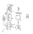
- Figure 1 schematically illustrates a conventional gas turbine system.
- the system includes a gas turbine 100 having, inter alia, a plurality of combustion chambers 101, a plurality of pressure transducers 103a, 103b installed in respective combustion chambers 101 for measuring pressure therein, an emission sensor 107 installed in each of the combustion chambers 101 for measuring emissions therein, and a fuel manifold (not shown) for controlling and providing fuel splits to the turbine 100.
- a tuning kit 130 including a signal conditioner 133 and a dynamics monitor 135 is operatively coupled to the gas turbine 100.
- the signal conditioner 133 is connected through a coaxial cable 131 to the pressure transducers 103a, 103b for receiving raw data signals from the pressure transducers 103a, 103b.
- the signal conditioner 133 processes the received raw data signals by providing an analog to digital conversion to the raw data and outputs corresponding signals to the combustion dynamics monitor 135.
- the combustion dynamics monitor 135 includes a computer that provides further signal processing to the received signals and ultimately generates a fast fourier transform (FFT) from which maximum amplitudes and frequencies of the combustion dynamics of the turbine 100 can be determined.
- FFT fast fourier transform
- An emissions system 104 is connected to the emissions sensors 107 (one shown) to provide data regarding the amount of substances such as NO X and CO in the exhaust of the turbine 100.
- An on-site engineer can analyze the amplitude and frequency data generated by the combustion dynamics monitor 135 and/or emissions system 104 and determine any necessary adjustments to the gas turbine 100 such as an adjustment to the fuel split settings.
- a turbine controller 110 such as a Mark V turbine controller is operatively connected to the turbine 100.
- a processor such as an "I" processor 140 is connected to the turbine controller 110 for exchanging data using Arcnet protocol. Alter the engineer determines the necessary changes to the gas turbine 100, the engineer can provide an input Into the processor 140 such as new fuel split control values to implement the changes. The processor 140 provides the control values to the turbine controller 110 which, in turn, provides a corresponding signal to the turbine 100 so that the turbine 100 can be tuned to the new settings reflecting the input into the processor 140.
- the engineer will make another set of measurements through the pressure transducers 103a, 103b and/or emissions sensors 107 to thus obtain another measurement of the combustion dynamics and/or emissions of the turbine 100. This process is repeated until a map of combustion dynamics and/or emissions as a function of fuel splits and operating mode is developed. Using this map, the engineer can determine the optimum fuel split settings to achieve low emissions and low dynamics.
- the conventional gas turbines require tuning to minimize combustion dynamics and emissions. This tuning is performed locally. The engineer must therefore be present on-site at the location of the turbine to tune the turbine. Soften, the engineer must wait around for other subsystems to become ready to tune the turbine.
- EP-A-1 168 121 discloses a remote monitoring system that has a central computer system and at least one data acquisition unit for collecting data from a machine to be monitored.
- the data acquisition unit includes an on-site computer system having a central processor and an auxiliary processor.
- the data acquisition unit further includes one or more sensors for generating a process data signal and one or more sensors for generating a dynamic data signal.
- the process data signal is fed to the central processor and the auxiliary processor, and the dynamic data signal is fed to the auxiliary processor.
- a communication link connects the central computer system and the on-site computer system.
- a system for tuning turbine comprises a turbine controller operatively coupled to the turbine, a first computer system operatively coupled to the turbine controller and located locally to the turbine, and a second computer system for exchanging data with the first computer system that is located remotely from the turbine.
- the first computer system and the second computer system exchange data over a network connection such as an intranet, the internet or a virtual private network.
- the first computer system comprises an on-site monitor and the second computer system comprises a local area network having a workstation, and the first computer system is capable of exchanging data with the workstation via the on-site monitor.
- the on-site monitor exchanges data with the turbine controller using a first protocol and exchanges data with the second computer system using a second protocol different than the first protocol.
- the first computer system is capable of transmitting data relating to a characteristic of the turbine to the second computer system such as combustion dynamics and/or emissions of the turbine.
- the second computer system is capable of receiving input from a system user and transmitting control data relating to turbine fuel splits and reflecting the input from the system user to the first computer system.
- the first computer system is capable of providing the control data to the turbine controller to tune the turbine in accordance with control data.
- a method of tuning a turbine comprises providing a turbine controller that is operatively coupled to the turbine, operatively coupling a first computer system to the turbine controller and locating the first computer system locally to the turbine, and exchanging data between the first computer system and a second computer system that is located remotely from the turbine to enable the turbine to be tuned.
- the data exchange between the first computer system and the second computer system is accomplished over a network connection such as an intranet, the internet or a virtual private network.
- the first computer system exchanges data with the turbine controller using a first protocol and exchanges data with the second computer system using a second protocol different than the first protocol.
- the method further comprises transmitting data relating to a characteristic of the turbine such as combustion dynamics and/or emissions from the first computer system to the second computer system.
- the method further comprises transmitting control data from the second computer system to the first computer system, the control data reflecting input to the second computer system from a system user, and providing the control data received by the first computer system to the turbine controller to tune the turbine in accordance with the control data.
- the control data relates to setting fuel splits of the turbine.
- the present invention provides a significant improvement in productivity. For example, the same engineer could tune differently located turbines from a single point in an automated fashion and the frequency of tunings can be increased. Furthermore, long term monitoring of a turbine can be enhanced.
- a system comprises a first turbine, a first turbine controller operatively coupled to the first turbine for transmitting data relating to a characteristic such as combustion dynamics and/or emissions of the first turbine to a remote location over a network connection.
- the system further comprises a second computer system located at the remote location from the turbine for receiving data transmitted from the first computer system over the network connection.
- the network connection comprises an intranet, the internet or a virtual private network.
- the system further comprises a second turbine and a second turbine controller operatively coupled to the second turbine and to the first computer system.
- a method of tuning a turbine comprises providing a first turbine, operatively coupling a first turbine controller to the first turbine, transmitting data relating to a characteristic such as combustion dynamics and/or emissions of the first turbine to a location remote from the first turbine over a network connection.
- the network connection comprises an intranet, the internet or a virtual private network.
- the first turbine specifically transmits the data to a second computer system located remotely from the turbine so that an evaluation of the transmitted data can be made and any necessary changes to the turbine can be communicated (e.g., by telephone) to a person on-site of the turbine.
- the method further comprises providing a second turbine, operatively coupling a second turbine controller to the second turbine, transmitting data relating to a characteristic of the second turbine to the location remote from the first turbine over the network connection, the location remote from the first turbine also being remote from the second turbine.
- Multiple turbines at one location can therefore be controlled by a remote engineer.
- a system comprises a first turbine, a first turbine controller operatively coupled to the first turbine, a first computer system operatively coupled to the first turbine controller and located locally to the first turbine, a second turbine, a second turbine controller operatively coupled to the second turbine, a second computer system operatively coupled to the second turbine controller and located locally to the second turbine, and a third computer system for exchanging data with the first computer system and the second computer system.
- the third computer system is located remotely from the first and second turbines and the first and second turbines are located remotely from each other.
- the third computer system exchanges data with the first computer system and the second computer system via a network connection such as an intranet, an internet or a virtual private network.
- the first computer system is capable of transmitting data relating to combustion dynamics and/or emissions of the first turbine to the third computer system and the second computer system is capable of transmitting data relating to combustion dynamics and/or emissions of the second turbine to the third computer system.
- the third computer system is capable of receiving the inputs from a system user and transmitting control data to the first computer system and the second computer system reflecting the inputs from the system user.
- the first computer system is capable of providing control data to the first turbine controller to tune the first turbine accordingly
- the second computer system is capable of providing control data to the second turbine controller to tune the second turbine accordingly.
- the control data transmitted from the third computer system to the first computer system relates to setting fuel splits of the first turbine and the control data transmitted from the third computer system to the second computer system relates to setting fuel splits of the second turbine.
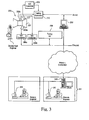
- FIG. 2 illustrates an exemplary embodiment of a remotely tuned gas turbine system in accordance with the present invention.
- the system includes a gas turbine 200 having a plurality of combustion chambers 201, pressure transducers 203a, 203b respectively installed in the combustion chambers 201, an emissions sensor 207 installed in each of the combustion chambers 201 and a fuel manifold (not shown).
- the pressure transducers 203a, 203b measure the pressure within each of combustion chambers of the turbine 200 and thus provide a measure of the combustion dynamics of the turbine 200.
- the emission sensors 207 (one shown) measure the amount of substances such as NO X and CO in the exhaust of the combustion chambers 201 of the gas turbine 200.
- the fuel manifold enables the distribution of the fuel provided to be turbine 200 to be split in a controlled manner.
- the system further includes analog to digital A/D converters 205a, 205b, 209, a tuning kit 230, an on-site monitor (OSM) 250, and a turbine controller 210.
- the A/D converters 205a, 205b, 209, the tuning kit 230, the OSM 250 and the turbine controller 210 effectively form a computer system that is located locally to the turbine 200.
- the A/D converters 205a, 205b, the tuning kit 230 and the OSM 250 operatively communicate (i.e., exchange data) with each other using a shared protocol such as Ethernet.
- the OSM 250 and the turbine controller 210 communicate with each other using the same or a different protocol such as Arcnet.
- the A/D converters 205a and 205b are connected to the pressure transducers 203a and 203b, respectively, to receive the analog signals reflecting the raw data measurements of the pressure transducers 203a, 203b and to convert the analog signals into digital data.
- the tuning kit 230 runs a computer program that collects the digital data from the A/D converters 205a, 205b. The program run by the tuning kit 230 also performs signal processing on the digital data and generates a FFT having amplitude and frequency data from which maximum amplitudes and frequencies of combustion dynamics can be determined.
- A/D converters 209 are connected to emissions sensors 207, respectively, to receive the analog signals reflecting the raw data measurements of the emissions sensors 207 and to convert the analog signals into digital data.
- the digital data from the A/D converters 209 is provided to the turbine controller 210.
- the turbine controller 210 forwards corresponding data relating to the measurements by the emissions sensors 207 to the OSM 250 using Arcnet protocol.
- the remotely tuned turbine system also includes a local area network (LAN) 240.
- the LAN 240 is remotely located from the gas turbine 200.
- the gas turbine 200 and the LAN 240 can be located in different cities.
- the LAN 240 comprises a server 245 that is operatively connected to a plurality of workstations 241, 243 which also may be located remotely from each other such as in different cities.
- the LAN 240 is capable of communicating with the OSM 250 over a network connection such as the internet, an intranet or a virtual private network (VPN).
- data can be exchanged with the locally located OSM 250 and the remotely located server 245 of the LAN 240.
- the server 245 in turn exchanges data with at least one of the workstations 241, 243.
- the OSM 250 thus serves as a hub that allows the remotely located workstations 241, 243 to communicate with the computer system that is locally located to the turbine 200 through the server 245 and the network connection.
- the tuning kit 230 After the tuning kit 230 has generated the frequency and amplitude data, the tuning kit 230 provides this processed data to the OSM 250 using an ethernet protocol. The OSM 250 then transmits the data over the network connection to the server 245. Additionally (or in the alternative), data relating to the measurements of the emission sensors 207 is provided from the turbine controller 210 to the OSM 250 using an Arcnet protocol. The OSM 250 then transmits the data over the network connection to the server 245 using an Ethernet protocol. The server 245 provides this data it has received to one or more of the workstations 241, 243 so that a system user (e.g., an engineer at workstation 241 or 243 as illustrated in Fig. 2 ) can interpret the data. The user can determine whether any necessary changes, such as adjustments to the fuel splits provided by the fuel manifold of the turbine system, that need to be made to the turbine to improve its performance.
- a system user e.g., an engineer at workstation 241 or 243 as illustrated in Fig. 2
- the system user can input these changes into one of the workstations 241, 243.
- Control data reflecting these changes such as fuel split control data, is transmitted from one of the workstations 241 or 243 by a computer program running on the workstations 241, 243 to the server 245. This data is then transmitted over the network connection to the OSM 250.
- the input provided into one of the workstations 241 or 243 is displayed on the other workstations 243 or 241 of the LAN 240 so that other system users can be informed of the input.
- the OSM 250 runs a program that sends the control data to the turbine controller 210 using Arcnet protocol.
- the program run by the OSM 250 also ensures the remote workstations 241, 243 are operatively connected thereto.
- the turbine controller 210 preferably a Mark V turbine controller, is connected to and exchanges data with the turbine 200. After the turbine controller 210 receives the control data from the OSM 250, it sends corresponding signals to the turbine 200 to tune the settings of the turbine. For example, the turbine controller 210 can transmit and signals reflecting new fuel split settings in accordance with the input provided by the system user at one of the remote workstations 241, 243. An engineer located on-site of the turbine 200 can verify proper operation of the turbine system.
- another set of pressure measurements and/or emissions measurements can be made by the pressure transducer 203a, 203b and/or emissions sensor 207 to determine the combustion dynamics and/or emissions of the turbine 200.
- the data relating to these measurements can be transmitted by the OSM 250 over the network connection to the remotely located LAN 240. Further evaluation of the results by the system user and subsequent tuning of the turbine as discussed above is repeated until a map of combustion dynamics and/or emissions as a function of fuel splits is developed. From this map, the optimum fuel split settings can be determined so that the lowest emissions and lowest combustion dynamics can be attained.
- the present invention thus enables a remotely located system user to tune a turbine. Significant improvements in the user's productivity can be obtained, for example, by eliminating the need for the user to travel to the turbine site.
- Figure 3 illustrates another exemplary embodiment of a gas turbine system that is operatively connected to a remotely located LAN 240.
- reference numbers corresponding to parts described in previous embodiments shall remain the same. Only the differences from the previous embodiment(s) shall be discussed in detail.
- data relating to combustion dynamics and/or emissions of the gas turbine 200 are transmitted over the network connection to the LAN 240 as discussed above.
- a system user e.g., a remotely located engineer
- the system user will communicate, preferably by telephone, any necessary changes to an engineer who is located on-site of the gas turbine 200.
- these changes can include, for example, adjustments to the fuel split settings of the turbine 200.
- the on-site engineer will locally perform any necessary tuning in accordance with the instructions communicated by the remote system user. There is thus no need to transmit control data relating to any necessary changes to the turbine over the network connection from the LAN 240 to the OSM 250.
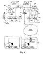
- Figure 4 illustrates a gas turbine system having multiple (e.g., two) turbines connected to a computer network that is located locally to the turbines according to another exemplary embodiment of the present invention.
- the turbine system illustrated in Figure 4 includes all of the components of the turbine system illustrated in Figure 2 .
- the gas turbine system further includes a second gas turbine 200a having a plurality of combustion chambers 201 a, a plurality of pressure transducers 203c, 203d respectively installed in the combustion chambers 201a, emissions sensors 207a (one shown) respectfully installed in the combustion chambers 201 a and a fuel manifold (not shown).
- the pressure transducers 203c, 203d are respectively connected to A/D converters 205c, 205d.
- A/D converters 209a (one shown) are respectively connected to the emissions sensors 207a.
- the output of the A/D converters 209a are provided to turbine controller 210a which exchanges data with OSM 250 using an Arcnet protocol.
- gas turbine 200a and its operatively connected components are similar to gas turbine 200 and its corresponding operatively connected components. As illustrated in Figure 4 , both of the turbines 200, 200a are operatively connected to the same tuning kit 230 and OSM 250. The OSM can thus exchange data with the LAN 240 over the network connection to tune both turbines 200, 200a.
- the turbine 200 and 200a are located locally to each other and are located remotely from the LAN 240.
- the system disclosed in Figure 4 can be modified in accordance with the embodiment of Figure 3 . That is, the system illustrated in Figure 4 can be modified so that a system user at one of the remote workstations 241 or 243 can evaluate data received over the network connection from the turbines 200, 200a and communicate instructions to (e.g., by telephone) an on-site engineer to perform local tuning of the turbines 200, 200a.
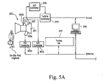
- FIGS 5A-5B illustrate multiple gas turbine systems that are each operatively connected to the LAN 240 in accordance with another exemplary embodiment of the present invention.
- the turbine systems are located remotely from each other and are both located remotely from the LAN 240.
- each of the gas turbine systems and the LAN 240 can be located in different cities.
- the first turbine system includes turbine 200 and all of the other components discussed in the embodiment of Figure 2 .
- the second gas turbine system includes a gas turbine 300 having a plurality of combustion chambers 301, a plurality of pressure transducers 303a, 303b respectively installed in the combustion chambers 301, emissions sensors 307 (one shown) respectively installed in the combustion chambers 301 and a fuel manifold (not shown).
- the second gas turbine system further includes A/D converters 305a, 305b, 309, a tuning kit 330, an OSM 350 and a turbine controller. 310.
- the pressure transducers 303a, 303b and emissions sensors 307 measure the pressure and emissions of the turbine 301, respectively, in a manner similar to pressure transducers 203a, 203b and emission sensors 207.
- the raw data from the measurements of the pressure transducers 303a, 303b and emissions sensors 307 are processed and output by the A/D converters 305a, 305b, 309 to the tuning kit 330 and the turbine controller 310 and later transmitted by OSM 350 in a manner similar to corresponding parts (A/D converters 205a, 205b, 209, turbine controller 210, tuning kit 230 and OSM 250) of the first turbine system.
- the OSMs 250, 350 are both capable of exchanging data with LAN 240 over the network connection to tune turbine 200, 300, respectively.
- the system user at one of the workstations 241, 243 can thus tune each of the turbines 200, 300 from a single location remote from both of the turbines 200, 300.
- the engineer thus does not need to unnecessarily travel between the locations of the turbines 200, 300 and therefore can tune turbines 200, 300 with enhanced efficiency.
- FIG. 5 The embodiment disclosed in Figure 5 can be modified in accordance with the embodiment of Figure 3 . That is, after the system user at one of the workstations 241, 243 evaluates data that has been transmitted over the network connection relating to the measurements performed at the turbines 200, 300, the system user can communicate any necessary changes, (e.g., by telephone) to respective on-site engineers at the locations of the turbines 200, 300 for local tuning. Thus, no control data needs to be transmitted back from the LAN 240 to the OSMs 250, 350 over the network connection to tune turbines 200, 300.
- any necessary changes e.g., by telephone
Landscapes
- Engineering & Computer Science (AREA)
- Physics & Mathematics (AREA)
- Combustion & Propulsion (AREA)
- Chemical & Material Sciences (AREA)
- General Physics & Mathematics (AREA)
- General Engineering & Computer Science (AREA)
- Automation & Control Theory (AREA)
- Health & Medical Sciences (AREA)
- Software Systems (AREA)
- Evolutionary Computation (AREA)
- Mechanical Engineering (AREA)
- Business, Economics & Management (AREA)
- Medical Informatics (AREA)
- Artificial Intelligence (AREA)
- Computer Vision & Pattern Recognition (AREA)
- Tourism & Hospitality (AREA)
- Theoretical Computer Science (AREA)
- Strategic Management (AREA)
- Marketing (AREA)
- Human Resources & Organizations (AREA)
- General Health & Medical Sciences (AREA)
- Economics (AREA)
- Primary Health Care (AREA)
- General Business, Economics & Management (AREA)
- Selective Calling Equipment (AREA)
- Engine Equipment That Uses Special Cycles (AREA)
- Combined Controls Of Internal Combustion Engines (AREA)
Description
- The present invention relates to a system and method for tuning two remotely located gas turbines, and in particular, to a system and method for tuning two remotely located gas turbines from a remote computer.
-
Figure 1 schematically illustrates a conventional gas turbine system. The system includes agas turbine 100 having, inter alia, a plurality ofcombustion chambers 101, a plurality ofpressure transducers respective combustion chambers 101 for measuring pressure therein, anemission sensor 107 installed in each of thecombustion chambers 101 for measuring emissions therein, and a fuel manifold (not shown) for controlling and providing fuel splits to theturbine 100. - A
tuning kit 130 including asignal conditioner 133 and adynamics monitor 135 is operatively coupled to thegas turbine 100. Specifically, thesignal conditioner 133 is connected through acoaxial cable 131 to thepressure transducers pressure transducers signal conditioner 133 processes the received raw data signals by providing an analog to digital conversion to the raw data and outputs corresponding signals to the combustion dynamics monitor 135. Thecombustion dynamics monitor 135 includes a computer that provides further signal processing to the received signals and ultimately generates a fast fourier transform (FFT) from which maximum amplitudes and frequencies of the combustion dynamics of theturbine 100 can be determined. - An
emissions system 104 is connected to the emissions sensors 107 (one shown) to provide data regarding the amount of substances such as NOX and CO in the exhaust of theturbine 100. An on-site engineer can analyze the amplitude and frequency data generated by thecombustion dynamics monitor 135 and/oremissions system 104 and determine any necessary adjustments to thegas turbine 100 such as an adjustment to the fuel split settings. - A
turbine controller 110 such as a Mark V turbine controller is operatively connected to theturbine 100. A processor such as an "I"processor 140 is connected to theturbine controller 110 for exchanging data using Arcnet protocol. Alter the engineer determines the necessary changes to thegas turbine 100, the engineer can provide an input Into theprocessor 140 such as new fuel split control values to implement the changes. Theprocessor 140 provides the control values to theturbine controller 110 which, in turn, provides a corresponding signal to theturbine 100 so that theturbine 100 can be tuned to the new settings reflecting the input into theprocessor 140. - After the
gas turbine 100 has adjusted to the new settings, the engineer will make another set of measurements through thepressure transducers emissions sensors 107 to thus obtain another measurement of the combustion dynamics and/or emissions of theturbine 100. This process is repeated until a map of combustion dynamics and/or emissions as a function of fuel splits and operating mode is developed. Using this map, the engineer can determine the optimum fuel split settings to achieve low emissions and low dynamics. - The conventional gas turbines require tuning to minimize combustion dynamics and emissions. This tuning is performed locally. The engineer must therefore be present on-site at the location of the turbine to tune the turbine. Soften, the engineer must wait around for other subsystems to become ready to tune the turbine.
-
EP-A-1 168 121 discloses a remote monitoring system that has a central computer system and at least one data acquisition unit for collecting data from a machine to be monitored. The data acquisition unit includes an on-site computer system having a central processor and an auxiliary processor. The data acquisition unit further includes one or more sensors for generating a process data signal and one or more sensors for generating a dynamic data signal. The process data signal is fed to the central processor and the auxiliary processor, and the dynamic data signal is fed to the auxiliary processor. A communication link connects the central computer system and the on-site computer system. - See as well
US 5 606 627 A . - It would thus be beneficial to enable the engineer to tune turbines from a remote location, thereby resulting in improved productivity.
- In an example, a system for tuning turbine comprises a turbine controller operatively coupled to the turbine, a first computer system operatively coupled to the turbine controller and located locally to the turbine, and a second computer system for exchanging data with the first computer system that is located remotely from the turbine. The first
computer system and the second computer system exchange data over a network connection such as an intranet, the internet or a virtual private network. The first computer system comprises an on-site monitor and the second computer system comprises a local area network having a workstation, and the first computer system is capable of exchanging data with the workstation via the on-site monitor. The on-site monitor exchanges data with the turbine controller using a first protocol and exchanges data with the second computer system using a second protocol different than the first protocol. The first computer system is capable of transmitting data relating to a characteristic of the turbine to the second computer system such as combustion dynamics and/or emissions of the turbine. The second computer system is capable of receiving input from a system user and transmitting control data relating to turbine fuel splits and reflecting the input from the system user to the first computer system. The first computer system is capable of providing the control data to the turbine controller to tune the turbine in accordance with control data. - In another example, a method of tuning a turbine comprises providing a turbine controller that is operatively coupled to the turbine, operatively coupling a first computer system to the turbine controller and locating the first computer system locally to the turbine, and exchanging data between the first computer system and a second computer system that is located remotely from the turbine to enable the turbine to be tuned. The data exchange between the first computer system and the second computer system is accomplished over a network connection such as an intranet, the internet or a virtual private network. The first computer system exchanges data with the turbine controller using a first protocol and exchanges data with the second computer system using a second protocol different than the first protocol. The method further comprises transmitting data relating to a characteristic of the turbine such as combustion dynamics and/or emissions from the first computer system to the second computer system. The method further comprises transmitting control data from the second computer system to the first computer system, the control data reflecting input to the second computer system from a system user, and providing the control data received by the first computer system to the turbine controller to tune the turbine in accordance with the control data. In an exemplary embodiment, the control data relates to setting fuel splits of the turbine.
- By enabling the engineer to tune the turbine from a remote location, the present invention provides a significant improvement in productivity. For example, the same engineer could tune differently located turbines from a single point in an automated fashion and the frequency of tunings can be increased. Furthermore, long term monitoring of a turbine can be enhanced.
- In an exemplary embodiment of the invention, a system comprises a first turbine, a first turbine controller operatively coupled to the first turbine for transmitting data relating to a characteristic such as combustion dynamics and/or emissions of the first turbine to a remote location over a network connection. The system further comprises a second computer system located at the remote location from the turbine for receiving data transmitted from the first computer system over the network connection. The network connection comprises an intranet, the internet or a virtual private network. The system further comprises a second turbine and a second turbine controller operatively coupled to the second turbine and to the first computer system.
- In yet another exemplary embodiment of the invention, a method of tuning a turbine comprises providing a first turbine, operatively coupling a first turbine controller to the first turbine, transmitting data relating to a characteristic such as combustion dynamics and/or emissions of the first turbine to a location remote from the first turbine over a network connection. The network connection comprises an intranet, the internet or a virtual private network. The first turbine specifically transmits the data to a second computer system located remotely from the turbine so that an evaluation of the transmitted data can be made and any necessary changes to the turbine can be communicated (e.g., by telephone) to a person on-site of the turbine. The method further comprises providing a second turbine, operatively coupling a second turbine controller to the second turbine, transmitting data relating to a characteristic of the second turbine to the location remote from the first turbine over the network connection, the location remote from the first turbine also being remote from the second turbine. Multiple turbines at one location can therefore be controlled by a remote engineer.
- In yet another exemplary embodiment of the present invention, a system comprises a first turbine, a first turbine controller operatively coupled to the first turbine, a first computer system operatively coupled to the first turbine controller and located locally to the first turbine, a second turbine, a second turbine controller operatively coupled to the second turbine, a second computer system operatively coupled to the second turbine controller and located locally to the second turbine, and a third computer system for exchanging data with the first computer system and the second computer system. The third computer system is located remotely from the first and second turbines and the first and second turbines are located remotely from each other. The third computer system exchanges data with the first computer system and the second computer system via a network connection such as an intranet, an internet or a virtual private network. The first computer system is capable of transmitting data relating to combustion dynamics and/or emissions of the first turbine to the third computer system and the second computer system is capable of transmitting data relating to combustion dynamics and/or emissions of the second turbine to the third computer system. The third computer system is capable of receiving the inputs from a system user and transmitting control data to the first computer system and the second computer system reflecting the inputs from the system user. The first computer system is capable of providing control data to the first turbine controller to tune the first turbine accordingly, and the second computer system is capable of providing control data to the second turbine controller to tune the second turbine accordingly. The control data transmitted from the third computer system to the first computer system relates to setting fuel splits of the first turbine and the control data transmitted from the third computer system to the second computer system relates to setting fuel splits of the second turbine.
- These, as well as other advantages of this invention, will be more completely understood and appreciated by careful study of the following more detailed description of the presently preferred exemplary embodiments of the invention taken in conjunction with the accompanying drawings, in which:
-
FIGURE 1 is a schematic diagram illustrating a conventional gas turbine system; -
FIGURE 2 is a schematic diagram illustrating a gas turbine system that is operatively connected to and exchanges data with a remote computer system according to an exemplary embodiment of the present invention; -
FIGURE 3 is a schematic diagram illustrating a gas turbine system that is operatively connected with and transmits data to a remote computer system according to another exemplary embodiment of the present invention; -
FIGURE 4 is a schematic diagram illustrating a gas turbine system having multiple turbines operatively coupled to a local computer system that is operatively connected to a remote computer system according to another exemplary embodiment of the present invention. -
FIGURES 5A and5B form a schematic diagram illustrating multiple gas turbine systems that are remote from each other and are operatively connected to a remote computer system according to another exemplary embodiment of the present invention. -
Figure 2 illustrates an exemplary embodiment of a remotely tuned gas turbine system in accordance with the present invention. The system includes agas turbine 200 having a plurality ofcombustion chambers 201,pressure transducers combustion chambers 201, anemissions sensor 207 installed in each of thecombustion chambers 201 and a fuel manifold (not shown). Thepressure transducers turbine 200 and thus provide a measure of the combustion dynamics of theturbine 200. The emission sensors 207 (one shown) measure the amount of substances such as NOX and CO in the exhaust of thecombustion chambers 201 of thegas turbine 200. The fuel manifold enables the distribution of the fuel provided to beturbine 200 to be split in a controlled manner. - The system further includes analog to digital A/
D converters tuning kit 230, an on-site monitor (OSM) 250, and aturbine controller 210. The A/D converters tuning kit 230, theOSM 250 and theturbine controller 210 effectively form a computer system that is located locally to theturbine 200. The A/D converters tuning kit 230 and theOSM 250 operatively communicate (i.e., exchange data) with each other using a shared protocol such as Ethernet. TheOSM 250 and theturbine controller 210 communicate with each other using the same or a different protocol such as Arcnet. - The A/
D converters pressure transducers pressure transducers tuning kit 230 runs a computer program that collects the digital data from the A/D converters tuning kit 230 also performs signal processing on the digital data and generates a FFT having amplitude and frequency data from which maximum amplitudes and frequencies of combustion dynamics can be determined. - A/D converters 209 (one shown) are connected to
emissions sensors 207, respectively, to receive the analog signals reflecting the raw data measurements of theemissions sensors 207 and to convert the analog signals into digital data. The digital data from the A/D converters 209 is provided to theturbine controller 210. Theturbine controller 210 forwards corresponding data relating to the measurements by theemissions sensors 207 to theOSM 250 using Arcnet protocol. - The remotely tuned turbine system also includes a local area network (LAN) 240. The
LAN 240 is remotely located from thegas turbine 200. For example, thegas turbine 200 and theLAN 240 can be located in different cities. TheLAN 240 comprises aserver 245 that is operatively connected to a plurality ofworkstations LAN 240 is capable of communicating with theOSM 250 over a network connection such as the internet, an intranet or a virtual private network (VPN). Specifically, data can be exchanged with the locally locatedOSM 250 and the remotely locatedserver 245 of theLAN 240. Theserver 245 in turn exchanges data with at least one of theworkstations OSM 250 thus serves as a hub that allows the remotely locatedworkstations turbine 200 through theserver 245 and the network connection. - After the
tuning kit 230 has generated the frequency and amplitude data, thetuning kit 230 provides this processed data to theOSM 250 using an ethernet protocol. TheOSM 250 then transmits the data over the network connection to theserver 245. Additionally (or in the alternative), data relating to the measurements of theemission sensors 207 is provided from theturbine controller 210 to theOSM 250 using an Arcnet protocol. TheOSM 250 then transmits the data over the network connection to theserver 245 using an Ethernet protocol. Theserver 245 provides this data it has received to one or more of theworkstations workstation Fig. 2 ) can interpret the data. The user can determine whether any necessary changes, such as adjustments to the fuel splits provided by the fuel manifold of the turbine system, that need to be made to the turbine to improve its performance. - If the system user determines that changes need to be made to the
turbine 200, the system user can input these changes into one of theworkstations workstations workstations server 245. This data is then transmitted over the network connection to theOSM 250. The input provided into one of theworkstations other workstations LAN 240 so that other system users can be informed of the input. - The
OSM 250 runs a program that sends the control data to theturbine controller 210 using Arcnet protocol. The program run by theOSM 250 also ensures theremote workstations turbine controller 210, preferably a Mark V turbine controller, is connected to and exchanges data with theturbine 200. After theturbine controller 210 receives the control data from theOSM 250, it sends corresponding signals to theturbine 200 to tune the settings of the turbine. For example, theturbine controller 210 can transmit and signals reflecting new fuel split settings in accordance with the input provided by the system user at one of theremote workstations turbine 200 can verify proper operation of the turbine system. - After the
turbine 200 adjusts to the new settings dictated by theturbine controller 210, another set of pressure measurements and/or emissions measurements can be made by thepressure transducer emissions sensor 207 to determine the combustion dynamics and/or emissions of theturbine 200. In the same manner discussed above, the data relating to these measurements can be transmitted by theOSM 250 over the network connection to the remotely locatedLAN 240. Further evaluation of the results by the system user and subsequent tuning of the turbine as discussed above is repeated until a map of combustion dynamics and/or emissions as a function of fuel splits is developed. From this map, the optimum fuel split settings can be determined so that the lowest emissions and lowest combustion dynamics can be attained. - The present invention thus enables a remotely located system user to tune a turbine. Significant improvements in the user's productivity can be obtained, for example, by eliminating the need for the user to travel to the turbine site.
-
Figure 3 illustrates another exemplary embodiment of a gas turbine system that is operatively connected to a remotely locatedLAN 240. In this and all following embodiments, reference numbers corresponding to parts described in previous embodiments shall remain the same. Only the differences from the previous embodiment(s) shall be discussed in detail. - In the exemplary embodiment illustrated in
Figure 3 , data relating to combustion dynamics and/or emissions of thegas turbine 200 are transmitted over the network connection to theLAN 240 as discussed above. However, after a system user (e.g., a remotely located engineer) has evaluated the data transmitted to theLAN 240 at one of theworkstations gas turbine 200. As discussed above, these changes can include, for example, adjustments to the fuel split settings of theturbine 200. The on-site engineer will locally perform any necessary tuning in accordance with the instructions communicated by the remote system user. There is thus no need to transmit control data relating to any necessary changes to the turbine over the network connection from theLAN 240 to theOSM 250. -
Figure 4 illustrates a gas turbine system having multiple (e.g., two) turbines connected to a computer network that is located locally to the turbines according to another exemplary embodiment of the present invention. Specifically, the turbine system illustrated inFigure 4 includes all of the components of the turbine system illustrated inFigure 2 . However, the gas turbine system further includes asecond gas turbine 200a having a plurality ofcombustion chambers 201 a, a plurality ofpressure transducers combustion chambers 201a,emissions sensors 207a (one shown) respectfully installed in thecombustion chambers 201 a and a fuel manifold (not shown). Thepressure transducers D converters D converters 209a (one shown) are respectively connected to theemissions sensors 207a. The output of the A/D converters 209a are provided toturbine controller 210a which exchanges data withOSM 250 using an Arcnet protocol. - The structure and operation of
gas turbine 200a and its operatively connected components are similar togas turbine 200 and its corresponding operatively connected components. As illustrated inFigure 4 , both of theturbines same tuning kit 230 andOSM 250. The OSM can thus exchange data with theLAN 240 over the network connection to tune bothturbines turbine LAN 240. - As will be appreciated by those skilled in the art, the system disclosed in
Figure 4 can be modified in accordance with the embodiment ofFigure 3 . That is, the system illustrated inFigure 4 can be modified so that a system user at one of theremote workstations turbines turbines -
Figures 5A-5B illustrate multiple gas turbine systems that are each operatively connected to theLAN 240 in accordance with another exemplary embodiment of the present invention. The turbine systems are located remotely from each other and are both located remotely from theLAN 240. For example, each of the gas turbine systems and theLAN 240 can be located in different cities. - The first turbine system includes
turbine 200 and all of the other components discussed in the embodiment ofFigure 2 . The second gas turbine system includes agas turbine 300 having a plurality ofcombustion chambers 301, a plurality ofpressure transducers combustion chambers 301, emissions sensors 307 (one shown) respectively installed in thecombustion chambers 301 and a fuel manifold (not shown). The second gas turbine system further includes A/D converters tuning kit 330, anOSM 350 and a turbine controller. 310. Thepressure transducers emissions sensors 307 measure the pressure and emissions of theturbine 301, respectively, in a manner similar topressure transducers emission sensors 207. The raw data from the measurements of thepressure transducers emissions sensors 307 are processed and output by the A/D converters tuning kit 330 and theturbine controller 310 and later transmitted byOSM 350 in a manner similar to corresponding parts (A/D converters turbine controller 210,tuning kit 230 and OSM 250) of the first turbine system. Accordingly, theOSMs LAN 240 over the network connection to tuneturbine workstations turbines turbines turbines turbines - The embodiment disclosed in
Figure 5 can be modified in accordance with the embodiment ofFigure 3 . That is, after the system user at one of theworkstations turbines turbines LAN 240 to theOSMs turbines
Claims (2)
- A system for tuning a gas turbine (200), comprising:a first gas turbine (200);a second gas turbine (300);a first turbine controller (210) operatively coupled to the first gas turbine (200);a second turbine controller (310) operatively coupled to the second gas turbine (300);a first computer system operatively coupled to the first turbine controller (210);a second computer system operatively coupled to the second turbine controller (310);a third computer system (240) for exchanging data with the first and second computer systems, the third computer system (240) being located remotely from the first and second turbines (200, 300); and characterized in thatthe first computer system being adapted for transmitting data relating to combustion dynamics and/or emissions of the first gas turbine (200) to the third computer system (240) over the network connection, and for processing control data received over the network connection in response to the transmitted data relating to the combustion dynamics and/or emissions of the first gas turbine (200) to enable the first turbine controller (210) to tune fuel split settings of the first gas turbine (200);the second computer system being adapted for transmitting data relating to combustion dynamics and/or emissions of the second gas turbine (200) to the third computer system (240) over the network connection, and for processing control data received over the network connection in response to the transmitted data relating to the combustion dynamics and/or emissions of the second gas turbine (300) to enable the second turbine controller (310) to tune fuel split settings of the second gas turbine (200).the third computer system arranged to receive user input in response to the data transmitted from the first and second computer systems and to transmit the control data reflecting the received user input to the first and second computer systems; whereinthe first and second gas turbines (200, 300) are located remotely from each other; andthe network connection is an internet, intranet or virtual private network.
- A method of tuning at least one gas turbine (200) comprising:providing a first gas turbine (200);providing a second gas turbine (300);operatively coupling a first turbine controller (210) to the first gas turbine (200);operatively coupling a second turbine controller (310) to the second gas turbine (300);providing a first computer system operatively coupled to the first turbine controller (210);providing a second computer system operatively coupled to the second turbine controller (310);providing a third computer system (240) for exchanging data with the first and second computer systems, the third computer system (240) being located remotely from the first and second turbines (200, 300);transmitting data to the third computer system (240) from the first and second turbines (200, 300) over a network connection; characterised in thatthe first computer system operatively coupled to the first turbine controller (210) transmitting data relating to combustion dynamics and/or emissions of the first gas turbine (200) to the location remote from the first turbine (200) over the network connection, and processing control data received over the network connection in response to the transmitted data relating to the combustion dynamics and/or emissions of the first gas turbine (200) to enable the first turbine controller (210) to tune fuel split settings of the first gas turbine (200);the second computer system operatively coupled to the second turbine controller (310) transmitting data relating to combustion dynamics and/or emissions of the second gas turbine (300) to the location remote from the second turbine (300) over the network connection, and processing control data received over the network connection in response to the transmitted data relating to the combustion dynamics and/or emissions of the second gas turbine (300) to enable the second turbine controller (310) to tune fuel split settings of the second gas turbine (300);the third computer system (240) located remotely from the turbines (200,300) receiving user input in response to the data transmitted from the first and second computer systems and transmitting the control data reflecting the received user input to the first and second computer systems; andthe network connection is an internet, intranet or virtual private network.
Priority Applications (1)
| Application Number | Priority Date | Filing Date | Title |
|---|---|---|---|
| EP10183254.1A EP2282032A3 (en) | 2001-07-17 | 2002-07-11 | Remote tuning for gas turbines |
Applications Claiming Priority (2)
| Application Number | Priority Date | Filing Date | Title |
|---|---|---|---|
| US906001 | 1992-06-26 | ||
| US09/906,001 US6839613B2 (en) | 2001-07-17 | 2001-07-17 | Remote tuning for gas turbines |
Related Child Applications (1)
| Application Number | Title | Priority Date | Filing Date |
|---|---|---|---|
| EP10183254.1A Division-Into EP2282032A3 (en) | 2001-07-17 | 2002-07-11 | Remote tuning for gas turbines |
Publications (2)
| Publication Number | Publication Date |
|---|---|
| EP1277936A1 EP1277936A1 (en) | 2003-01-22 |
| EP1277936B1 true EP1277936B1 (en) | 2016-09-14 |
Family
ID=25421798
Family Applications (2)
| Application Number | Title | Priority Date | Filing Date |
|---|---|---|---|
| EP02254864.8A Expired - Lifetime EP1277936B1 (en) | 2001-07-17 | 2002-07-11 | Remote tuning for gas turbines |
| EP10183254.1A Withdrawn EP2282032A3 (en) | 2001-07-17 | 2002-07-11 | Remote tuning for gas turbines |
Family Applications After (1)
| Application Number | Title | Priority Date | Filing Date |
|---|---|---|---|
| EP10183254.1A Withdrawn EP2282032A3 (en) | 2001-07-17 | 2002-07-11 | Remote tuning for gas turbines |
Country Status (4)
| Country | Link |
|---|---|
| US (1) | US6839613B2 (en) |
| EP (2) | EP1277936B1 (en) |
| JP (1) | JP2003056367A (en) |
| KR (1) | KR20030007201A (en) |
Families Citing this family (22)
| Publication number | Priority date | Publication date | Assignee | Title |
|---|---|---|---|---|
| US7050943B2 (en) * | 2001-11-30 | 2006-05-23 | General Electric Company | System and method for processing operation data obtained from turbine operations |
| US6998955B2 (en) * | 2002-08-09 | 2006-02-14 | Ballew Michael A | Virtual electronic remote control device |
| US7299279B2 (en) * | 2002-12-30 | 2007-11-20 | General Electric Company | System and method for real-time viewing of monitoring system data |
| US7693147B2 (en) * | 2003-04-04 | 2010-04-06 | General Electric Company | Method and apparatus for remotely monitoring gas turbine combustion dynamics |
| US6990432B1 (en) * | 2003-04-04 | 2006-01-24 | General Electric Company | Apparatus and method for performing gas turbine adjustment |
| US7035763B2 (en) * | 2003-09-03 | 2006-04-25 | Siemens Westinghouse Power Corporation | Systems and methods for selecting training data and generating fault models for use in use sensor-based monitoring |
| US7305317B2 (en) * | 2003-09-05 | 2007-12-04 | Siemens Corporate Research, Inc. | Joint approach of out-of-range detection and fault detection for power plant monitoring |
| US7183905B2 (en) * | 2003-09-05 | 2007-02-27 | Siemens Power Generation, Inc. | Tool for sensor management and fault visualization in machine condition monitoring |
| US7096159B2 (en) * | 2003-09-05 | 2006-08-22 | Siemens Corporate Research Corp. | System and method for detecting and excluding outlier sensors in sensor-based monitoring |
| US7552035B2 (en) * | 2003-11-12 | 2009-06-23 | Siemens Corporate Research, Inc. | Method to use a receiver operator characteristics curve for model comparison in machine condition monitoring |
| US20050171704A1 (en) * | 2004-01-29 | 2005-08-04 | Lewis Bradley M. | Method for the automated quantification of power production, resource utilization and wear of turbines |
| US7751943B2 (en) * | 2005-02-03 | 2010-07-06 | Alstom Technology Ltd. | Protection process and control system for a gas turbine |
| US7565805B2 (en) | 2005-11-22 | 2009-07-28 | General Electric Company | Method for operating gas turbine engine systems |
| US7779811B1 (en) * | 2006-09-13 | 2010-08-24 | General Electric Company | Thermoelectrically cooled components for distributed electronics control system for gas turbine engines |
| US9267443B2 (en) | 2009-05-08 | 2016-02-23 | Gas Turbine Efficiency Sweden Ab | Automated tuning of gas turbine combustion systems |
| US9354618B2 (en) | 2009-05-08 | 2016-05-31 | Gas Turbine Efficiency Sweden Ab | Automated tuning of multiple fuel gas turbine combustion systems |
| US9671797B2 (en) | 2009-05-08 | 2017-06-06 | Gas Turbine Efficiency Sweden Ab | Optimization of gas turbine combustion systems low load performance on simple cycle and heat recovery steam generator applications |
| US8437941B2 (en) | 2009-05-08 | 2013-05-07 | Gas Turbine Efficiency Sweden Ab | Automated tuning of gas turbine combustion systems |
| US9803560B2 (en) * | 2013-03-15 | 2017-10-31 | Ansaldo Energia Ip Uk Limited | Dynamic tuning of a gas turbine engine to detect and prevent lean blowout |
| US20150184549A1 (en) * | 2013-12-31 | 2015-07-02 | General Electric Company | Methods and systems for enhancing control of power plant generating units |
| JP6679281B2 (en) * | 2014-11-26 | 2020-04-15 | ゼネラル・エレクトリック・カンパニイ | Method and system for enhancing control of a power plant power generation unit |
| US10774753B2 (en) | 2016-10-21 | 2020-09-15 | General Electric Company | Indirect monitoring of aircraft combustor dynamics |
Family Cites Families (49)
| Publication number | Priority date | Publication date | Assignee | Title |
|---|---|---|---|---|
| US128146A (en) * | 1872-06-18 | Improvement in sheet-metal elbows | ||
| US4787053A (en) | 1981-12-30 | 1988-11-22 | Semco Instruments, Inc. | Comprehensive engine monitor and recorder |
| JPS61177133A (en) * | 1985-01-30 | 1986-08-08 | ヤンマーディーゼル株式会社 | Centralized monitoring system for dynamotor |
| JPS62161037A (en) | 1986-01-09 | 1987-07-17 | Nippon Denso Co Ltd | Synthetic diagnostic apparatus mounted on vehicle |
| US4803639A (en) | 1986-02-25 | 1989-02-07 | General Electric Company | X-ray inspection system |
| US4992946A (en) * | 1988-06-20 | 1991-02-12 | General Electric Company | Data link for gas turbine engine control |
| JPH0450992U (en) * | 1990-09-06 | 1992-04-28 | ||
| JPH05187265A (en) * | 1992-01-13 | 1993-07-27 | Hitachi Ltd | Gas turbine combustion diagnostic device |
| US5487266A (en) | 1992-05-05 | 1996-01-30 | General Electric Company | Combustion control for producing low NOx emissions through use of flame spectroscopy |
| US5211004A (en) | 1992-05-27 | 1993-05-18 | General Electric Company | Apparatus for reducing fuel/air concentration oscillations in gas turbine combustors |
| US5487275A (en) | 1992-12-11 | 1996-01-30 | General Electric Co. | Tertiary fuel injection system for use in a dry low NOx combustion system |
| JPH06193470A (en) * | 1992-12-24 | 1994-07-12 | Mitsubishi Heavy Ind Ltd | Method of retraining combustion vibration and device therefor |
| US5319931A (en) | 1992-12-30 | 1994-06-14 | General Electric Company | Fuel trim method for a multiple chamber gas turbine combustion system |
| US5488784A (en) | 1993-02-24 | 1996-02-06 | General Electric Company | Ventilated tray for adsorbent desorption |
| US5411712A (en) | 1993-02-24 | 1995-05-02 | General Electric Company | Batch system for microwave desorption of adsorbents |
| FR2710026B1 (en) | 1993-09-17 | 1995-12-08 | Aerospatiale | Device for monitoring the propulsion system of an aircraft. |
| US5487265A (en) | 1994-05-02 | 1996-01-30 | General Electric Company | Gas turbine coordinated fuel-air control method and apparatus therefor |
| EP0686812B1 (en) * | 1994-06-10 | 2000-03-29 | General Electric Company | Operating a combustor of a gas turbine |
| US5491970A (en) | 1994-06-10 | 1996-02-20 | General Electric Co. | Method for staging fuel in a turbine between diffusion and premixed operations |
| US5489738A (en) | 1994-09-08 | 1996-02-06 | General Electric Company | Enhanced volatilization of polychlorinated biphenyl compounds |
| US5544478A (en) | 1994-11-15 | 1996-08-13 | General Electric Company | Optical sensing of combustion dynamics |
| US5706896A (en) | 1995-02-09 | 1998-01-13 | Baker Hughes Incorporated | Method and apparatus for the remote control and monitoring of production wells |
| US5722230A (en) | 1995-08-08 | 1998-03-03 | General Electric Co. | Center burner in a multi-burner combustor |
| JP3919294B2 (en) * | 1997-06-24 | 2007-05-23 | キヤノン株式会社 | Industrial equipment remote maintenance system and method |
| DE19633602A1 (en) | 1996-08-21 | 1998-02-26 | Ghh Borsig Turbomaschinen Gmbh | Process for remote-controlled commissioning of machine systems, especially compressors and turbines |
| JP3588936B2 (en) * | 1996-10-16 | 2004-11-17 | 石川島播磨重工業株式会社 | Flexible high-speed multiplexed remote input / output system |
| US6110321A (en) | 1997-02-28 | 2000-08-29 | General Electric Company | Method for sealing an ultracapacitor, and related articles |
| US5937634A (en) | 1997-05-30 | 1999-08-17 | Solar Turbines Inc | Emission control for a gas turbine engine |
| US6260004B1 (en) | 1997-12-31 | 2001-07-10 | Innovation Management Group, Inc. | Method and apparatus for diagnosing a pump system |
| JP3986145B2 (en) * | 1998-01-13 | 2007-10-03 | 三菱重工業株式会社 | Plant operation monitoring device |
| US6082092A (en) | 1998-04-08 | 2000-07-04 | General Electric Co. | Combustion dynamics control for variable fuel gas composition and temperature based on gas control valve feedback |
| US6354071B2 (en) | 1998-09-25 | 2002-03-12 | General Electric Company | Measurement method for detecting and quantifying combustor dynamic pressures |
| US6073479A (en) | 1998-11-13 | 2000-06-13 | General Electric Company | Dewpoint sensor |
| JP3144404B2 (en) * | 1998-11-20 | 2001-03-12 | 横河電機株式会社 | Remote monitoring device for cogeneration equipment |
| US6499114B1 (en) | 1999-02-17 | 2002-12-24 | General Electric Company | Remote diagnostic system and method collecting sensor data according to two storage techniques |
| US6197187B1 (en) | 1999-05-12 | 2001-03-06 | General Electric Company | Treatment for contaminated media |
| US6255551B1 (en) | 1999-06-04 | 2001-07-03 | General Electric Company | Method and system for treating contaminated media |
| US6250063B1 (en) * | 1999-08-19 | 2001-06-26 | General Electric Co. | Fuel staging apparatus and methods for gas turbine nozzles |
| US6205765B1 (en) | 1999-10-06 | 2001-03-27 | General Electric Co. | Apparatus and method for active control of oscillations in gas turbine combustors |
| US6591296B1 (en) | 1999-12-15 | 2003-07-08 | General Electric Company | Remote notification of machine diagnostic information utilizing a unique email address identifying the sensor, the associated machine, and the associated machine condition |
| JP4083360B2 (en) * | 1999-12-20 | 2008-04-30 | エスアイアイ・ナノテクノロジー株式会社 | Thermal analyzer |
| US20020029097A1 (en) * | 2000-04-07 | 2002-03-07 | Pionzio Dino J. | Wind farm control system |
| US6584434B1 (en) | 2000-04-24 | 2003-06-24 | General Electric Company | Method for data filtering and anomoly detection |
| JP3810615B2 (en) * | 2000-05-18 | 2006-08-16 | 三菱重工業株式会社 | Turbine remote control method and system |
| JP3612472B2 (en) | 2000-06-22 | 2005-01-19 | 株式会社日立製作所 | Remote monitoring diagnosis system and remote monitoring diagnosis method |
| US6556956B1 (en) | 2000-06-30 | 2003-04-29 | General Electric Company | Data acquisition unit for remote monitoring system and method for remote monitoring |
| JP4399696B2 (en) * | 2000-11-02 | 2010-01-20 | 株式会社デンソー | Internal combustion engine control device and data communication system using internal combustion engine control device |
| WO2002066974A2 (en) * | 2001-02-19 | 2002-08-29 | Rosemount Analytical Inc. | Improved generator monitoring, control and efficiency |
| US20040128146A1 (en) | 2002-12-27 | 2004-07-01 | Williams George E. | Automated data documentation for turbine maintenance procedures |
-
2001
- 2001-07-17 US US09/906,001 patent/US6839613B2/en not_active Expired - Lifetime
-
2002
- 2002-07-11 EP EP02254864.8A patent/EP1277936B1/en not_active Expired - Lifetime
- 2002-07-11 EP EP10183254.1A patent/EP2282032A3/en not_active Withdrawn
- 2002-07-16 KR KR1020020041525A patent/KR20030007201A/en not_active Ceased
- 2002-07-17 JP JP2002207641A patent/JP2003056367A/en active Pending
Also Published As
| Publication number | Publication date |
|---|---|
| US20030018394A1 (en) | 2003-01-23 |
| EP1277936A1 (en) | 2003-01-22 |
| EP2282032A2 (en) | 2011-02-09 |
| US6839613B2 (en) | 2005-01-04 |
| KR20030007201A (en) | 2003-01-23 |
| JP2003056367A (en) | 2003-02-26 |
| EP2282032A3 (en) | 2014-01-08 |
Similar Documents
| Publication | Publication Date | Title |
|---|---|---|
| EP1277936A1 (en) | Remote tuning for gas turbines | |
| US6990432B1 (en) | Apparatus and method for performing gas turbine adjustment | |
| US7299279B2 (en) | System and method for real-time viewing of monitoring system data | |
| US9453767B2 (en) | Active temperature monitoring in gas turbine combustors | |
| US9989424B2 (en) | Multi-functional sensor system for gas turbine combustion monitoring and control | |
| CA2351158C (en) | Integrated operation instructing system for operating power generation plants | |
| US20080238776A1 (en) | Microwave position sensing for a turbo machine | |
| JP2003056367A5 (en) | ||
| CN119071342B (en) | IPV6+ based tunnel electromechanical device multi-network fusion control system | |
| EP4222989B1 (en) | A sensing system | |
| NZ502194A (en) | Engine commissioning using speed/load mapping table | |
| JP2000112519A (en) | Distributed process input / output device | |
| CN119472597A (en) | A vehicle multi-domain fusion control method | |
| CN113998142B (en) | Noise reproduction system and method for aircraft cabin air-conditioning piping | |
| CN116229930A (en) | Active noise reduction method and system for excavator and excavator | |
| CN109976186A (en) | Emulation test system | |
| US20040233429A1 (en) | Method and spectrophotometer for exchanging color measurement and diagnostic information over a network | |
| EP0888607B1 (en) | Method and apparatus for the active control of sound radiated from flow ducts | |
| EP3978893B1 (en) | Optical probe for airfoil deflection detection | |
| CN119474787B (en) | A verification system and method for an intelligent hydraulic pump state diagnosis model | |
| CN113890052B (en) | A method for controlling primary frequency regulation of steam turbine | |
| CN120539548A (en) | Partial discharge online monitoring system and method | |
| JPH10313348A (en) | Redundant communication controller | |
| JPH09222202A (en) | Abnormality diagnosis device | |
| CN121898794A (en) | Gas turbine combustion state active monitoring system and method based on feedforward pulsation characteristic |
Legal Events
| Date | Code | Title | Description |
|---|---|---|---|
| PUAI | Public reference made under article 153(3) epc to a published international application that has entered the european phase |
Free format text: ORIGINAL CODE: 0009012 |
|
| AK | Designated contracting states |
Kind code of ref document: A1 Designated state(s): AT BE BG CH CY CZ DE DK EE ES FI FR GB GR IE IT LI LU MC NL PT SE SK TR |
|
| AX | Request for extension of the european patent |
Free format text: AL;LT;LV;MK;RO;SI |
|
| 17P | Request for examination filed |
Effective date: 20030722 |
|
| AKX | Designation fees paid |
Designated state(s): AT BE BG CH CY CZ DE DK EE ES FI FR GB GR IE IT LI LU MC NL PT SE SK TR |
|
| 17Q | First examination report despatched |
Effective date: 20050406 |
|
| R17C | First examination report despatched (corrected) |
Effective date: 20080409 |
|
| TPAC | Observations filed by third parties |
Free format text: ORIGINAL CODE: EPIDOSNTIPA |
|
| GRAP | Despatch of communication of intention to grant a patent |
Free format text: ORIGINAL CODE: EPIDOSNIGR1 |
|
| INTG | Intention to grant announced |
Effective date: 20160510 |
|
| GRAS | Grant fee paid |
Free format text: ORIGINAL CODE: EPIDOSNIGR3 |
|
| GRAA | (expected) grant |
Free format text: ORIGINAL CODE: 0009210 |
|
| AK | Designated contracting states |
Kind code of ref document: B1 Designated state(s): AT BE BG CH CY CZ DE DK EE ES FI FR GB GR IE IT LI LU MC NL PT SE SK TR |
|
| REG | Reference to a national code |
Ref country code: GB Ref legal event code: FG4D |
|
| REG | Reference to a national code |
Ref country code: CH Ref legal event code: EP |
|
| REG | Reference to a national code |
Ref country code: IE Ref legal event code: FG4D |
|
| REG | Reference to a national code |
Ref country code: AT Ref legal event code: REF Ref document number: 829275 Country of ref document: AT Kind code of ref document: T Effective date: 20161015 |
|
| REG | Reference to a national code |
Ref country code: DE Ref legal event code: R096 Ref document number: 60248350 Country of ref document: DE |
|
| REG | Reference to a national code |
Ref country code: NL Ref legal event code: MP Effective date: 20160914 |
|
| PG25 | Lapsed in a contracting state [announced via postgrant information from national office to epo] |
Ref country code: FI Free format text: LAPSE BECAUSE OF FAILURE TO SUBMIT A TRANSLATION OF THE DESCRIPTION OR TO PAY THE FEE WITHIN THE PRESCRIBED TIME-LIMIT Effective date: 20160914 |
|
| REG | Reference to a national code |
Ref country code: AT Ref legal event code: MK05 Ref document number: 829275 Country of ref document: AT Kind code of ref document: T Effective date: 20160914 |
|
| PG25 | Lapsed in a contracting state [announced via postgrant information from national office to epo] |
Ref country code: ES Free format text: LAPSE BECAUSE OF FAILURE TO SUBMIT A TRANSLATION OF THE DESCRIPTION OR TO PAY THE FEE WITHIN THE PRESCRIBED TIME-LIMIT Effective date: 20160914 Ref country code: GR Free format text: LAPSE BECAUSE OF FAILURE TO SUBMIT A TRANSLATION OF THE DESCRIPTION OR TO PAY THE FEE WITHIN THE PRESCRIBED TIME-LIMIT Effective date: 20161215 Ref country code: SE Free format text: LAPSE BECAUSE OF FAILURE TO SUBMIT A TRANSLATION OF THE DESCRIPTION OR TO PAY THE FEE WITHIN THE PRESCRIBED TIME-LIMIT Effective date: 20160914 Ref country code: NL Free format text: LAPSE BECAUSE OF FAILURE TO SUBMIT A TRANSLATION OF THE DESCRIPTION OR TO PAY THE FEE WITHIN THE PRESCRIBED TIME-LIMIT Effective date: 20160914 |
|
| PG25 | Lapsed in a contracting state [announced via postgrant information from national office to epo] |
Ref country code: EE Free format text: LAPSE BECAUSE OF FAILURE TO SUBMIT A TRANSLATION OF THE DESCRIPTION OR TO PAY THE FEE WITHIN THE PRESCRIBED TIME-LIMIT Effective date: 20160914 |
|
| PG25 | Lapsed in a contracting state [announced via postgrant information from national office to epo] |
Ref country code: BE Free format text: LAPSE BECAUSE OF FAILURE TO SUBMIT A TRANSLATION OF THE DESCRIPTION OR TO PAY THE FEE WITHIN THE PRESCRIBED TIME-LIMIT Effective date: 20160914 Ref country code: AT Free format text: LAPSE BECAUSE OF FAILURE TO SUBMIT A TRANSLATION OF THE DESCRIPTION OR TO PAY THE FEE WITHIN THE PRESCRIBED TIME-LIMIT Effective date: 20160914 Ref country code: CZ Free format text: LAPSE BECAUSE OF FAILURE TO SUBMIT A TRANSLATION OF THE DESCRIPTION OR TO PAY THE FEE WITHIN THE PRESCRIBED TIME-LIMIT Effective date: 20160914 Ref country code: PT Free format text: LAPSE BECAUSE OF FAILURE TO SUBMIT A TRANSLATION OF THE DESCRIPTION OR TO PAY THE FEE WITHIN THE PRESCRIBED TIME-LIMIT Effective date: 20170116 Ref country code: SK Free format text: LAPSE BECAUSE OF FAILURE TO SUBMIT A TRANSLATION OF THE DESCRIPTION OR TO PAY THE FEE WITHIN THE PRESCRIBED TIME-LIMIT Effective date: 20160914 Ref country code: BG Free format text: LAPSE BECAUSE OF FAILURE TO SUBMIT A TRANSLATION OF THE DESCRIPTION OR TO PAY THE FEE WITHIN THE PRESCRIBED TIME-LIMIT Effective date: 20161214 |
|
| REG | Reference to a national code |
Ref country code: DE Ref legal event code: R097 Ref document number: 60248350 Country of ref document: DE |
|
| PLBE | No opposition filed within time limit |
Free format text: ORIGINAL CODE: 0009261 |
|
| STAA | Information on the status of an ep patent application or granted ep patent |
Free format text: STATUS: NO OPPOSITION FILED WITHIN TIME LIMIT |
|
| REG | Reference to a national code |
Ref country code: FR Ref legal event code: PLFP Year of fee payment: 16 |
|
| PG25 | Lapsed in a contracting state [announced via postgrant information from national office to epo] |
Ref country code: DK Free format text: LAPSE BECAUSE OF FAILURE TO SUBMIT A TRANSLATION OF THE DESCRIPTION OR TO PAY THE FEE WITHIN THE PRESCRIBED TIME-LIMIT Effective date: 20160914 |
|
| 26N | No opposition filed |
Effective date: 20170615 |
|
| REG | Reference to a national code |
Ref country code: IE Ref legal event code: MM4A |
|
| PG25 | Lapsed in a contracting state [announced via postgrant information from national office to epo] |
Ref country code: IE Free format text: LAPSE BECAUSE OF NON-PAYMENT OF DUE FEES Effective date: 20170711 |
|
| REG | Reference to a national code |
Ref country code: FR Ref legal event code: PLFP Year of fee payment: 17 |
|
| PG25 | Lapsed in a contracting state [announced via postgrant information from national office to epo] |
Ref country code: LU Free format text: LAPSE BECAUSE OF NON-PAYMENT OF DUE FEES Effective date: 20170711 |
|
| PG25 | Lapsed in a contracting state [announced via postgrant information from national office to epo] |
Ref country code: MC Free format text: LAPSE BECAUSE OF FAILURE TO SUBMIT A TRANSLATION OF THE DESCRIPTION OR TO PAY THE FEE WITHIN THE PRESCRIBED TIME-LIMIT Effective date: 20160914 |
|
| PGFP | Annual fee paid to national office [announced via postgrant information from national office to epo] |
Ref country code: IT Payment date: 20190624 Year of fee payment: 18 |
|
| PGFP | Annual fee paid to national office [announced via postgrant information from national office to epo] |
Ref country code: FR Payment date: 20190621 Year of fee payment: 18 |
|
| PGFP | Annual fee paid to national office [announced via postgrant information from national office to epo] |
Ref country code: CH Payment date: 20190624 Year of fee payment: 18 |
|
| PG25 | Lapsed in a contracting state [announced via postgrant information from national office to epo] |
Ref country code: CY Free format text: LAPSE BECAUSE OF NON-PAYMENT OF DUE FEES Effective date: 20160914 |
|
| PGFP | Annual fee paid to national office [announced via postgrant information from national office to epo] |
Ref country code: GB Payment date: 20190624 Year of fee payment: 18 Ref country code: DE Payment date: 20190620 Year of fee payment: 18 |
|
| PG25 | Lapsed in a contracting state [announced via postgrant information from national office to epo] |
Ref country code: TR Free format text: LAPSE BECAUSE OF FAILURE TO SUBMIT A TRANSLATION OF THE DESCRIPTION OR TO PAY THE FEE WITHIN THE PRESCRIBED TIME-LIMIT Effective date: 20160914 |
|
| REG | Reference to a national code |
Ref country code: DE Ref legal event code: R119 Ref document number: 60248350 Country of ref document: DE |
|
| REG | Reference to a national code |
Ref country code: CH Ref legal event code: PL |
|
| GBPC | Gb: european patent ceased through non-payment of renewal fee |
Effective date: 20200711 |
|
| PG25 | Lapsed in a contracting state [announced via postgrant information from national office to epo] |
Ref country code: GB Free format text: LAPSE BECAUSE OF NON-PAYMENT OF DUE FEES Effective date: 20200711 Ref country code: FR Free format text: LAPSE BECAUSE OF NON-PAYMENT OF DUE FEES Effective date: 20200731 Ref country code: CH Free format text: LAPSE BECAUSE OF NON-PAYMENT OF DUE FEES Effective date: 20200731 Ref country code: LI Free format text: LAPSE BECAUSE OF NON-PAYMENT OF DUE FEES Effective date: 20200731 |
|
| PG25 | Lapsed in a contracting state [announced via postgrant information from national office to epo] |
Ref country code: DE Free format text: LAPSE BECAUSE OF NON-PAYMENT OF DUE FEES Effective date: 20210202 |
|
| PG25 | Lapsed in a contracting state [announced via postgrant information from national office to epo] |
Ref country code: IT Free format text: LAPSE BECAUSE OF NON-PAYMENT OF DUE FEES Effective date: 20200711 |