EP1277914A2 - Apparatus and method for gravel packing an interval of a wellbore - Google Patents
Apparatus and method for gravel packing an interval of a wellbore Download PDFInfo
- Publication number
- EP1277914A2 EP1277914A2 EP02254842A EP02254842A EP1277914A2 EP 1277914 A2 EP1277914 A2 EP 1277914A2 EP 02254842 A EP02254842 A EP 02254842A EP 02254842 A EP02254842 A EP 02254842A EP 1277914 A2 EP1277914 A2 EP 1277914A2
- Authority
- EP
- European Patent Office
- Prior art keywords
- wellbore
- channel
- interval
- tubular member
- gravel
- Prior art date
- Legal status (The legal status is an assumption and is not a legal conclusion. Google has not performed a legal analysis and makes no representation as to the accuracy of the status listed.)
- Withdrawn
Links
Images





Classifications
-
- E—FIXED CONSTRUCTIONS
- E21—EARTH OR ROCK DRILLING; MINING
- E21B—EARTH OR ROCK DRILLING; OBTAINING OIL, GAS, WATER, SOLUBLE OR MELTABLE MATERIALS OR A SLURRY OF MINERALS FROM WELLS
- E21B43/00—Methods or apparatus for obtaining oil, gas, water, soluble or meltable materials or a slurry of minerals from wells
- E21B43/02—Subsoil filtering
- E21B43/08—Screens or liners
- E21B43/088—Wire screens
-
- E—FIXED CONSTRUCTIONS
- E21—EARTH OR ROCK DRILLING; MINING
- E21B—EARTH OR ROCK DRILLING; OBTAINING OIL, GAS, WATER, SOLUBLE OR MELTABLE MATERIALS OR A SLURRY OF MINERALS FROM WELLS
- E21B43/00—Methods or apparatus for obtaining oil, gas, water, soluble or meltable materials or a slurry of minerals from wells
- E21B43/02—Subsoil filtering
- E21B43/04—Gravelling of wells
- E21B43/045—Crossover tools
-
- E—FIXED CONSTRUCTIONS
- E21—EARTH OR ROCK DRILLING; MINING
- E21B—EARTH OR ROCK DRILLING; OBTAINING OIL, GAS, WATER, SOLUBLE OR MELTABLE MATERIALS OR A SLURRY OF MINERALS FROM WELLS
- E21B43/00—Methods or apparatus for obtaining oil, gas, water, soluble or meltable materials or a slurry of minerals from wells
- E21B43/02—Subsoil filtering
- E21B43/08—Screens or liners
- E21B43/082—Screens comprising porous materials, e.g. prepacked screens
Definitions
- This invention relates in general to preventing the production of particulate materials through a wellbore traversing an unconsolidated or loosely consolidated subterranean formation and, in particular, to an apparatus and method for obtaining a substantially complete gravel pack within an interval of the wellbore.
- particulate materials such as sand may be produced during the production of hydrocarbons from a well traversing an unconsolidated or loosely consolidated subterranean formation.
- Numerous problems may occur as a result of the production of such particulates.
- the particulates cause abrasive wear to components within the well, such as tubing, pumps and valves.
- the particulates may partially or fully clog the well creating the need for an expensive workover.
- the particulate matter is produced to the surface, it must be removed from the hydrocarbon fluids by processing equipment at the surface.
- One method for preventing the production of such particulate material to the surface is gravel packing the well adjacent to the unconsolidated or loosely consolidated production interval.
- a sand control screen is lowered into the wellbore on a workstring to a position proximate the desired production interval.
- a fluid slurry including a liquid carrier and a particulate material known as gravel is then pumped down the workstring and into the well annulus formed between the sand control screen and the perforated well casing or open hole production zone.
- the liquid carrier either flows into the formation or returns to the surface by flowing through the sand control screen or both.
- the gravel is deposited around the sand control screen to form a gravel pack, which is highly permeable to the flow of hydrocarbon fluids but blocks the flow of the particulates carried in the hydrocarbon fluids.
- gravel packs can successfully prevent the problems associated with the production of particulate materials from the formation.
- the present invention disclosed herein comprises an apparatus and method for gravel packing a production interval of a wellbore that traverses an unconsolidated or loosely consolidated formation that overcomes the problems created by the development of a sand bridge between a sand control screen and the wellbore.
- the apparatus of the present invention is not susceptible to damage during installation or failure during the gravel packing operation, is cost effective to manufacture and is not difficult or time consuming to assemble.
- an apparatus comprising a sand control screen that is positioned within the wellbore, a tubular member disposed around the sand control screen forming a first annulus with the sand control screen and a second annulus with the wellbore, the tubular member having an axially extending production section with a plurality of openings and an axially extending non-production section with a plurality of outlets, and a channel disposed within the first annulus that is substantially circumferentially aligned with the non-production section of the tubular member to form a slurry passageway.
- the channel preferably has a web and a pair of oppositely disposed sides that from an angle with the web of between about 45 and 90 degrees.
- the ends of the sides may be square or may be rolled. In either case, the sides preferably contact the inner surface of the tubular member when the pressure within the slurry passageway is below a predetermined value.
- the sides preferably separate from the inner surface of the tubular member to relieve pressure.
- the pressure relief capability is allowed as the channel is attached to the tubular member with attachment members that connect the web of the channel to the tubular member leaving the sides free to deform.
- the channel may be connected to the sand control screen.
- the tubular member will have more than one axially extending production section and more than one axially extending non-production section.
- a channel corresponds to each of the non-production sections such that more than one slurry passageway is created.
- an attachment member is used to connect the web of the channel to the tubular member.
- a retainer member is used to support each of the sides of the channel within the tubular member.
- the tubular member further comprises first and second axially extending production sections and first and second axially extending non-production sections and wherein the apparatus further comprises first and second channels that are substantially circumferentially aligned with the first and second non-production sections of the tubular member, respectively, forming first and second slurry passageways therewith.
- the tubular member further comprises first, second, third and fourth axially extending production sections and first, second, third and fourth axially extending non-production sections and wherein the apparatus further comprises first, second, third and fourth channels that are substantially circumferentially aligned with the first, second, third and fourth non-production sections of the tubular member, respectively, forming first, second, third and fourth slurry passageways therewith.
- a method for gravel packing an interval of a wellbore of the present invention comprises traversing a formation with the wellbore, locating a sand control screen within the wellbore proximate the formation, positioning a tubular member within the wellbore forming a first annulus with the sand control screen and a second annulus with the wellbore, disposing a channel within the first annulus such that the channel is substantially circumferentially aligned with a non-production section of the tubular member forming a slurry passageway, injecting a fluid slurry containing gravel through the slurry passageway such that the fluid slurry exits the slurry passageway through outlets and terminating the injecting when the interval is completely packed with the gravel.
- This method may also include contacting the sides of the channel with an inner surface of the tubular member when the pressure within the slurry passageway is below a predetermined value and relieving pressure from the slurry passageway by allowing the sides of the channel to temporarily separate from the inner surface of the tubular member when the pressure within the slurry passageway is above the predetermined value.
- the channel has a web and a pair of oppositely disposed sides.
- the method as further comprises the step of forming the channel such that the angle between the web and each of the sides is between about 45 and 90 degrees.
- the method further comprises attaching the channel to the tubular member with an attachment member connected to a web of the channel.
- the method further comprises attaching the channel to the sand control screen.
- the method further comprises supporting each of the sides of the channel within the tubular member with a retainer member.
- the apparatus and method of the present invention overcome the problems associated with the formation of sand bridges. Specifically, if a sand bridge forms, the fluid slurry bypasses the sand bridge by traveling within the apparatus of the present invention. Thereafter, the fluid slurry exits the apparatus of the present invention allowing the gravel in the slurry to be deposited in the second annulus such that a complete gravel pack of the interval can be achieved.
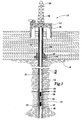
- FIG. 1 several apparatuses for gravel packing an interval of a wellbore operating from an offshore oil and gas platform are schematically illustrated and generally designated 10.
- a semi-submersible platform 12 is centered over a submerged oil and gas formation 14 located below sea floor 16.
- a subsea conduit 18 extends from deck 20 of platform 12 to wellhead installation 22 including blowout preventers 24.
- Platform 12 has a hoisting apparatus 26 and a derrick 28 for raising and lowering pipe strings such as work sting 30.
- a wellbore 32 extends through the various earth strata including formation 14.
- a casing 34 is cemented within wellbore 32 by cement 36.
- Work string 30 include various tools including apparatuses 38, 40, 42 for gravel packing an interval of wellbore 32 adjacent to formation 14 between packers 44, 46 and into annular region or interval 48.
- apparatuses 38, 40, 42 are positioned adjacent to formation 14 including perforations 50.
- a fluid slurry including a liquid carrier and a particulate material such as gravel is pumped down workstring 30.
- the fluid slurry may be injected entirely into apparatus 38 and sequentially flow through apparatuses 40, 42. During this process, portions of the fluid slurry exit each apparatus 38, 40, 42 such that the fluid slurry enters annular interval 48. Once in annular interval 48, a portion the gravel in the fluid slurry is deposited therein. Some of the liquid carrier may enter formation 14 through perforation 50 while the remainder of the fluid carrier, along with some of the gravel, reenters certain sections of apparatuses 38, 40, 42 depositing gravel therein. As numerous sections of sand control screens (not pictured) are positioned within apparatuses 38, 40, 42, the gravel remaining in the fluid slurry is disallowed from further migration.
- the liquid carrier can travel through the sand control screens and up to the surface in a known manner, such as through a wash pipe and into the annulus 52 above packer 44.
- the fluid slurry is pumped down workstring 30 through apparatuses 38, 40, 42 until annular interval 48 surrounding apparatuses 38, 40, 42 and portions of apparatuses 38, 40, 42 are filled with gravel.
- all or a portion of the fluid slurry could be injected directly into annular interval 48 in a known manner such as through a crossover tool (not pictured) which allows the slurry to travel from the interior of workstring 30 to the exterior of workstring 30.
- a crossover tool not pictured
- a portion of the gravel in the fluid slurry is deposited in annular interval 48.
- Some of the liquid carrier may enter formation 14 through perforation 50 while the remainder of the fluid carrier along with some of the gravel enters certain sections of apparatuses 38, 40, 42 depositing gravel therein.
- the sand control screens (not pictured) within apparatuses 38, 40, 42 disallow further migration of the gravel but allows the liquid carrier to travel therethrough and up to the surface. If the fluid slurry is entirely or partially injected directly into annular interval 48 and a sand bridge forms, the fluid slurry will be diverted into apparatuses 38, 40, 42 to bypass this sand bridge such that a complete pack can nonetheless be achieved.
- figure 1 depicts a vertical well
- the apparatus for gravel packing an interval of a wellbore of the present invention is equally well-suited for use in deviated wells, inclined wells or horizontal wells.
- figure 1 depicts an offshore operation
- the apparatus for gravel packing an interval of a wellbore of the present invention is equally well-suited for use in onshore operations.
- Apparatus 60 has an outer tubular 62.
- a portion of the side wall of outer tubular 62 is an axially extending production section 64 that includes a plurality of openings 66.
- Another portion of the side wall of outer tubular 62 is an axially extending non-production section 68 that includes one or more outlets 70.
- the density of opening 66 within production section 64 of outer tubular 62 is much greater than the density of outlets 70 in non-production section 68 of outer tubular 62.
- openings 66 and outlet 70 may alternatively be used without departing from the principles of the present invention.
- openings 66 could alternatively be larger or smaller than outlet 70 without departing from the principles of the present invention.
- the exact number, size and shape of openings 66 are not critical to the present invention, so long as sufficient area is provided for fluid production therethrough and the integrity of outer tubular 62 is maintained.
- channels 72 Disposed within outer tubular 62 and on opposite sides of each other is a pair of channels 72, only one channel 72 being visible.
- Channels 72 provide substantial circumferential fluid isolation between production section 64 and non-production section 68 of outer tubular 62 with pressure relief capability as explained in more detail below.
- channels 72 define the circumferential boundary between a slurry passageway 74, having an outer radial boundary defined by non-production section 68 of outer tubular 62 and a production pathway 76, having an outer radial boundary defined by production section 64 of outer tubular 62.
- Sand control screen assembly 78 includes a base pipe 80 that has a plurality of openings 82 which allow the flow of production fluids into the production tubing.
- the exact number, size and shape of openings 82 are not critical to the present invention, so long as sufficient area is provided for fluid production and the integrity of base pipe 80 is maintained.
- a fluid-porous, particulate restricting, sintered metal material such as plurality of layers of a wire mesh that are sintered together to form a porous sintered wire mesh screen 84.
- Screen 84 is designed to allow fluid flow therethrough but prevent the flow of particulate materials of a predetermined size from passing therethrough.
- a screen housing 86 Positioned around screen 84 is a screen housing 86 that has a plurality of openings 88 which allow the flow of production fluids therethrough.
- the exact number, size and shape of openings 88 is not critical to the present invention, so long as sufficient area is provided for fluid production and the integrity of housing 86 is maintained.
- a wire wrap screen assembly 90 may alternately be used.
- Screen assembly 90 has a base pipe 92 that has a plurality of openings 94.
- a plurality of ribs 96 are spaced around base pipe 92.
- Ribs 96 are generally symmetrically distributed about the axis of base pipe 92.
- Ribs 96 are depicted as having a cylindrical cross section, however, it should be understood by one skilled in the art that ribs 96 may alternatively have a rectangular or triangular cross section or other suitable geometry.
- the exact number of ribs 96 will be dependent upon the diameter of base pipe 92 as well as other design characteristics that are well known in the art.
- ribs 96 and screen wire 98 Wrapped around ribs 96 is a screen wire 98.
- Screen wire 98 forms a plurality of turns, such as turn 100, turn 102 and turn 104. Between each of the turns is a gap through which formation fluids flow. The number of turns and the gap between the turns are determined based upon the characteristics of the formation from which fluid is being produced and the size of the gravel to be used during the gravel packing operation.
- ribs 96 and screen wire 98 may form a sand control screen jacket which is attached to base pipe 92 by welding or other suitable technique.
- Outer tubular 110 has two axially extending production sections 118, 120 each including a plurality of openings 122.
- Outer tubular 110 also has two axially extending non-production sections 124, 126, only one of which is visible in figure 3.
- Each non-production section 124, 126 includes several outlets 128.
- outer tubular 112 has two axially extending production sections 130, 132, only one of which is visible in figure 3.
- Each production section 130, 132 includes a plurality of openings 134.
- Outer tubular 112 also has two axially extending non-production sections 136, 138, each of which includes several outlets 140.
- FIG 4 depicts outer tubular 110 and outer tubular 112 at a ninety-degree circumferential phase shift relative to one another, any degree of circumferential phase shift is acceptable using the present invention as the relative circumferential positions of adjoining sections of the apparatuses for gravel packing an interval of a wellbore of the present invention does not affect the operation of the present invention.
- the mating of adjoining sections of the apparatuses for gravel packing an interval of a wellbore of the present invention is substantially similar to mating typical joints of pipe to form a pipe string requiring no special coupling tools or techniques.
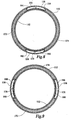
- Screen assembly 114 includes screen housing 142 having a plurality of perforations 144, porous sintered wire mesh screen 146 and base pipe 148 having a plurality of perforations 150, as best seen in figure 6.
- screen assembly 116 includes screen housing 152 having a plurality of perforations 154, a porous sintered wire mesh screen 156 and base pipe 158 having a plurality of perforations 160, as best seen in figure 7.
- channels 166, 168 Positioned adjacent to screen assembly 116 are channels 166, 168.
- screen assembly 114 and channels 162, 164 would be positioned within outer tubular 110 and screen assembly 116 and channels 166, 168 would be positioned within outer tubular 112, as best seen in figures 6 and 7, respectively.
- Channels 162, 164 are circumferentially aligned with non-production sections 124, 126 of outer tubular 110, as best seen in figure 6.
- Channels 166, 168 are circumferentially aligned with non-production sections 136, 138 of outer tubular 112, as best seen in figure 7.
- channels 162, 164 are attached to outer tubular 110 with studs 170.
- channels 166, 168 are attached to outer tubular 112 with studs 170.
- Studs 170 have heads that are received by the channels and shanks that extend into the openings of an outer tubular, such as certain of the openings 128 of outer tubular 110 and certain of the openings 140 of outer tubular 112. The shank portion of studs 170 is welded within the openings to secure channels 162, 164, 166, 168 in their respective positions.
- each channel is inserted into the inside of an outer tubular such that the studs are aligned with openings in the outer tubular.
- the studs may then be extended through the openings by pushing the channels radially outwardly to a predetermined distance toward the inner surface of the outer tubular.
- the studs may then be welded to the outer tubular. Any portion of the stud extending beyond the outer surface of the outer tubular may be ground off to create a substantially smooth outer surface on the outer tubular.
- attachment device described with reference to figures 4-7 is a stud
- other attachment devices or methods could alternatively be used without departing from the principles of the present invention, including, but not limited to, threaded bolts or welding the channel directly to the outer tubular or attaching the channel directly to the sand control screen.
- isolation members are attached to adjacent sections of the outer tubulars, channels and screen housings to help direct the flow of the gravel slurry from the slurry passageways defined by channels 162, 164 to the slurry passageways defined by channels 166, 168.
- the slurry passageways of adjacent sections of the apparatuses for gravel packing an interval of a wellbore of the present invention are in fluid communication with one another such that a fluid slurry may travel in and between these passageways from one section of the apparatuses for gravel packing an interval of a wellbore of the present invention to the next.
- an annular region 180 exists between outer tubulars 110, 112 and screen assemblies 114, 116 that allows the fluid slurry to travel from slurry passageways 182, 184 through annular regions 180 into slurry passageways 186, 188. Accordingly, regardless of the circumferential orientation of outer tubular 110 relative to outer tubular 112, the fluid slurry will travel down through each section of the apparatuses for gravel packing an interval of a wellbore of the present invention.
- Apparatus 200 is similar to that shown in figures 6 and 8 except apparatus 200 has a single slurry passageway 202 and a single production pathway 204. Specifically, apparatus 200 has an outer tubular 206 including a production section 208 having a plurality of openings 210 and a non-production section 212. Apparatus 200 is positioned over sand control screen assembly 114 including screen housing 142 having perforations 144, screen 146 and base pipe 148 having a plurality of perforations 150.
- a channel 214 is positioned between outer tubular 206 and screen assembly 114 which defines slurry passageway 202.
- Channel 214 is attached to outer tubular 206 with a plurality of studs 170.
- An isolation member 216 helps direct the fluid slurry as described above.
- Apparatus 220 is similar to that shown in figures 6 and 8 except apparatus 220 has four slurry passageways 222, 224, 226, 228. Specifically, apparatus 220 has an outer tubular 230 including a plurality of openings 232. Apparatus 220 is position around sand control screen assembly 114. Four channels 234, 236, 238, 240 are attached to outer tubular 230. Four isolation members 242, 244, 246, 247 are positioned between outer tubular 230 and sand control screen assembly 114.
- the apparatus for gravel packing an interval of a wellbore of the present invention may have a variety of configurations including configuration having one, two and four slurry passageways. Other configurations having other numbers of slurry passageways are also possible and are considered within the scope of the present invention.
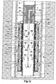
- Wash pipe 254 extends into cross-over assembly 250 such that return fluid passing through screen assembly 252, indicated by arrows 256, may travel through wash pipe 254, as indicated by arrow 258, and into annulus 52, as indicted by arrow 260, for return to the surface.
- the fluid slurry containing gravel is pumped down work string 30 into cross-over assembly 250 along the path indicated by arrows 262.
- the fluid slurry containing gravel exits cross-over assembly 250 through cross-over ports 264 and is discharged into apparatus 248 as indicated by arrows 266.
- the fluid slurry containing gravel then travels between channels 268 and the non-production sections of the outer tubular of apparatus 248 as indicated by arrows 270. At this point, portions of the fluid slurry containing gravel exit apparatus 248 through outlets 272 as indicated by arrows 274.
- the apparatus for gravel packing an interval of a wellbore of the present invention is used to distribute the fluid slurry to various locations within the interval to be gravel packed by injecting the fluid slurry into the slurry passageways created by the channels and the outer tubular of one or more sections of the apparatuses.
- the fluid slurry exits through the various outlets along the slurry passageway and enters the annulus between the apparatus and the wellbore which may be cased or uncased.
- a portion of the gravel in the fluid slurry is deposited around the apparatus in the annulus such that the gravel migrates both circumferentially and axially from the outlets. This process progresses along the entire length of the apparatus such that the annular area becomes completely packed with the gravel.
- a portion of the fluid slurry enters the opening in the production sections of the outer tubular which provides for the deposit of a portion of the gravel from the fluid slurry in the production pathways between the outer tubulars and the sand control screen assemblies. Again, this process progresses along the entire length of the apparatus such that each production pathway becomes completely packed with the gravel. Once both the annulus and the production pathways are completely packed with gravel, the gravel pack operation may cease.
- the fluid slurry may not only be injected into the slurry passageways, but also injected directly into the annulus between the apparatus and the wellbore, as best seen in figure 15.
- the primary path for the fluid slurry containing gravel as it is discharged from exit ports 264 is directly into annular interval 48 as indicated by arrows 280. This is the primary path as the fluid slurry seeks the path of least resistance. Under ideal conditions, the fluid slurry travels throughout the entire interval 48 until interval 48 is completely packed with gravel.
- the fluid slurry enters the production pathways of apparatus 248 such that the annulus between apparatus 248 and sand control screen assembly 252 is also completely packed with gravel.
- sand bridges commonly form during the gravel packing of an interval when the fluid slurry is pumped directly into annular interval 48. These sand bridges are bypassed using the apparatus for gravel packing on an interval of a wellbore of the present invention by first allowing the fluid slurry to pass through the outer tubular into the production pathways of apparatus 248, bypass the sand bridge and then return to annular interval 48 through the outer tubular to complete the gravel packing process. These pathways are considered the secondary path for the fluid slurry. If a sand bridge forms in the secondary paths prior to completing the gravel packing operation, then the fluid slurry enters channels 268 as indicated by arrows 266 and as described above with reference to figure 14. In this embodiment, the channels 268 are considered the tertiary path for the fluid slurry.
- the apparatus for gravel packing an interval of a wellbore of the present invention allows for a complete gravel pack of an interval so that particulate materials in the formation fluid are filtered out.
- FIG 16. One of the unique features of the apparatus for gravel packing an interval of a wellbore of the present invention is illustrated in figure 16.
- the channels used to create the slurry passageways in the present invention have pressure relief capability which prevent catastrophic failures such as those which have occurred with the uses of shunt tubes.
- a channel 300 is positioned between an outer tubular 302 and a screen housing 304.
- no attachment member such as studs 170 described above, is visibly attaching channel 300 to outer tubular 302.
- the attachment members are positioned at preselected intervals along the length of channel 300.
- an outlet 306 is depicted which allows for the discharge of the fluid slurry containing gravel from slurry passageway 308.
- two openings 310 in outer tubular 302 which represent the entries into the production pathways of outer tubular 302.
- Gap 312 exists between the web 314 of channel 302 and the outer surface of screen housing 304. Gap 312 will typically be filled with gravel during a gravel packing operation as the fluid slurry containing gravel will exit outlets 306, reenter outer tubular 302 through openings 310 and migrate into gap 312 as the gravel fills annulus 316 between outer tubular 302 and screen housing 304. It should be noted that gaps 312 also allow production fluids to be produced through this area of screen housing 304 since channel 300 does not impede such flow.
- channel 300 will deform instead of failing. Specifically, web 314 of channel 300 will deform as shown in the dotted section 318 of web 314. Web 314 can deform until it makes contact with the outer surface of screen housing 304.
- the sides 320 of channel 300 may also deform as shown in the dotted sections 322 of channel 300. As sides 320 deform, the contact between sides 320 and the inner surface of outer tubular 302 increase which enhances the seal between the two. Also, such flexure tends to reduce to possibility of having sand lockages in slurry passageway 308. In fact, under sufficient pressure conditions, sides 320 will deform to allow discharge of the fluid slurry between sides 320 and the inside surface of outer tubular 302, thereby providing pressure relief and avoiding damage to channel 300.
- channel 300 will return substantially to its original shape such that normal operation may continue.
- this gravel will tend to provide a seal between sides 320 and the inner surface of outer tubular 302 even if channel 300 does not fully return to its original position.
- channel 300 may be formed from a sheet metal such as a 16-gage 316 L stainless steel. Other thicknesses of sheet metal have also been found suitable for the construction of channel 300 including, but not limited to, sheet metals between about 12-gage and 20-gage.
- channel 300 may be constructed from other materials including, but not limited to, other stainless steels such as 304 stainless steel.
- the pressure relief capability of the present invention can be alternatively achieved by attaching the channels to the screen housing instead of to the outer tubular.
- a channel 330 is positioned between an outer tubular 332 and a screen housing 334.
- an outlet 336 is depicted which allows for the discharge of the fluid slurry containing gravel from slurry passageway 338.
- two openings 340 in outer tubular 332 which represent the entries into the production pathways of outer tubular 332.
- channel 330 is attached to screen housing 334 by one or more welds 342.
- channel 330 is attached to screen housing 334 then outer tubular 332 is positioned around the sand control screen and channel assembly to create slurry passageway 338.
- sides 344 are in contact with the inner surface of outer tubular 332.
- channel 330 will deform instead of failing.
- the sides 344 of channel 330 will deform and, under sufficient pressure conditions, sides 344 will allow discharge of the fluid slurry between sides 344 and the inner surface of outer tubular 332, thereby providing pressure relief and avoiding damage to channel 330.
- channel 330 will return substantially to its original shape such that normal operation may continue.
- a channel 350 is positioned between an outer tubular 352 and a screen housing 354.
- a stud 356 is depicted which attaches channel 350 to outer tubular 352 such that a slurry passageway 358 is formed.
- openings 360 in outer tubular 352 which represent the entries into the production pathways of outer tubular 352.
- Channel 350 includes a web 362, depicted in solid lines, that creates a gap 364 that has a substantially uniform thickness.
- channels 350 are depicted as having sides with square ends that contact the inner surface of outer tubular 352.
- a channel 380 is positioned between an outer tubular 382 and a screen housing 384.
- Outer tubular 382 includes an outlet 386 for the discharge of the fluid slurry from slurry passageway 388.
- Outer tubular 382 also includes openings 390 which are the entries to the production pathways of outer tubular 382.
- no attachment member such as studs 170 described above, is visibly attaching channel 380 to outer tubular 382.
- retainer members 392 are used to hold channel 380 in place.
- channel 380 is allowed to move radially between screen housing 384 and outer tubular 383 during operation and installation, thereby accounting for variations in the annular space between screen housing 384 and outer tubular 383 caused by tolerance in outer tubular 383. Accordingly, ends 396 of channel 380 can move radially relative to retainer members 392, however, a close relationship between ends 396 and retainer members 392 may be maintained to effect a seal.
- retainer members 392 are attached to outer tubular 382 with threaded bolts 394, however, other types of attachment members, such as rivets or the like, may be used.
- Retainer members 392 may extend substantially along the entire length of channel 380 or a plurality of retainer members 392 may be places at intervals along the length of channel 380.
- channel 380 may receive threaded bolts or other types of attachment members directly into ends 396 of channel 380.
Landscapes
- Geology (AREA)
- Life Sciences & Earth Sciences (AREA)
- Engineering & Computer Science (AREA)
- Mining & Mineral Resources (AREA)
- Environmental & Geological Engineering (AREA)
- Fluid Mechanics (AREA)
- Physics & Mathematics (AREA)
- General Life Sciences & Earth Sciences (AREA)
- Geochemistry & Mineralogy (AREA)
- Chemical & Material Sciences (AREA)
- Dispersion Chemistry (AREA)
- Revetment (AREA)
- Investigation Of Foundation Soil And Reinforcement Of Foundation Soil By Compacting Or Drainage (AREA)
- Details Of Valves (AREA)
Abstract
Description
Claims (10)
- An apparatus for gravel packing an interval of a wellbore, the apparatus comprising: a sand control screen positioned within the wellbore; a tubular member disposed within the wellbore forming a first annulus with the sand control screen and a second annulus with the wellbore, the tubular member having an axially extending production section with a plurality of openings and an axially extending non-production section with a plurality of outlets; and a channel disposed within the first annulus that is substantially circumferentially aligned with the non-production section of the tubular member forming a slurry passageway therewith.
- Apparatus according to claim 1, wherein the channel further comprises a web and a pair of oppositely disposed sides.
- Apparatus according to claim 2, wherein the tubular member has an inner surface, and wherein the sides contact the inner surface of the tubular member when the pressure within the slurry passageway is below a predetermined value and at least one of the sides partially separating from the inner surface of the tubular member when the pressure within the slurry passageway is above the predetermined value.
- Apparatus according to claim 2 or 3, wherein the web and each of the sides have an angle therebetween of between about 45 and 90 degrees.
- Apparatus according to claim 2, 3 or 4, wherein the sides have square ends.
- Apparatus according to claim 2, 3, 4 or 5, wherein an attachment member is used to connect the web of the channel to the tubular member.
- A method for gravel packing an interval of a wellbore, the method comprising the steps of: traversing a formation with the wellbore; locating a sand control screen within the wellbore proximate the formation; positioning a tubular member within the wellbore forming a first annulus with the sand control screen and a second annulus with the wellbore, the tubular member having an axially extending production section with a plurality of openings and an axially extending non-production section with a plurality of outlets; disposing a channel within the first annulus such that the channel is substantially circumferentially aligned with the non-production section of the tubular member forming a slurry passageway therewith; injecting a fluid slurry containing gravel through the slurry passageway such that the fluid slurry exits the slurry passageway through the outlets; and terminating the injecting when the interval is substantially completely packed with the gravel.
- A method according to claim 7, wherein the channel has a web and a pair of oppositely disposed sides.
- A method according to claim 8, further comprising the steps of contacting the sides of the channel with an inner surface of the tubular member when the pressure within the slurry passageway is below a predetermined value; and relieving pressure from the slurry passageway by allowing at least one of the sides to partially separate from the inner surface of the tubular member when the pressure within the slurry passageway is above the predetermined value
- A method according to claim 8 or 9, further comprising the step of forming the channel such that the angle between the web and each of the sides is between about 45 and 90 degrees.
Applications Claiming Priority (2)
| Application Number | Priority Date | Filing Date | Title |
|---|---|---|---|
| US09/906,520 US6516882B2 (en) | 2001-07-16 | 2001-07-16 | Apparatus and method for gravel packing an interval of a wellbore |
| US906520 | 2001-07-16 |
Publications (2)
| Publication Number | Publication Date |
|---|---|
| EP1277914A2 true EP1277914A2 (en) | 2003-01-22 |
| EP1277914A3 EP1277914A3 (en) | 2004-08-11 |
Family
ID=25422585
Family Applications (1)
| Application Number | Title | Priority Date | Filing Date |
|---|---|---|---|
| EP02254842A Withdrawn EP1277914A3 (en) | 2001-07-16 | 2002-07-10 | Apparatus and method for gravel packing an interval of a wellbore |
Country Status (3)
| Country | Link |
|---|---|
| US (1) | US6516882B2 (en) |
| EP (1) | EP1277914A3 (en) |
| SG (1) | SG106079A1 (en) |
Cited By (1)
| Publication number | Priority date | Publication date | Assignee | Title |
|---|---|---|---|---|
| CN1882760A (en) * | 2003-12-03 | 2006-12-20 | 埃克森美孚上游研究公司 | Wellbore gravel packing apparatus and method |
Families Citing this family (33)
| Publication number | Priority date | Publication date | Assignee | Title |
|---|---|---|---|---|
| US7100690B2 (en) | 2000-07-13 | 2006-09-05 | Halliburton Energy Services, Inc. | Gravel packing apparatus having an integrated sensor and method for use of same |
| US6644406B1 (en) | 2000-07-31 | 2003-11-11 | Mobil Oil Corporation | Fracturing different levels within a completion interval of a well |
| US6789624B2 (en) | 2002-05-31 | 2004-09-14 | Halliburton Energy Services, Inc. | Apparatus and method for gravel packing an interval of a wellbore |
| US6557634B2 (en) | 2001-03-06 | 2003-05-06 | Halliburton Energy Services, Inc. | Apparatus and method for gravel packing an interval of a wellbore |
| US6588506B2 (en) | 2001-05-25 | 2003-07-08 | Exxonmobil Corporation | Method and apparatus for gravel packing a well |
| US6837308B2 (en) * | 2001-08-10 | 2005-01-04 | Bj Services Company | Apparatus and method for gravel packing |
| US6830104B2 (en) * | 2001-08-14 | 2004-12-14 | Halliburton Energy Services, Inc. | Well shroud and sand control screen apparatus and completion method |
| US6772837B2 (en) | 2001-10-22 | 2004-08-10 | Halliburton Energy Services, Inc. | Screen assembly having diverter members and method for progressively treating an interval of a welibore |
| US6776238B2 (en) | 2002-04-09 | 2004-08-17 | Halliburton Energy Services, Inc. | Single trip method for selectively fracture packing multiple formations traversed by a wellbore |
| US6814139B2 (en) * | 2002-10-17 | 2004-11-09 | Halliburton Energy Services, Inc. | Gravel packing apparatus having an integrated joint connection and method for use of same |
| US6978840B2 (en) * | 2003-02-05 | 2005-12-27 | Halliburton Energy Services, Inc. | Well screen assembly and system with controllable variable flow area and method of using same for oil well fluid production |
| US7866394B2 (en) * | 2003-02-27 | 2011-01-11 | Halliburton Energy Services Inc. | Compositions and methods of cementing in subterranean formations using a swelling agent to inhibit the influx of water into a cement slurry |
| US20040211559A1 (en) | 2003-04-25 | 2004-10-28 | Nguyen Philip D. | Methods and apparatus for completing unconsolidated lateral well bores |
| US7140437B2 (en) * | 2003-07-21 | 2006-11-28 | Halliburton Energy Services, Inc. | Apparatus and method for monitoring a treatment process in a production interval |
| US7147054B2 (en) * | 2003-09-03 | 2006-12-12 | Schlumberger Technology Corporation | Gravel packing a well |
| US20050121192A1 (en) * | 2003-12-08 | 2005-06-09 | Hailey Travis T.Jr. | Apparatus and method for gravel packing an interval of a wellbore |
| US7866708B2 (en) * | 2004-03-09 | 2011-01-11 | Schlumberger Technology Corporation | Joining tubular members |
| US20060037752A1 (en) * | 2004-08-20 | 2006-02-23 | Penno Andrew D | Rat hole bypass for gravel packing assembly |
| US7642223B2 (en) * | 2004-10-18 | 2010-01-05 | Halliburton Energy Services, Inc. | Methods of generating a gas in a plugging composition to improve its sealing ability in a downhole permeable zone |
| US7690429B2 (en) | 2004-10-21 | 2010-04-06 | Halliburton Energy Services, Inc. | Methods of using a swelling agent in a wellbore |
| US7891424B2 (en) * | 2005-03-25 | 2011-02-22 | Halliburton Energy Services Inc. | Methods of delivering material downhole |
| US7870903B2 (en) * | 2005-07-13 | 2011-01-18 | Halliburton Energy Services Inc. | Inverse emulsion polymers as lost circulation material |
| US7694745B2 (en) * | 2005-09-16 | 2010-04-13 | Halliburton Energy Services, Inc. | Modular well tool system |
| CA2637040C (en) * | 2006-02-03 | 2014-01-28 | Exxonmobil Upstream Research Company | Wellbore system using shunt tubes |
| US7661476B2 (en) * | 2006-11-15 | 2010-02-16 | Exxonmobil Upstream Research Company | Gravel packing methods |
| NO345459B1 (en) | 2006-11-15 | 2021-02-08 | Exxonmobil Upstream Res Co | Joint arrangement for use in well drilling, method and application |
| US20110139465A1 (en) * | 2009-12-10 | 2011-06-16 | Schlumberger Technology Corporation | Packing tube isolation device |
| US8136589B2 (en) | 2010-06-08 | 2012-03-20 | Halliburton Energy Services, Inc. | Sand control screen assembly having control line capture capability |
| US8584753B2 (en) | 2010-11-03 | 2013-11-19 | Halliburton Energy Services, Inc. | Method and apparatus for creating an annular barrier in a subterranean wellbore |
| CN103261576B (en) | 2010-12-16 | 2016-02-24 | 埃克森美孚上游研究公司 | Communication module and the method completing pit shaft of alternate path gravel pack |
| US9097108B2 (en) * | 2013-09-11 | 2015-08-04 | Baker Hughes Incorporated | Wellbore completion for methane hydrate production |
| AU2013405210B2 (en) | 2013-11-14 | 2016-11-24 | Halliburton Energy Services, Inc. | Gravel packing apparatus having optimized fluid handling |
| CN113738288B (en) * | 2021-09-07 | 2026-05-08 | 陕西三丰石油科技有限公司 | A sand control well completion structure with an easily removable downhole sand control tubing string |
Family Cites Families (39)
| Publication number | Priority date | Publication date | Assignee | Title |
|---|---|---|---|---|
| US2342913A (en) | 1940-04-15 | 1944-02-29 | Edward E Johnson Inc | Deep well screen |
| US2344909A (en) | 1940-04-15 | 1944-03-21 | Edward E Johnson Inc | Deep well screen |
| US4096911A (en) * | 1977-07-05 | 1978-06-27 | Uop Inc. | Channel base well screen |
| US4945991A (en) | 1989-08-23 | 1990-08-07 | Mobile Oil Corporation | Method for gravel packing wells |
| US5293935A (en) * | 1990-10-22 | 1994-03-15 | Halliburton Company | Sintered metal substitute for prepack screen aggregate |
| US5082052A (en) | 1991-01-31 | 1992-01-21 | Mobil Oil Corporation | Apparatus for gravel packing wells |
| US5113935A (en) | 1991-05-01 | 1992-05-19 | Mobil Oil Corporation | Gravel packing of wells |
| US5161613A (en) | 1991-08-16 | 1992-11-10 | Mobil Oil Corporation | Apparatus for treating formations using alternate flowpaths |
| US5161618A (en) | 1991-08-16 | 1992-11-10 | Mobil Oil Corporation | Multiple fractures from a single workstring |
| US5355956A (en) | 1992-09-28 | 1994-10-18 | Halliburton Company | Plugged base pipe for sand control |
| US5333688A (en) | 1993-01-07 | 1994-08-02 | Mobil Oil Corporation | Method and apparatus for gravel packing of wells |
| US5390966A (en) | 1993-10-22 | 1995-02-21 | Mobil Oil Corporation | Single connector for shunt conduits on well tool |
| US5419394A (en) | 1993-11-22 | 1995-05-30 | Mobil Oil Corporation | Tools for delivering fluid to spaced levels in a wellbore |
| US5443117A (en) | 1994-02-07 | 1995-08-22 | Halliburton Company | Frac pack flow sub |
| US5476143A (en) * | 1994-04-28 | 1995-12-19 | Nagaoka International Corporation | Well screen having slurry flow paths |
| US5515915A (en) | 1995-04-10 | 1996-05-14 | Mobil Oil Corporation | Well screen having internal shunt tubes |
| US5588487A (en) | 1995-09-12 | 1996-12-31 | Mobil Oil Corporation | Tool for blocking axial flow in gravel-packed well annulus |
| US5636691A (en) | 1995-09-18 | 1997-06-10 | Halliburton Energy Services, Inc. | Abrasive slurry delivery apparatus and methods of using same |
| US5722490A (en) | 1995-12-20 | 1998-03-03 | Ely And Associates, Inc. | Method of completing and hydraulic fracturing of a well |
| US6047773A (en) | 1996-08-09 | 2000-04-11 | Halliburton Energy Services, Inc. | Apparatus and methods for stimulating a subterranean well |
| US5848645A (en) | 1996-09-05 | 1998-12-15 | Mobil Oil Corporation | Method for fracturing and gravel-packing a well |
| US6116343A (en) | 1997-02-03 | 2000-09-12 | Halliburton Energy Services, Inc. | One-trip well perforation/proppant fracturing apparatus and methods |
| US5842516A (en) | 1997-04-04 | 1998-12-01 | Mobil Oil Corporation | Erosion-resistant inserts for fluid outlets in a well tool and method for installing same |
| US5868200A (en) | 1997-04-17 | 1999-02-09 | Mobil Oil Corporation | Alternate-path well screen having protected shunt connection |
| US5921318A (en) | 1997-04-21 | 1999-07-13 | Halliburton Energy Services, Inc. | Method and apparatus for treating multiple production zones |
| US5890533A (en) | 1997-07-29 | 1999-04-06 | Mobil Oil Corporation | Alternate path well tool having an internal shunt tube |
| US5881809A (en) | 1997-09-05 | 1999-03-16 | United States Filter Corporation | Well casing assembly with erosion protection for inner screen |
| US5964296A (en) | 1997-09-18 | 1999-10-12 | Halliburton Energy Services, Inc. | Formation fracturing and gravel packing tool |
| US6003600A (en) | 1997-10-16 | 1999-12-21 | Halliburton Energy Services, Inc. | Methods of completing wells in unconsolidated subterranean zones |
| US6481494B1 (en) | 1997-10-16 | 2002-11-19 | Halliburton Energy Services, Inc. | Method and apparatus for frac/gravel packs |
| US6059032A (en) | 1997-12-10 | 2000-05-09 | Mobil Oil Corporation | Method and apparatus for treating long formation intervals |
| US6109356A (en) * | 1998-06-04 | 2000-08-29 | Halliburton Energy Services, Inc. | Well completion tool having pressure relief capability incorporated therein and associated method |
| US6125932A (en) * | 1998-11-04 | 2000-10-03 | Halliburton Energy Services, Inc. | Tortuous path sand control screen and method for use of same |
| US6230803B1 (en) | 1998-12-03 | 2001-05-15 | Baker Hughes Incorporated | Apparatus and method for treating and gravel-packing closely spaced zones |
| US6227303B1 (en) | 1999-04-13 | 2001-05-08 | Mobil Oil Corporation | Well screen having an internal alternate flowpath |
| US6220345B1 (en) | 1999-08-19 | 2001-04-24 | Mobil Oil Corporation | Well screen having an internal alternate flowpath |
| US6343651B1 (en) | 1999-10-18 | 2002-02-05 | Schlumberger Technology Corporation | Apparatus and method for controlling fluid flow with sand control |
| US6298916B1 (en) | 1999-12-17 | 2001-10-09 | Schlumberger Technology Corporation | Method and apparatus for controlling fluid flow in conduits |
| US6644406B1 (en) | 2000-07-31 | 2003-11-11 | Mobil Oil Corporation | Fracturing different levels within a completion interval of a well |
-
2001
- 2001-07-16 US US09/906,520 patent/US6516882B2/en not_active Expired - Lifetime
-
2002
- 2002-07-10 EP EP02254842A patent/EP1277914A3/en not_active Withdrawn
- 2002-07-10 SG SG200204202A patent/SG106079A1/en unknown
Cited By (3)
| Publication number | Priority date | Publication date | Assignee | Title |
|---|---|---|---|---|
| CN1882760A (en) * | 2003-12-03 | 2006-12-20 | 埃克森美孚上游研究公司 | Wellbore gravel packing apparatus and method |
| US7475725B2 (en) | 2003-12-03 | 2009-01-13 | Exxonmobil Upstream Research Company | Wellbore gravel packing apparatus and method |
| CN1882760B (en) * | 2003-12-03 | 2012-10-03 | 埃克森美孚上游研究公司 | Wellbore gravel packing apparatus and method |
Also Published As
| Publication number | Publication date |
|---|---|
| US6516882B2 (en) | 2003-02-11 |
| SG106079A1 (en) | 2004-09-30 |
| EP1277914A3 (en) | 2004-08-11 |
| US20030010496A1 (en) | 2003-01-16 |
Similar Documents
| Publication | Publication Date | Title |
|---|---|---|
| US6516882B2 (en) | Apparatus and method for gravel packing an interval of a wellbore | |
| US6702018B2 (en) | Apparatus and method for gravel packing an interval of a wellbore | |
| US6789624B2 (en) | Apparatus and method for gravel packing an interval of a wellbore | |
| US6516881B2 (en) | Apparatus and method for gravel packing an interval of a wellbore | |
| US6581689B2 (en) | Screen assembly and method for gravel packing an interval of a wellbore | |
| US6814139B2 (en) | Gravel packing apparatus having an integrated joint connection and method for use of same | |
| US9988882B2 (en) | Gravel packing apparatus having locking jumper tubes | |
| CN1188585C (en) | Well screen having an internal alternate flowpath | |
| US8967240B2 (en) | Gravel packing apparatus having a jumper tube protection assembly | |
| US6715545B2 (en) | Transition member for maintaining for fluid slurry velocity therethrough and method for use of same | |
| US9580999B2 (en) | Gravel packing apparatus having a jumper tube protection assembly | |
| GB2571028B (en) | Gravel packing apparatus having a jumper tube protection assembly | |
| AU2016216652B2 (en) | Gravel Packing Apparatus Having Locking Jumper Tubes | |
| US20030188865A1 (en) | Method for assembly of a gravel packing apparatus having expandable channels | |
| GB2567351B (en) | Gravel packing apparatus having locking jumper tubes | |
| AU2016213868A1 (en) | Gravel packing apparatus having a rotatable slurry delivery subassembly |
Legal Events
| Date | Code | Title | Description |
|---|---|---|---|
| PUAI | Public reference made under article 153(3) epc to a published international application that has entered the european phase |
Free format text: ORIGINAL CODE: 0009012 |
|
| AK | Designated contracting states |
Kind code of ref document: A2 Designated state(s): AT BE BG CH CY CZ DE DK EE ES FI FR GB GR IE IT LI LU MC NL PT SE SK TR |
|
| AX | Request for extension of the european patent |
Free format text: AL;LT;LV;MK;RO;SI |
|
| PUAL | Search report despatched |
Free format text: ORIGINAL CODE: 0009013 |
|
| AK | Designated contracting states |
Kind code of ref document: A3 Designated state(s): AT BE BG CH CY CZ DE DK EE ES FI FR GB GR IE IT LI LU MC NL PT SE SK TR |
|
| AX | Request for extension of the european patent |
Extension state: AL LT LV MK RO SI |
|
| RIC1 | Information provided on ipc code assigned before grant |
Ipc: 7E 21B 43/08 B Ipc: 7E 21B 43/04 A |
|
| 17P | Request for examination filed |
Effective date: 20041005 |
|
| STAA | Information on the status of an ep patent application or granted ep patent |
Free format text: STATUS: THE APPLICATION HAS BEEN WITHDRAWN |
|
| 18W | Application withdrawn |
Effective date: 20041224 |