EP1277844A1 - Moving-hearth heating furnace and method for making reduced metal agglomerates - Google Patents
Moving-hearth heating furnace and method for making reduced metal agglomerates Download PDFInfo
- Publication number
- EP1277844A1 EP1277844A1 EP02254726A EP02254726A EP1277844A1 EP 1277844 A1 EP1277844 A1 EP 1277844A1 EP 02254726 A EP02254726 A EP 02254726A EP 02254726 A EP02254726 A EP 02254726A EP 1277844 A1 EP1277844 A1 EP 1277844A1
- Authority
- EP
- European Patent Office
- Prior art keywords
- moving
- hearth
- agglomerates
- heating furnace
- metal oxide
- Prior art date
- Legal status (The legal status is an assumption and is not a legal conclusion. Google has not performed a legal analysis and makes no representation as to the accuracy of the status listed.)
- Granted
Links
- 238000010438 heat treatment Methods 0.000 title claims abstract description 40
- 229910052751 metal Inorganic materials 0.000 title claims abstract description 28
- 239000002184 metal Substances 0.000 title claims abstract description 28
- 238000000034 method Methods 0.000 title claims abstract description 23
- 239000000843 powder Substances 0.000 claims abstract description 41
- 229910044991 metal oxide Inorganic materials 0.000 claims abstract description 32
- 150000004706 metal oxides Chemical class 0.000 claims abstract description 32
- 230000003028 elevating effect Effects 0.000 claims abstract description 13
- 239000003575 carbonaceous material Substances 0.000 claims abstract description 9
- 230000008021 deposition Effects 0.000 claims abstract description 4
- UQSXHKLRYXJYBZ-UHFFFAOYSA-N Iron oxide Chemical compound [Fe]=O UQSXHKLRYXJYBZ-UHFFFAOYSA-N 0.000 claims description 89
- 238000007789 sealing Methods 0.000 claims description 19
- 238000005192 partition Methods 0.000 claims description 18
- 239000000463 material Substances 0.000 claims description 11
- 238000007599 discharging Methods 0.000 claims description 5
- XLYOFNOQVPJJNP-UHFFFAOYSA-N water Substances O XLYOFNOQVPJJNP-UHFFFAOYSA-N 0.000 claims description 5
- 238000012423 maintenance Methods 0.000 abstract description 10
- 230000015572 biosynthetic process Effects 0.000 abstract description 6
- XEEYBQQBJWHFJM-UHFFFAOYSA-N Iron Chemical compound [Fe] XEEYBQQBJWHFJM-UHFFFAOYSA-N 0.000 description 58
- 235000013980 iron oxide Nutrition 0.000 description 45
- 229910052742 iron Inorganic materials 0.000 description 14
- 239000008188 pellet Substances 0.000 description 10
- 239000007789 gas Substances 0.000 description 8
- VNWKTOKETHGBQD-UHFFFAOYSA-N methane Chemical compound C VNWKTOKETHGBQD-UHFFFAOYSA-N 0.000 description 8
- 238000007796 conventional method Methods 0.000 description 4
- 239000003345 natural gas Substances 0.000 description 4
- 239000002994 raw material Substances 0.000 description 4
- 239000003245 coal Substances 0.000 description 3
- 210000004907 gland Anatomy 0.000 description 3
- 238000012856 packing Methods 0.000 description 3
- WGLPBDUCMAPZCE-UHFFFAOYSA-N Trioxochromium Chemical compound O=[Cr](=O)=O WGLPBDUCMAPZCE-UHFFFAOYSA-N 0.000 description 2
- 229910000423 chromium oxide Inorganic materials 0.000 description 2
- 229910000428 cobalt oxide Inorganic materials 0.000 description 2
- IVMYJDGYRUAWML-UHFFFAOYSA-N cobalt(ii) oxide Chemical compound [Co]=O IVMYJDGYRUAWML-UHFFFAOYSA-N 0.000 description 2
- 238000001816 cooling Methods 0.000 description 2
- 238000000151 deposition Methods 0.000 description 2
- VBMVTYDPPZVILR-UHFFFAOYSA-N iron(2+);oxygen(2-) Chemical class [O-2].[Fe+2] VBMVTYDPPZVILR-UHFFFAOYSA-N 0.000 description 2
- 239000000203 mixture Substances 0.000 description 2
- 229910000480 nickel oxide Inorganic materials 0.000 description 2
- GNRSAWUEBMWBQH-UHFFFAOYSA-N oxonickel Chemical compound [Ni]=O GNRSAWUEBMWBQH-UHFFFAOYSA-N 0.000 description 2
- 238000007790 scraping Methods 0.000 description 2
- OKTJSMMVPCPJKN-UHFFFAOYSA-N Carbon Chemical compound [C] OKTJSMMVPCPJKN-UHFFFAOYSA-N 0.000 description 1
- 229910052799 carbon Inorganic materials 0.000 description 1
- 230000015556 catabolic process Effects 0.000 description 1
- 239000003638 chemical reducing agent Substances 0.000 description 1
- 230000003247 decreasing effect Effects 0.000 description 1
- 238000006731 degradation reaction Methods 0.000 description 1
- 230000003111 delayed effect Effects 0.000 description 1
- 238000010586 diagram Methods 0.000 description 1
- 230000005489 elastic deformation Effects 0.000 description 1
- 239000000446 fuel Substances 0.000 description 1
- 238000004519 manufacturing process Methods 0.000 description 1
- 238000001465 metallisation Methods 0.000 description 1
- 230000005855 radiation Effects 0.000 description 1
- 239000011819 refractory material Substances 0.000 description 1
- 238000011160 research Methods 0.000 description 1
- 238000005096 rolling process Methods 0.000 description 1
- 239000000126 substance Substances 0.000 description 1
Images

Classifications
-
- F—MECHANICAL ENGINEERING; LIGHTING; HEATING; WEAPONS; BLASTING
- F27—FURNACES; KILNS; OVENS; RETORTS
- F27D—DETAILS OR ACCESSORIES OF FURNACES, KILNS, OVENS OR RETORTS, IN SO FAR AS THEY ARE OF KINDS OCCURRING IN MORE THAN ONE KIND OF FURNACE
- F27D99/00—Subject matter not provided for in other groups of this subclass
- F27D99/0073—Seals
-
- C—CHEMISTRY; METALLURGY
- C21—METALLURGY OF IRON
- C21B—MANUFACTURE OF IRON OR STEEL
- C21B13/00—Making spongy iron or liquid steel, by direct processes
- C21B13/10—Making spongy iron or liquid steel, by direct processes in hearth-type furnaces
- C21B13/105—Rotary hearth-type furnaces
-
- F—MECHANICAL ENGINEERING; LIGHTING; HEATING; WEAPONS; BLASTING
- F27—FURNACES; KILNS; OVENS; RETORTS
- F27B—FURNACES, KILNS, OVENS OR RETORTS IN GENERAL; OPEN SINTERING OR LIKE APPARATUS
- F27B3/00—Hearth-type furnaces, e.g. of reverberatory type; Electric arc furnaces ; Tank furnaces
- F27B3/10—Details, accessories or equipment, e.g. dust-collectors, specially adapted for hearth-type furnaces
-
- F—MECHANICAL ENGINEERING; LIGHTING; HEATING; WEAPONS; BLASTING
- F27—FURNACES; KILNS; OVENS; RETORTS
- F27B—FURNACES, KILNS, OVENS OR RETORTS IN GENERAL; OPEN SINTERING OR LIKE APPARATUS
- F27B9/00—Furnaces through which the charge is moved mechanically, e.g. of tunnel type; Similar furnaces in which the charge moves by gravity
- F27B9/14—Furnaces through which the charge is moved mechanically, e.g. of tunnel type; Similar furnaces in which the charge moves by gravity characterised by the path of the charge during treatment; characterised by the means by which the charge is moved during treatment
- F27B9/16—Furnaces through which the charge is moved mechanically, e.g. of tunnel type; Similar furnaces in which the charge moves by gravity characterised by the path of the charge during treatment; characterised by the means by which the charge is moved during treatment the charge moving in a circular or arcuate path
-
- F—MECHANICAL ENGINEERING; LIGHTING; HEATING; WEAPONS; BLASTING
- F27—FURNACES; KILNS; OVENS; RETORTS
- F27M—INDEXING SCHEME RELATING TO ASPECTS OF THE CHARGES OR FURNACES, KILNS, OVENS OR RETORTS
- F27M2003/00—Type of treatment of the charge
- F27M2003/16—Treatment involving a chemical reaction
- F27M2003/165—Reduction
Definitions
- the present invention relates to a technique for producing reduced metal agglomerates by heating and reducing metal oxide agglomerates containing a carbonaceous material using a moving-hearth heating furnace.
- the metal oxide agglomerates include agglomerates of a raw material containing iron oxides, nickel oxide, chromium oxide, cobalt oxide, or a mixture of these substances.
- the Midrex process As a method for making reduced iron, the Midrex process is well known.
- a reducing gas formed from natural gas is blown into a shaft furnace through a tuyere so that the shaft furnace is kept in a reducing atmosphere, and iron ore or iron oxide pellets charged in the furnace are reduced by being brought into contact with the reducing gas, and thereby reduced iron is obtained.
- U.S. Patent No. 3,443,931 discloses a process in which fine ore and a carbonaceous material (e.g., coal) are mixed together and pelletized, followed by reducing by heating in a high-temperature atmosphere, to produce reduced iron.
- a carbonaceous material e.g., coal
- dried iron oxide pellets containing a carbonaceous material are fed into a rotary hearth furnace at a given thickness, and the mixture is heated by radiant heat in the furnace while being moved in the furnace, and thereby the iron oxide pellets are reduced by the carbonaceous material.
- the reduced iron oxide pellets are radiation-cooled by a cooling plate, referred to as a chill plate, in the radiation cooling zone, and are then scraped away from the moving hearth by a discharge screw of a discharger and are discharged from the furnace.
- this process is advantageous over the Midrex process in that, for example, fine ore can be directly used, the reduction rate can be increased, and the carbon content in the product can be adjusted.
- powder which is generated from the iron oxide pellets due to various factors, such as rolling, friction, or dropping impact when the pellets are fed into the furnace, is also fed into the furnace together with the pellets.
- the fed powder is deposited on the moving hearth which rotates to form an iron oxide powder layer. Since the iron oxide powder layer includes the carbonaceous material, it is reduced in the same manner as the iron oxide pellets, and thus a reduced iron powder layer is formed. Although a portion of the reduced iron powder is discharged from the furnace by the discharger together with the reduced iron pellets, the other portion of the reduced iron powder remains on the moving hearth and is pressed against the surface of the moving hearth by the discharger.
- the reduced iron powder pressed against the surface of the moving hearth is deposited on the surface of the moving hearth without being reoxidized because of its denseness. Reduced iron powder is further added as the rotary hearth rotates and reduced iron powder is gradually integrated into the previously deposited reduced iron powder to form a reduced iron layer in the shape of a large plate.
- the plate-shaped reduced iron layer (hereinafter referred to as an "iron plate”) may be scraped by the edge of the blade of the discharge screw and the separated reduced iron may be wound around the discharge screw or may prevent the reduced iron from being discharged because of clogging of the discharge port, giving rise to problems, such as shutdown.
- the agglomerates cannot be heated homogeneously, and the rate of reduction varies for each agglomerate, resulting in a degradation in quality of the reduced iron.
- the applicant of the present invention has carried out thorough research on the formation mechanism of the iron plate, and has completed an invention in Japanese Patent No. 3075721 (Prior Art 1).
- the above invention is characterized in that the operation is carried out by continuously or intermittently moving a discharger upward from the surface of a moving hearth, depending on the thickness of the iron oxide layer, so that a gap is provided between the surface of the moving hearth and the discharger.
- the reduced iron powder layer formed on the moving hearth by powder mixed into the furnace together with the iron oxide pellets is reduced to form a reduced iron powder layer
- the reduced iron powder layer is not densified because it is not pressed by a discharger, such as a discharge screw, and the reduced iron powder layer is reoxidized during passing through the furnace again to form an iron oxide layer. Therefore, an iron plate is not formed.
- a discharge screw having a schematic structure shown in Fig. 3 is generally employed.
- a through-hole 26 is provided on the side wall of a moving-hearth furnace, and a screw axis 4 of the discharge screw is extended to the outside of the furnace and is supported by a screw axis bearing 24 arranged outside of the furnace.
- the screw axis 4 is revolved by a drive device for discharger 28 arranged outside of the furnace through a chain or the like.
- an elevating device 22 for moving the screw bearing 24 vertically is provided, and an expansion joint 23, functioning as a gas-sealing means, which is made of metal is also provided so as to prevent air from entering the furnace through the gap between the through-hole 26 and the screw axis 4 and to prevent furnace gas from leaking out of the furnace.
- the metal expansion joint 23 as shown in Fig. 3 in general, since the amount of expansion in a direction perpendicular to the axial direction is smaller than the amount of expansion in the axial direction, it is difficult to secure the amount of vertical movement of the screw axis 4 required for the operation. Furthermore, as vertical movement is repeated, the expansion joint 23 is subjected to repeated elastic deformation in the direction perpendicular to the axial direction, and damage, such as cracks, due to metal fatigue easily occurs. When such damage occurs, in order to replace the expansion joint 23, the screw bearing 24 section must be disassembled by halting the operation, and thus the maintenance work is troublesome.
- the present invention seeks to provide a moving-hearth furnace for producing reduced metal having a means for preventing a metal plate from being formed other than moving a discharger (discharge screw) vertically, so that the maintenance work can be significantly reduced, and to provide a method for operating the same.
- a moving-hearth heating furnace includes a moving hearth which moves with a metal oxide-containing material being placed thereon, a heating furnace for heating the metal oxide-containing material to produce a heat-treated material while the moving hearth is moving in the heating furnace, and a discharger for discharging the heat-treated material from the heating furnace, wherein the moving hearth is movable vertically.
- the moving-hearth heating furnace includes an elevating device for moving the moving hearth vertically, the elevating device being provided on a supporting section for supporting the moving hearth.
- the moving-hearth heating furnace can further comprise a seal plate provided around the entire lower section of the moving hearth and a water-sealing trough fixed on a side wall of the heating furnace, wherein the length of the seal plate and the depth and fixing position of the water-sealing trough are determined so that the lower end of the seal plate is kept being immersed in water in the water-sealing trough when the moving hearth is moved upward to the upper limit.
- the moving-hearth heating furnace can further comprise a columnar partition provided on the moving hearth and a roof having a recess, wherein the top of the columnar partition is inserted into the recess and the height of the columnar partition and the depth of the recess are determined so that the top of the columnar partition does not come out of the recess when the moving hearth is moved downward to the lower limit.
- a method for making reduced metal agglomerates includes the steps of feeding metal oxide agglomerates containing a carbonaceous material onto a moving hearth which moves in a heating furnace, heating and reducing the metal oxide agglomerates to produce reduced metal agglomerates while the moving hearth is moving in the heating furnace, and discharging the reduced metal agglomerates from the heating furnace by a discharger provided above and in close proximity to the moving hearth in the heating furnace.
- the moving hearth is continuously or intermittently moved vertically depending on the thickness of a metal oxide layer formed by the deposition of powder of the metal oxide agglomerates mixed into the heating furnace together with the metal oxide agglomerates so that a gap is provided between the surface of the metal oxide layer and the discharger during operation.
- the rate of moving the moving hearth downward continuously or the amount of moving the moving hearth downward intermittently can be adjusted depending on the amount of powder of the iron oxide agglomerates entering the heating furnace
- the rate of moving said moving hearth downward can be adjusted so that a gap corresponding to three-fourths or less of the average diameter of the agglomerates is provided between the edge of a blade of a discharge screw of the discharger and the surface of the moving hearth or the iron oxide layer.
- the formation of a metal plate can be prevented.
- the maintenance workload for the sealing mechanism of the discharger can be significantly reduced, continuous operation is enabled for a longer period of time, and reduced metal having a high metallization rate can be obtained stably.
- Figs. 1 and 2 show an embodiment of the present invention in the case in which reduced iron, as the reduced metal, is produced using a rotary hearth furnace, as the moving-hearth heating furnace, and using iron oxide agglomerates as the metal oxide agglomerates.
- the rotary hearth furnace includes a furnace shell 1 and a rotary hearth 2.
- the furnace shell 1 does not have the commonly used annular structure including an outer wall, an inner wall, and a roof linking them, as in the conventional method, but has a cap-shaped structure including only an outer wall and a roof, without an inner wall.
- the rotary hearth 2 does not have the commonly used doughnut-shaped structure in which the central section is an empty space, but has a disk-shaped structure having a columnar partition 3 provided in the center and extending upward.
- the reason for employing such a structure is that, as will be described above, a gas sealing means for an inner wall section is not required because an inner wall is eliminated, thus significantly reducing the maintenance work.
- a metallic support frame 5 is disposed in contact with the lower surface of the rotary hearth 2 in order to support the weight of the rotary hearth 2 composed of a refractory material, and so on.
- An annular rail 6, which is concentric with the axis of the rotary hearth 2, is fixed upside down on the lower surface of the support frame 5.
- a plurality of support rollers 7 which support the rail 6 from below are placed on the same circumference as that of the rail 6.
- Each support roller 7 is provided with an elevating device 8.
- a mechanically or electrically synchronizing mechanism is provided between all the provided elevating devices 8.
- the plurality of support rollers 7 are moved vertically at the same time, and the rotary hearth 2 can be elevated via the rail 6 supported by the support rollers 7 and the support frame 5 while the surface of the rotary hearth 2 is kept horizontal.
- Reference numeral 9 represents a rotating axis for rotating the rotary hearth 2 horizontally.
- the rotating axis 9 is rotated by a driving device 17.
- the rotating axis 9 includes an internal cylinder 10 of the rotating axis and an external cylinder 11 of the rotating axis.
- the internal cylinder 10 of the rotating axis is joined to the lower surface of the support frame 5 so as to correspond to the axis of rotation of the rotary hearth 2.
- the external cylinder 11 is rotatably inserted into a support device 13 fixed on the ground (floor) with radial bearings 14 and thrust bearings 15 therebetween.
- the internal cylinder 10 and the external cylinder 11 are connected to each other by a spline mechanism, and the internal cylinder 10 moves smoothly in relation to the external cylinder 11. Therefore, since the internal cylinder 10 moves vertically and contracts in conjunction with the vertical movement by the elevating devices 8 provided on the individual support rollers 7, the rotary hearth 2 is not prevented from being moved vertically.
- a sprocket 12 is mounted on the external cylinder 11.
- the sprocket 12 is connected to a driving device 17 including a motor and a speed reducer via a chain 16. Therefore, by using the rotating axis 9 and the driving device 17, it is possible to move the rotary hearth vertically while rotating the rotary hearth at a desired rotational speed.
- a seal plate 18 is provided around the entire lower section of the rotary hearth 2 like a headband. As the rotary hearth 2 is moved vertically, the seal plate 18 is also moved vertically.
- the seal plate 18 displays a gas-sealing function in a state in which at least the lower end thereof is immersed in water filled in a water-sealing trough 19.
- the water-sealing trough 19 is usually fixed on the side wall of the furnace, etc.
- the length of the seal plate 18 and the depth and fixing position of the water-sealing trough are determined so that the lower end of the seal plate 18 is kept being immersed in water in order to ensure water sealing suitable for the furnace pressure even when the rotary hearth 2 is moved upward to the upper limit and so that the lower end of the seal plate 18 does not hit the bottom of the water-sealing trough 19 even when the rotary hearth 2 is moved downward to the lower limit.
- the columnar partition 3 provided on the rotary hearth 2 is also moved vertically-
- the top of the columnar partition 3 is inserted into a recess 21 which is provided in the center of the roof 20 of the furnace shell 1.
- the height of the columnar partition 3 and the depth of the recess 21 are determined so that the top of the columnar partition 3 does not come out of the recess 21 even when the rotary hearth 2 is moved downward to the lower limit and so that the top of the columnar partition 3 does not hit the bottom of the recess 21 even when the rotary hearth 2 is moved upward to the upper limit.
- the internal diameter of the recess 21 is slightly larger than the external diameter of the columnar partition 3 so that the rotation and vertical movement of the columnar partition 3 are not prevented and a large amount of furnace gas does not flow into the recess 21.
- the columnar partition 3 and the recess 21 it is possible to direct the gas flow in the reduction furnace in the moving direction (or in a direction opposite to the moving direction) of the agglomerates, the same as the case when a furnace shell 1 provided with an inner wall, which is a commonly used structure in the conventional method, is used, and it is also possible to maintain high energy efficiency.
- a gas-sealing means which is required for the inner wall section in the conventional method, is not required. By eliminating the gas-sealing means, the maintenance work is not required in the center of the furnace, and thus the maintenance workload is significantly reduced.
- a sealing mechanism having a simple structure can be employed between the screw axis 4 and a screw axis through-hole 24.
- a gland packing 27 into a gap between the screw axis 4 and the screw axis through-hole 24
- the screw axis 4 is allowed to slide horizontally and gas sealing can be performed without fail.
- the gland packing can also be replaced easily, and thus the maintenance workload is significantly reduced.
- the rate of descending when the rotary hearth 2 is moved downward continuously and the amount of descending when the rotary hearth 2 is moved downward intermittently may be adjusted depending on the amount of powder of the iron oxide agglomerates (hereinafter, simply referred to as "agglomerates") entering the reduction furnace.
- agglomerates powder of the iron oxide agglomerates
- the mass of the powder of the agglomerates entering the furnace together with the iron oxide agglomerates per unit time is determined based on the amount of the iron oxide agglomerates charged and the rate of occurrence of powder of the agglomerates.
- the mass of the metallic iron powder obtained by reduction is determined based on the mass of the powder of the agglomerates from the past operating performance.
- the mass of the metallic iron powder is converted into a volume A based on the bulk density of the metallic iron powder.
- the product of the amount of descending per unit time of the rotary hearth 2 and the area of the hearth is defined as a spatial volume B.
- the rotary hearth 2 is moved downward within the unit time so that the ratio A/B is 50 or less.
- the rate obtained from the past operating performance may be used.
- the ratio A/B exceeds 50, the gap between the edge of the blade of the discharge screw 4 and the surface of the rotary hearth 2 is decreased, and when an iron oxide layer is formed, the iron oxide layer is easily brought into contact with the edge of the blade of the discharge screw 4, and thereby the powder of the agglomerates is strongly compressed into the iron oxide layer. As a result, an iron plate is easily formed on the iron oxide layer. Furthermore, in order to prevent the contact between the iron oxide layer formed on the surface of the moving hearth 2 and the edge of the blade of the discharge screw 4 more reliably, the ratio A/B is preferably 20 or less.
- the rate of descending (or amount of descending) of the rotary hearth 2 may be adjusted so that a gap corresponding to three-fourths or less of the average diameter of the agglomerates is provided between the edge of the blade of the discharge screw 4 and the surface of the rotary hearth 2 or the iron oxide layer. In such a way, it is also possible to prevent the powder of the agglomerates being compressed into the surface of the moving hearth or the iron oxide layer by the edge of the blade of the discharge screw 4, and thus the formation of an iron plate can be prevented.
- the gap between the edge of the blade of the discharge screw 4 and the surface of the moving hearth 2 or the iron oxide layer is three-fourths or more of the average diameter of the agglomerates, it is not possible to discharge reduced iron by the discharge screw 4.
- the gap sufficient for passing the powder of the agglomerates is acceptable.
- the metallic iron powder is not compressed into the iron oxide layer to form an iron plate, and only an iron oxide layer is formed.
- the powder of the agglomerates mixed starts to form an iron oxide layer on the surface of the rotary hearth 2 and the thickness thereof increases, which may obstruct the operation.
- this iron oxide layer is porous because it is not strongly pressed by the edge of the blade of the discharge screw 4. Therefore, it is possible to scrape the iron oxide layer off easily with a cutter or the like.
- the iron oxide layer is porous, even when the iron oxide layer is separated from the surface of the moving hearth 2, the layer is separated in small lumps. Therefore, the separated iron oxide is not wound around the discharge screw 4 or does not cause clogging of the discharge port for reduced iron.
- the furnace shell 1 is cap-shaped, the rotary hearth 2 is disk-shaped, and the columnar partition 3 is provided in the center thereof.
- the present invention is not necessarily limited to this, and the furnace shell may be annular and the rotary hearth may be doughnut-shaped, in the same manner as that of the conventional method.
- the rail 6 is fixed upside down on the lower surface of the rotary hearth 2, and the rollers 7 provided with the elevating devices 8 are provided on the ground (floor) side.
- the present invention is not necessarily limited to this, and a method may be used in which rollers or wheels are fixed on the lower surface of the rotary hearth, a rail is arranged on the ground (floor) side, and a plurality of elevating devices are provided on the lower surface of the rail so that the entire rail is moved vertically.
- the discharge screw axis and the through-hole are sealed with a gland packing.
- the present invention is not limited to this, and an expansion joint similar to that in Prior Art 1 may be used. In such a case, since the discharge screw axis does not move vertically and only expands horizontally, the fatigue life of the expansion joint is sufficiently long, and the maintenance workload due to the replacement of the expansion joint can be reduced.
Landscapes
- Engineering & Computer Science (AREA)
- Mechanical Engineering (AREA)
- General Engineering & Computer Science (AREA)
- Chemical & Material Sciences (AREA)
- Metallurgy (AREA)
- Materials Engineering (AREA)
- Manufacturing & Machinery (AREA)
- Organic Chemistry (AREA)
- Manufacture Of Iron (AREA)
- Tunnel Furnaces (AREA)
- Manufacture And Refinement Of Metals (AREA)
- Vertical, Hearth, Or Arc Furnaces (AREA)
- Furnace Charging Or Discharging (AREA)
Abstract
Description
- The present invention relates to a technique for producing reduced metal agglomerates by heating and reducing metal oxide agglomerates containing a carbonaceous material using a moving-hearth heating furnace. Examples of the metal oxide agglomerates include agglomerates of a raw material containing iron oxides, nickel oxide, chromium oxide, cobalt oxide, or a mixture of these substances.
- As a method for making reduced iron, the Midrex process is well known. In this process, a reducing gas formed from natural gas is blown into a shaft furnace through a tuyere so that the shaft furnace is kept in a reducing atmosphere, and iron ore or iron oxide pellets charged in the furnace are reduced by being brought into contact with the reducing gas, and thereby reduced iron is obtained.
- However, in this method, since natural gas, which is an expensive fuel, must be used to form the reducing gas and a large amount of natural gas must be supplied, an increase in production costs is inevitable.
- Under these circumstances, recently, processes for producing reduced iron using relatively inexpensive coal instead of natural gas as the reducing material have been receiving attention again. For example, U.S. Patent No. 3,443,931 discloses a process in which fine ore and a carbonaceous material (e.g., coal) are mixed together and pelletized, followed by reducing by heating in a high-temperature atmosphere, to produce reduced iron. In this process, dried iron oxide pellets containing a carbonaceous material are fed into a rotary hearth furnace at a given thickness, and the mixture is heated by radiant heat in the furnace while being moved in the furnace, and thereby the iron oxide pellets are reduced by the carbonaceous material. The reduced iron oxide pellets are radiation-cooled by a cooling plate, referred to as a chill plate, in the radiation cooling zone, and are then scraped away from the moving hearth by a discharge screw of a discharger and are discharged from the furnace.
- In addition to the fact that the reducing material is coal-based, this process is advantageous over the Midrex process in that, for example, fine ore can be directly used, the reduction rate can be increased, and the carbon content in the product can be adjusted.
- Although the process has the advantages described above, powder, which is generated from the iron oxide pellets due to various factors, such as rolling, friction, or dropping impact when the pellets are fed into the furnace, is also fed into the furnace together with the pellets. The fed powder is deposited on the moving hearth which rotates to form an iron oxide powder layer. Since the iron oxide powder layer includes the carbonaceous material, it is reduced in the same manner as the iron oxide pellets, and thus a reduced iron powder layer is formed. Although a portion of the reduced iron powder is discharged from the furnace by the discharger together with the reduced iron pellets, the other portion of the reduced iron powder remains on the moving hearth and is pressed against the surface of the moving hearth by the discharger. The reduced iron powder pressed against the surface of the moving hearth is deposited on the surface of the moving hearth without being reoxidized because of its denseness. Reduced iron powder is further added as the rotary hearth rotates and reduced iron powder is gradually integrated into the previously deposited reduced iron powder to form a reduced iron layer in the shape of a large plate. The plate-shaped reduced iron layer (hereinafter referred to as an "iron plate") may be scraped by the edge of the blade of the discharge screw and the separated reduced iron may be wound around the discharge screw or may prevent the reduced iron from being discharged because of clogging of the discharge port, giving rise to problems, such as shutdown.
- A depression exists on the surface of the moving hearth after the iron plate is scraped off, and the charged agglomerates enter the depression. As a result, it is not possible to charge the agglomerates at a given thickness, the agglomerates cannot be heated homogeneously, and the rate of reduction varies for each agglomerate, resulting in a degradation in quality of the reduced iron.
- Under these circumstances, in order to prevent the formation of the iron plate, the applicant of the present invention has carried out thorough research on the formation mechanism of the iron plate, and has completed an invention in Japanese Patent No. 3075721 (Prior Art 1). The above invention is characterized in that the operation is carried out by continuously or intermittently moving a discharger upward from the surface of a moving hearth, depending on the thickness of the iron oxide layer, so that a gap is provided between the surface of the moving hearth and the discharger. In the above invention, although the iron oxide powder layer formed on the moving hearth by powder mixed into the furnace together with the iron oxide pellets is reduced to form a reduced iron powder layer, the reduced iron powder layer is not densified because it is not pressed by a discharger, such as a discharge screw, and the reduced iron powder layer is reoxidized during passing through the furnace again to form an iron oxide layer. Therefore, an iron plate is not formed.
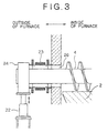
- As the discharger used in prior art 1 described above, a discharge screw having a schematic structure shown in Fig. 3 is generally employed.
- That is, as shown in Fig. 3, a through-
hole 26 is provided on the side wall of a moving-hearth furnace, and ascrew axis 4 of the discharge screw is extended to the outside of the furnace and is supported by a screw axis bearing 24 arranged outside of the furnace. Thescrew axis 4 is revolved by a drive device fordischarger 28 arranged outside of the furnace through a chain or the like. Since the discharge screw must be moved vertically during operation, anelevating device 22 for moving the screw bearing 24 vertically is provided, and anexpansion joint 23, functioning as a gas-sealing means, which is made of metal is also provided so as to prevent air from entering the furnace through the gap between the through-hole 26 and thescrew axis 4 and to prevent furnace gas from leaking out of the furnace. - However, in the
metal expansion joint 23 as shown in Fig. 3, in general, since the amount of expansion in a direction perpendicular to the axial direction is smaller than the amount of expansion in the axial direction, it is difficult to secure the amount of vertical movement of thescrew axis 4 required for the operation. Furthermore, as vertical movement is repeated, theexpansion joint 23 is subjected to repeated elastic deformation in the direction perpendicular to the axial direction, and damage, such as cracks, due to metal fatigue easily occurs. When such damage occurs, in order to replace theexpansion joint 23, the screw bearing 24 section must be disassembled by halting the operation, and thus the maintenance work is troublesome. - Although the case in which reduced iron agglomerates are produced using iron oxide agglomerates containing the carbonaceous material as raw materials by the rotary hearth furnace has been described above, even when raw materials including nonferrous metal oxides, such as nickel oxide, chromium oxide, and cobalt oxide, instead of iron oxides, are used as raw materials, it is possible to produce reduced metal by metallizing these oxides. However, in such a case, since a metal plate similar to the iron plate described above is also formed on the surface of the hearth, the formation of the metal plate must be prevented, thus giving rise to the same problems as those described above.
- Accordingly, the present invention seeks to provide a moving-hearth furnace for producing reduced metal having a means for preventing a metal plate from being formed other than moving a discharger (discharge screw) vertically, so that the maintenance work can be significantly reduced, and to provide a method for operating the same.
- In the present invention, a moving-hearth heating furnace includes a moving hearth which moves with a metal oxide-containing material being placed thereon, a heating furnace for heating the metal oxide-containing material to produce a heat-treated material while the moving hearth is moving in the heating furnace, and a discharger for discharging the heat-treated material from the heating furnace, wherein the moving hearth is movable vertically.
- Further, in the present invention, the moving-hearth heating furnace includes an elevating device for moving the moving hearth vertically, the elevating device being provided on a supporting section for supporting the moving hearth.
- The moving-hearth heating furnace can further comprise a seal plate provided around the entire lower section of the moving hearth and a water-sealing trough fixed on a side wall of the heating furnace, wherein the length of the seal plate and the depth and fixing position of the water-sealing trough are determined so that the lower end of the seal plate is kept being immersed in water in the water-sealing trough when the moving hearth is moved upward to the upper limit.
- The moving-hearth heating furnace can further comprise a columnar partition provided on the moving hearth and a roof having a recess, wherein the top of the columnar partition is inserted into the recess and the height of the columnar partition and the depth of the recess are determined so that the top of the columnar partition does not come out of the recess when the moving hearth is moved downward to the lower limit.
- In the present invention, a method for making reduced metal agglomerates includes the steps of feeding metal oxide agglomerates containing a carbonaceous material onto a moving hearth which moves in a heating furnace, heating and reducing the metal oxide agglomerates to produce reduced metal agglomerates while the moving hearth is moving in the heating furnace, and discharging the reduced metal agglomerates from the heating furnace by a discharger provided above and in close proximity to the moving hearth in the heating furnace. The moving hearth is continuously or intermittently moved vertically depending on the thickness of a metal oxide layer formed by the deposition of powder of the metal oxide agglomerates mixed into the heating furnace together with the metal oxide agglomerates so that a gap is provided between the surface of the metal oxide layer and the discharger during operation.
- In the method for making reduced metal agglomerates, the rate of moving the moving hearth downward continuously or the amount of moving the moving hearth downward intermittently can be adjusted depending on the amount of powder of the iron oxide agglomerates entering the heating furnace
- In the method for making reduced metal agglomerates, the rate of moving said moving hearth downward can be adjusted so that a gap corresponding to three-fourths or less of the average diameter of the agglomerates is provided between the edge of a blade of a discharge screw of the discharger and the surface of the moving hearth or the iron oxide layer.
- In accordance with the present invention, since metallic powder generated by the reduction of powder of metal oxide agglomerates is not compressed into the surface of the moving hearth, the formation of a metal plate can be prevented. In addition, the maintenance workload for the sealing mechanism of the discharger can be significantly reduced, continuous operation is enabled for a longer period of time, and reduced metal having a high metallization rate can be obtained stably.
- The above and other aspects of the present invention will now be described in further detail, by way of example only, with reference to the accompanying drawings, in which:
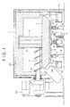
- Fig. 1 is a sectional view of a rotary hearth furnace according to an embodiment of the present invention.
- Fig. 2 is a schematic diagram showing an elevating device provided on a supporting section of a rotary hearth of the rotary hearth furnace according to the embodiment of the present invention.
- Fig. 3 is a sectional view which schematically shows the structure of a discharge screw used in Prior Art 1.
-
- Figs. 1 and 2 show an embodiment of the present invention in the case in which reduced iron, as the reduced metal, is produced using a rotary hearth furnace, as the moving-hearth heating furnace, and using iron oxide agglomerates as the metal oxide agglomerates.
- As shown in Fig. 1, the rotary hearth furnace includes a furnace shell 1 and a
rotary hearth 2. The furnace shell 1 does not have the commonly used annular structure including an outer wall, an inner wall, and a roof linking them, as in the conventional method, but has a cap-shaped structure including only an outer wall and a roof, without an inner wall. Therotary hearth 2 does not have the commonly used doughnut-shaped structure in which the central section is an empty space, but has a disk-shaped structure having acolumnar partition 3 provided in the center and extending upward. The reason for employing such a structure is that, as will be described above, a gas sealing means for an inner wall section is not required because an inner wall is eliminated, thus significantly reducing the maintenance work. - A
metallic support frame 5 is disposed in contact with the lower surface of therotary hearth 2 in order to support the weight of therotary hearth 2 composed of a refractory material, and so on. Anannular rail 6, which is concentric with the axis of therotary hearth 2, is fixed upside down on the lower surface of thesupport frame 5. A plurality ofsupport rollers 7 which support therail 6 from below are placed on the same circumference as that of therail 6. Eachsupport roller 7 is provided with anelevating device 8. A mechanically or electrically synchronizing mechanism is provided between all the providedelevating devices 8. By operating theelevating devices 8, the plurality ofsupport rollers 7 are moved vertically at the same time, and therotary hearth 2 can be elevated via therail 6 supported by thesupport rollers 7 and thesupport frame 5 while the surface of therotary hearth 2 is kept horizontal. - Reference numeral 9 represents a rotating axis for rotating the
rotary hearth 2 horizontally. The rotating axis 9 is rotated by adriving device 17. As shown in Fig. 2 in detail, the rotating axis 9 includes aninternal cylinder 10 of the rotating axis and anexternal cylinder 11 of the rotating axis. Theinternal cylinder 10 of the rotating axis is joined to the lower surface of thesupport frame 5 so as to correspond to the axis of rotation of therotary hearth 2. Theexternal cylinder 11 is rotatably inserted into asupport device 13 fixed on the ground (floor) withradial bearings 14 andthrust bearings 15 therebetween. Theinternal cylinder 10 and theexternal cylinder 11 are connected to each other by a spline mechanism, and theinternal cylinder 10 moves smoothly in relation to theexternal cylinder 11. Therefore, since theinternal cylinder 10 moves vertically and contracts in conjunction with the vertical movement by the elevatingdevices 8 provided on theindividual support rollers 7, therotary hearth 2 is not prevented from being moved vertically. Asprocket 12 is mounted on theexternal cylinder 11. Thesprocket 12 is connected to adriving device 17 including a motor and a speed reducer via achain 16. Therefore, by using the rotating axis 9 and the drivingdevice 17, it is possible to move the rotary hearth vertically while rotating the rotary hearth at a desired rotational speed. - A
seal plate 18 is provided around the entire lower section of therotary hearth 2 like a headband. As therotary hearth 2 is moved vertically, theseal plate 18 is also moved vertically. Theseal plate 18 displays a gas-sealing function in a state in which at least the lower end thereof is immersed in water filled in a water-sealingtrough 19. The water-sealingtrough 19 is usually fixed on the side wall of the furnace, etc. The length of theseal plate 18 and the depth and fixing position of the water-sealing trough are determined so that the lower end of theseal plate 18 is kept being immersed in water in order to ensure water sealing suitable for the furnace pressure even when therotary hearth 2 is moved upward to the upper limit and so that the lower end of theseal plate 18 does not hit the bottom of the water-sealingtrough 19 even when therotary hearth 2 is moved downward to the lower limit. - As the
rotary hearth 2 is moved vertically, thecolumnar partition 3 provided on therotary hearth 2 is also moved vertically- The top of thecolumnar partition 3 is inserted into arecess 21 which is provided in the center of theroof 20 of the furnace shell 1. The height of thecolumnar partition 3 and the depth of therecess 21 are determined so that the top of thecolumnar partition 3 does not come out of therecess 21 even when therotary hearth 2 is moved downward to the lower limit and so that the top of thecolumnar partition 3 does not hit the bottom of therecess 21 even when therotary hearth 2 is moved upward to the upper limit. Additionally, the internal diameter of therecess 21 is slightly larger than the external diameter of thecolumnar partition 3 so that the rotation and vertical movement of thecolumnar partition 3 are not prevented and a large amount of furnace gas does not flow into therecess 21. By using such a combination of thecolumnar partition 3 and therecess 21, it is possible to direct the gas flow in the reduction furnace in the moving direction (or in a direction opposite to the moving direction) of the agglomerates, the same as the case when a furnace shell 1 provided with an inner wall, which is a commonly used structure in the conventional method, is used, and it is also possible to maintain high energy efficiency. Additionally, a gas-sealing means, which is required for the inner wall section in the conventional method, is not required. By eliminating the gas-sealing means, the maintenance work is not required in the center of the furnace, and thus the maintenance workload is significantly reduced. - By using the rotary hearth furnace 1 described above, since only the
rotary hearth 2 is moved vertically and the relative position between the furnace shell 1 and ascrew axis 4 is not changed, a sealing mechanism having a simple structure can be employed between thescrew axis 4 and a screw axis through-hole 24. For example, as shown in Fig. 1, by inserting a gland packing 27 into a gap between thescrew axis 4 and the screw axis through-hole 24, thescrew axis 4 is allowed to slide horizontally and gas sealing can be performed without fail. The gland packing can also be replaced easily, and thus the maintenance workload is significantly reduced. - By using the rotary hearth furnace described above, when the
rotary hearth 2 is continuously or intermittently moved downward, depending on the thickness of a metal oxide layer formed on therotary hearth 2 by the deposition of powder of metal oxide agglomerates mixed into the furnace together with the metal oxide agglomerates, so that a gap is provided between the surface of the metal oxide layer and the edge of the blade of thedischarge screw 4 during operation, the powder of agglomerates is not compressed into the surface of therotary hearth 2 by the edge of the blade of thedischarge screw 4, and thus it is possible to prevent an iron plate from being formed on therotary hearth 2. - Alternatively, instead of providing a gap between the surface of the iron oxide layer and the edge of the blade of the
discharge screw 4, even if the edge of the blade of the discharge screw is in contact with powder of iron oxide agglomerates further deposited on the surface of the iron oxide layer or powder of metallic iron produced by the reduction of the powder during operation, since therotary hearth 2 is moved downward, the powder of the agglomerates and the powder of metallic iron are compressed into the porous iron oxide layer sequentially and only the thickness of the iron oxide layer is increased. Therefore, it is possible to continue operation without forming an iron plate. - The rate of descending when the
rotary hearth 2 is moved downward continuously and the amount of descending when therotary hearth 2 is moved downward intermittently may be adjusted depending on the amount of powder of the iron oxide agglomerates (hereinafter, simply referred to as "agglomerates") entering the reduction furnace. In such a case, the mass of the powder of the agglomerates entering the furnace together with the iron oxide agglomerates per unit time is determined based on the amount of the iron oxide agglomerates charged and the rate of occurrence of powder of the agglomerates. The mass of the metallic iron powder obtained by reduction is determined based on the mass of the powder of the agglomerates from the past operating performance. The mass of the metallic iron powder is converted into a volume A based on the bulk density of the metallic iron powder. On the other hand, the product of the amount of descending per unit time of therotary hearth 2 and the area of the hearth is defined as a spatial volume B. Therotary hearth 2 is moved downward within the unit time so that the ratio A/B is 50 or less. With respect to the mixing rate of the powder of the agglomerates, the rate obtained from the past operating performance may be used. - If the ratio A/B exceeds 50, the gap between the edge of the blade of the
discharge screw 4 and the surface of therotary hearth 2 is decreased, and when an iron oxide layer is formed, the iron oxide layer is easily brought into contact with the edge of the blade of thedischarge screw 4, and thereby the powder of the agglomerates is strongly compressed into the iron oxide layer. As a result, an iron plate is easily formed on the iron oxide layer. Furthermore, in order to prevent the contact between the iron oxide layer formed on the surface of the movinghearth 2 and the edge of the blade of thedischarge screw 4 more reliably, the ratio A/B is preferably 20 or less. - The rate of descending (or amount of descending) of the
rotary hearth 2 may be adjusted so that a gap corresponding to three-fourths or less of the average diameter of the agglomerates is provided between the edge of the blade of thedischarge screw 4 and the surface of therotary hearth 2 or the iron oxide layer. In such a way, it is also possible to prevent the powder of the agglomerates being compressed into the surface of the moving hearth or the iron oxide layer by the edge of the blade of thedischarge screw 4, and thus the formation of an iron plate can be prevented. Herein, if the gap between the edge of the blade of thedischarge screw 4 and the surface of the movinghearth 2 or the iron oxide layer is three-fourths or more of the average diameter of the agglomerates, it is not possible to discharge reduced iron by thedischarge screw 4. The gap sufficient for passing the powder of the agglomerates is acceptable. - As described above, by adjusting the gap between the edge of the blade of the
discharge screw 4 and the surface of the iron oxide layer depending on the amount of powder of the agglomerates mixed, the metallic iron powder is not compressed into the iron oxide layer to form an iron plate, and only an iron oxide layer is formed. - However, if the operation is continued while providing a gap between the edge of the blade of the
discharge screw 4 and the surface of the movinghearth 2 so as not to compress the powder of the agglomerates into the surface of the movinghearth 2, the powder of the agglomerates mixed starts to form an iron oxide layer on the surface of therotary hearth 2 and the thickness thereof increases, which may obstruct the operation. However, this iron oxide layer is porous because it is not strongly pressed by the edge of the blade of thedischarge screw 4. Therefore, it is possible to scrape the iron oxide layer off easily with a cutter or the like. Additionally, since the iron oxide layer is porous, even when the iron oxide layer is separated from the surface of the movinghearth 2, the layer is separated in small lumps. Therefore, the separated iron oxide is not wound around thedischarge screw 4 or does not cause clogging of the discharge port for reduced iron. - By scraping off the porous iron oxide layer formed on the surface of the
rotary hearth 2 regularly, the surface of therotary hearth 2 can be renewed regularly. In such a way, it is possible to perform continuous operation without repairing therotary hearth 2. - Additionally, by scraping the iron oxide layer 9 off regularly with a cutter and also by chipping the surface of the moving
hearth 2 within the allowable range, it is possible to remove depressions and cracks occurring on the surface of the movinghearth 2, and the maintenance period of the movinghearth 2 can be delayed. Furthermore, it is possible to obtain reduced iron of stable quality. Herein, "regularly" means at the time when continuous operation is obstructed, which depends on the scale of facilities, and operational conditions. - In this embodiment, with respect to the rotary hearth furnace, the furnace shell 1 is cap-shaped, the
rotary hearth 2 is disk-shaped, and thecolumnar partition 3 is provided in the center thereof. However, the present invention is not necessarily limited to this, and the furnace shell may be annular and the rotary hearth may be doughnut-shaped, in the same manner as that of the conventional method. - In this embodiment, the
rail 6 is fixed upside down on the lower surface of therotary hearth 2, and therollers 7 provided with the elevatingdevices 8 are provided on the ground (floor) side. However, the present invention is not necessarily limited to this, and a method may be used in which rollers or wheels are fixed on the lower surface of the rotary hearth, a rail is arranged on the ground (floor) side, and a plurality of elevating devices are provided on the lower surface of the rail so that the entire rail is moved vertically. - In this embodiment, the discharge screw axis and the through-hole are sealed with a gland packing. However, the present invention is not limited to this, and an expansion joint similar to that in Prior Art 1 may be used. In such a case, since the discharge screw axis does not move vertically and only expands horizontally, the fatigue life of the expansion joint is sufficiently long, and the maintenance workload due to the replacement of the expansion joint can be reduced.
Claims (7)
- A moving-hearth heating furnace comprising:wherein said moving hearth is movable vertically.a moving hearth moving with a metal oxide-containing material placed on said moving hearth;a heating furnace for heating the metal oxide-containing material to produce a heat-treated material while said moving hearth is moving in said heating furnace; anda discharger for discharging the heat-treated material from said heating furnace,
- The moving-hearth heating furnace according to Claim 1, further comprising an elevating device for moving said moving hearth vertically, said elevating device being provided on a supporting section for supporting said moving hearth.
- The moving-hearth heating furnace according to Claim 1 or Claim 2 further comprising a seal plate provided around said entire lower section of said moving hearth and a water-sealing trough fixed on a side wall of said heating furnace, wherein the length of said seal plate and the depth and fixing position of said water-sealing trough are determined so that the lower end of said seal plate is kept being immersed in water in said water-sealing trough when said moving hearth is moved upward to the upper limit.
- The moving-hearth heating furnace according to Claim 1, 2 or 3 further comprising a columnar partition provided on said moving hearth and a roof having a recess, wherein the top of said columnar partition is inserted into said recess and the height of said columnar partition and the depth of said recess are determined so that the top of said columnar partition does not come out of said recess when said moving hearth is moved downward to the lower limit.
- A method for making reduced metal agglomerates using a moving-hearth heating furnace which comprises a heating furnace, a moving hearth moving in said heating furnace, and a discharger for discharging a material from said heating furnace provided above and in close proximity to said moving hearth, said method comprising the steps of:wherein said moving hearth is continuously or intermittently moved vertically depending on the thickness of a metal oxide layer formed by the deposition of powder of the metal oxide agglomerates mixed into said heating furnace together with the metal oxide agglomerates so that a gap is provided between the surface of the metal oxide layer and said discharger during operation.feeding metal oxide agglomerates containing a carbonaceous material onto said moving hearth;heating and reducing the metal oxide agglomerates to produce reduced metal agglomerates while said moving hearth is moving in said heating furnace; anddischarging the reduced metal agglomerates from said heating furnace by said discharger,
- The method for making reduced metal agglomerates according to Claim 5, wherein the rate of moving said moving hearth downward continuously or the amount of moving said moving hearth downward intermittently is adjusted depending on the amount of powder of the metal oxide agglomerates entering said heating furnace
- The method for making reduced metal agglomerates according to Claim 5, wherein the rate of moving said moving hearth downward is adjusted so that a gap corresponding to three-fourths or less of the average diameter of the agglomerates is provided between the edge of a blade of a discharge screw of said discharger and the surface of said moving hearth or the iron oxide layer.
Applications Claiming Priority (2)
| Application Number | Priority Date | Filing Date | Title |
|---|---|---|---|
| JP2001216862A JP2003028575A (en) | 2001-07-17 | 2001-07-17 | Shifting floor type heating furnace and method for manufacturing reduced metal briquette |
| JP2001216862 | 2001-07-17 |
Publications (2)
| Publication Number | Publication Date |
|---|---|
| EP1277844A1 true EP1277844A1 (en) | 2003-01-22 |
| EP1277844B1 EP1277844B1 (en) | 2006-10-25 |
Family
ID=19051279
Family Applications (1)
| Application Number | Title | Priority Date | Filing Date |
|---|---|---|---|
| EP02254726A Expired - Lifetime EP1277844B1 (en) | 2001-07-17 | 2002-07-05 | Moving-hearth heating furnace and method for making reduced metal agglomerates |
Country Status (7)
| Country | Link |
|---|---|
| US (1) | US6790255B2 (en) |
| EP (1) | EP1277844B1 (en) |
| JP (1) | JP2003028575A (en) |
| AT (1) | ATE343647T1 (en) |
| CA (1) | CA2392407A1 (en) |
| DE (1) | DE60215588T2 (en) |
| TW (1) | TW544465B (en) |
Cited By (3)
| Publication number | Priority date | Publication date | Assignee | Title |
|---|---|---|---|---|
| US6942001B1 (en) * | 2003-09-04 | 2005-09-13 | Grantlin, Inc. | Magnetic sealing apparatus for portal covering |
| EP1591739A4 (en) * | 2003-02-05 | 2006-08-09 | Kobe Steel Ltd | Seal structure of solid feeding screw, and method of manufacturing reduced metal using the seal structure |
| CN102445083A (en) * | 2011-12-19 | 2012-05-09 | 青岛科技大学 | Batch feeding and discharging system and method for continuous production type vacuum atmosphere furnace |
Families Citing this family (7)
| Publication number | Priority date | Publication date | Assignee | Title |
|---|---|---|---|---|
| EP1553196B1 (en) * | 2002-10-18 | 2008-07-30 | Kabushiki Kaisha Kobe Seiko Sho | Ferronickel and process for producing raw material for ferronickel smelting |
| CA2458935A1 (en) * | 2004-03-02 | 2005-09-02 | Premier Horticulture Ltee | Oven and expansion process for perlite and vermiculite |
| AU2005313001B2 (en) * | 2004-12-07 | 2010-06-24 | Nu-Iron Technology, Llc | Method and system for producing metallic iron nuggets |
| JP4546933B2 (en) * | 2006-01-19 | 2010-09-22 | 新日本製鐵株式会社 | Reduced iron discharger for rotary furnace for reducing iron production |
| CN107011930B (en) * | 2017-05-25 | 2022-09-23 | 郑仲新 | Organic garbage treatment system |
| CN116592648B (en) * | 2023-05-31 | 2026-01-09 | 钢研晟华科技股份有限公司 | A pure hydrogen vertical shaft furnace reduction furnace bottom discharge system |
| CN117450790B (en) * | 2023-12-21 | 2024-02-27 | 包头汇泽铝业有限公司 | Aluminium bar homogeneity stove |
Citations (2)
| Publication number | Priority date | Publication date | Assignee | Title |
|---|---|---|---|---|
| US3443931A (en) * | 1965-09-10 | 1969-05-13 | Midland Ross Corp | Process for making metallized pellets from iron oxide containing material |
| JPH0213786A (en) * | 1988-06-29 | 1990-01-18 | Murata Mfg Co Ltd | Batch type calcining furnace |
Family Cites Families (16)
| Publication number | Priority date | Publication date | Assignee | Title |
|---|---|---|---|---|
| SE438730B (en) * | 1980-04-22 | 1985-04-29 | Asea Ab | PROCEDURE AND DEVICE FOR MELTING AND EVEN REFINING, AND HEATING OF SA MOLD |
| GB8925473D0 (en) * | 1989-11-10 | 1989-12-28 | Unilever Plc | Sunscreen compositions |
| JP3296974B2 (en) * | 1996-08-15 | 2002-07-02 | 株式会社神戸製鋼所 | Direct reduction method and rotary bed furnace |
| JPH10195513A (en) * | 1996-12-27 | 1998-07-28 | Kobe Steel Ltd | Production of metallic iron |
| US6149709A (en) * | 1997-09-01 | 2000-11-21 | Kabushiki Kaisha Kobe Seiko Sho | Method of making iron and steel |
| TW495552B (en) | 1997-12-18 | 2002-07-21 | Kobe Steel Ltd | Method of producing reduced iron pellets |
| JP3081581B2 (en) * | 1998-03-23 | 2000-08-28 | 株式会社神戸製鋼所 | Method of producing reduced iron agglomerates with high metallization rate |
| EP0952230A1 (en) * | 1998-03-24 | 1999-10-27 | KABUSHIKI KAISHA KOBE SEIKO SHO also known as Kobe Steel Ltd. | Method of producing reduced iron agglomerates |
| JP2997459B1 (en) * | 1998-11-04 | 2000-01-11 | 株式会社神戸製鋼所 | Method for producing reduced iron agglomerates |
| IT1303613B1 (en) * | 1998-06-18 | 2000-11-15 | Demag Italimpianti S P A Ora S | ROTARY SOLE OVEN |
| ZA995438B (en) * | 1998-08-27 | 2000-03-20 | Kobe Steel Ltd | Method for operating moving hearth reducing furnace. |
| JP3004265B1 (en) * | 1998-11-24 | 2000-01-31 | 株式会社神戸製鋼所 | Carbon material interior pellet and reduced iron production method |
| JP3404309B2 (en) * | 1999-01-18 | 2003-05-06 | 株式会社神戸製鋼所 | Method and apparatus for producing reduced iron agglomerates |
| JP3009661B1 (en) * | 1999-01-20 | 2000-02-14 | 株式会社神戸製鋼所 | Method for producing reduced iron pellets |
| CN1219891C (en) * | 1999-05-06 | 2005-09-21 | 株式会社神户制钢所 | Direct reduction method and rotary kiln hearth |
| CA2322935A1 (en) * | 1999-10-15 | 2001-04-15 | Kabushiki Kaisha Kobe Seiko Sho Also Known As Kobe Steel, Ltd. | Method and apparatus for producing reduced metal |
-
2001
- 2001-07-17 JP JP2001216862A patent/JP2003028575A/en not_active Withdrawn
-
2002
- 2002-07-04 CA CA002392407A patent/CA2392407A1/en not_active Abandoned
- 2002-07-05 AT AT02254726T patent/ATE343647T1/en not_active IP Right Cessation
- 2002-07-05 EP EP02254726A patent/EP1277844B1/en not_active Expired - Lifetime
- 2002-07-05 DE DE60215588T patent/DE60215588T2/en not_active Expired - Lifetime
- 2002-07-10 TW TW091115329A patent/TW544465B/en not_active IP Right Cessation
- 2002-07-12 US US10/193,218 patent/US6790255B2/en not_active Expired - Fee Related
Patent Citations (2)
| Publication number | Priority date | Publication date | Assignee | Title |
|---|---|---|---|---|
| US3443931A (en) * | 1965-09-10 | 1969-05-13 | Midland Ross Corp | Process for making metallized pellets from iron oxide containing material |
| JPH0213786A (en) * | 1988-06-29 | 1990-01-18 | Murata Mfg Co Ltd | Batch type calcining furnace |
Non-Patent Citations (1)
| Title |
|---|
| PATENT ABSTRACTS OF JAPAN vol. 014, no. 152 (M - 0953) 23 March 1990 (1990-03-23) * |
Cited By (5)
| Publication number | Priority date | Publication date | Assignee | Title |
|---|---|---|---|---|
| EP1591739A4 (en) * | 2003-02-05 | 2006-08-09 | Kobe Steel Ltd | Seal structure of solid feeding screw, and method of manufacturing reduced metal using the seal structure |
| US7204689B2 (en) | 2003-02-05 | 2007-04-17 | Kobe Steel, Ltd. | Seal structure of solid feeding screw, and method of manufacturing reduced metal using the seal structure |
| CN100457924C (en) * | 2003-02-05 | 2009-02-04 | 株式会社神户制钢所 | Sealing structure for solid conveying screw and method for producing reduced metal using the same |
| US6942001B1 (en) * | 2003-09-04 | 2005-09-13 | Grantlin, Inc. | Magnetic sealing apparatus for portal covering |
| CN102445083A (en) * | 2011-12-19 | 2012-05-09 | 青岛科技大学 | Batch feeding and discharging system and method for continuous production type vacuum atmosphere furnace |
Also Published As
| Publication number | Publication date |
|---|---|
| US6790255B2 (en) | 2004-09-14 |
| CA2392407A1 (en) | 2003-01-17 |
| TW544465B (en) | 2003-08-01 |
| DE60215588T2 (en) | 2007-08-30 |
| EP1277844B1 (en) | 2006-10-25 |
| DE60215588D1 (en) | 2006-12-07 |
| US20030015064A1 (en) | 2003-01-23 |
| JP2003028575A (en) | 2003-01-29 |
| ATE343647T1 (en) | 2006-11-15 |
Similar Documents
| Publication | Publication Date | Title |
|---|---|---|
| CN1170107C (en) | A method of operating a moving hearth type reduction furnace | |
| US6319302B1 (en) | Method for manufacturing reduced iron agglomerates and apparatus there for | |
| EP1277844B1 (en) | Moving-hearth heating furnace and method for making reduced metal agglomerates | |
| EP0896066A1 (en) | Method and apparatus for manufacturing reduced iron | |
| JP2972796B2 (en) | Method and apparatus for reduction annealing of iron powder | |
| JPS582356B2 (en) | Top-shaped lime kiln | |
| JP4546933B2 (en) | Reduced iron discharger for rotary furnace for reducing iron production | |
| CA1071864A (en) | Shaft furnace with bottom discharge device | |
| EP0286381B1 (en) | Apparatus and method for feeding sintering raw mix | |
| JP2001064710A (en) | Leveling method of granular raw material for reduced iron and leveling device therefor | |
| CN216011803U (en) | Blowing type sintering waste heat recovery agglomeration device | |
| CN215102011U (en) | Complete equipment for carbonization production | |
| US7655181B2 (en) | Screw conveyor of rotary hearth furnace for discharging reduced iron | |
| KR20010024881A (en) | Method for reducing iron oxides and installation therefor | |
| JP3583067B2 (en) | Discharge device of moving hearth type heat treatment furnace and method of operating the same | |
| CN2317453Y (en) | External heating rotary kiln | |
| KR100418273B1 (en) | Reduced iron discharge apparatus for rotary hearth furnace | |
| JP2000144225A (en) | Operation of movable hearth type reduction furnace | |
| JP2919493B2 (en) | Vertical furnace equipment | |
| CN222617541U (en) | Rotary bottom kiln | |
| CN113834342B (en) | A blast-type sintering waste heat recovery agglomeration device and method | |
| CN200949991Y (en) | Novel crash and discharge screen of shaft kiln | |
| JP2735839B2 (en) | Equipment for charging sintering raw materials | |
| JPH1150120A (en) | Rotating hearth maintenance method for reduced iron production | |
| JP3820677B2 (en) | Method and apparatus for charging reduced iron production raw material |
Legal Events
| Date | Code | Title | Description |
|---|---|---|---|
| PUAI | Public reference made under article 153(3) epc to a published international application that has entered the european phase |
Free format text: ORIGINAL CODE: 0009012 |
|
| AK | Designated contracting states |
Kind code of ref document: A1 Designated state(s): AT BE BG CH CY CZ DE DK EE ES FI FR GB GR IE IT LI LU MC NL PT SE SK TR |
|
| AX | Request for extension of the european patent |
Free format text: AL;LT;LV;MK;RO;SI |
|
| 17P | Request for examination filed |
Effective date: 20030623 |
|
| AKX | Designation fees paid |
Designated state(s): AT BE BG CH CY CZ DE DK EE ES FI FR GB GR IE IT LI LU MC NL PT SE SK TR |
|
| GRAP | Despatch of communication of intention to grant a patent |
Free format text: ORIGINAL CODE: EPIDOSNIGR1 |
|
| GRAS | Grant fee paid |
Free format text: ORIGINAL CODE: EPIDOSNIGR3 |
|
| GRAA | (expected) grant |
Free format text: ORIGINAL CODE: 0009210 |
|
| AK | Designated contracting states |
Kind code of ref document: B1 Designated state(s): AT BE BG CH CY CZ DE DK EE ES FI FR GB GR IE IT LI LU MC NL PT SE SK TR |
|
| PG25 | Lapsed in a contracting state [announced via postgrant information from national office to epo] |
Ref country code: LI Free format text: LAPSE BECAUSE OF FAILURE TO SUBMIT A TRANSLATION OF THE DESCRIPTION OR TO PAY THE FEE WITHIN THE PRESCRIBED TIME-LIMIT Effective date: 20061025 Ref country code: IT Free format text: LAPSE BECAUSE OF FAILURE TO SUBMIT A TRANSLATION OF THE DESCRIPTION OR TO PAY THE FEE WITHIN THE PRESCRIBED TIME-LIMIT;WARNING: LAPSES OF ITALIAN PATENTS WITH EFFECTIVE DATE BEFORE 2007 MAY HAVE OCCURRED AT ANY TIME BEFORE 2007. THE CORRECT EFFECTIVE DATE MAY BE DIFFERENT FROM THE ONE RECORDED. Effective date: 20061025 Ref country code: AT Free format text: LAPSE BECAUSE OF FAILURE TO SUBMIT A TRANSLATION OF THE DESCRIPTION OR TO PAY THE FEE WITHIN THE PRESCRIBED TIME-LIMIT Effective date: 20061025 Ref country code: SK Free format text: LAPSE BECAUSE OF FAILURE TO SUBMIT A TRANSLATION OF THE DESCRIPTION OR TO PAY THE FEE WITHIN THE PRESCRIBED TIME-LIMIT Effective date: 20061025 Ref country code: FI Free format text: LAPSE BECAUSE OF FAILURE TO SUBMIT A TRANSLATION OF THE DESCRIPTION OR TO PAY THE FEE WITHIN THE PRESCRIBED TIME-LIMIT Effective date: 20061025 Ref country code: CZ Free format text: LAPSE BECAUSE OF FAILURE TO SUBMIT A TRANSLATION OF THE DESCRIPTION OR TO PAY THE FEE WITHIN THE PRESCRIBED TIME-LIMIT Effective date: 20061025 Ref country code: NL Free format text: LAPSE BECAUSE OF FAILURE TO SUBMIT A TRANSLATION OF THE DESCRIPTION OR TO PAY THE FEE WITHIN THE PRESCRIBED TIME-LIMIT Effective date: 20061025 Ref country code: CH Free format text: LAPSE BECAUSE OF FAILURE TO SUBMIT A TRANSLATION OF THE DESCRIPTION OR TO PAY THE FEE WITHIN THE PRESCRIBED TIME-LIMIT Effective date: 20061025 |
|
| REG | Reference to a national code |
Ref country code: GB Ref legal event code: FG4D |
|
| REG | Reference to a national code |
Ref country code: CH Ref legal event code: EP |
|
| REG | Reference to a national code |
Ref country code: IE Ref legal event code: FG4D |
|
| REF | Corresponds to: |
Ref document number: 60215588 Country of ref document: DE Date of ref document: 20061207 Kind code of ref document: P |
|
| PG25 | Lapsed in a contracting state [announced via postgrant information from national office to epo] |
Ref country code: SE Free format text: LAPSE BECAUSE OF FAILURE TO SUBMIT A TRANSLATION OF THE DESCRIPTION OR TO PAY THE FEE WITHIN THE PRESCRIBED TIME-LIMIT Effective date: 20070125 Ref country code: BG Free format text: LAPSE BECAUSE OF FAILURE TO SUBMIT A TRANSLATION OF THE DESCRIPTION OR TO PAY THE FEE WITHIN THE PRESCRIBED TIME-LIMIT Effective date: 20070125 Ref country code: DK Free format text: LAPSE BECAUSE OF FAILURE TO SUBMIT A TRANSLATION OF THE DESCRIPTION OR TO PAY THE FEE WITHIN THE PRESCRIBED TIME-LIMIT Effective date: 20070125 |
|
| PG25 | Lapsed in a contracting state [announced via postgrant information from national office to epo] |
Ref country code: ES Free format text: LAPSE BECAUSE OF FAILURE TO SUBMIT A TRANSLATION OF THE DESCRIPTION OR TO PAY THE FEE WITHIN THE PRESCRIBED TIME-LIMIT Effective date: 20070205 |
|
| PG25 | Lapsed in a contracting state [announced via postgrant information from national office to epo] |
Ref country code: PT Free format text: LAPSE BECAUSE OF FAILURE TO SUBMIT A TRANSLATION OF THE DESCRIPTION OR TO PAY THE FEE WITHIN THE PRESCRIBED TIME-LIMIT Effective date: 20070326 |
|
| NLV1 | Nl: lapsed or annulled due to failure to fulfill the requirements of art. 29p and 29m of the patents act | ||
| ET | Fr: translation filed | ||
| REG | Reference to a national code |
Ref country code: CH Ref legal event code: PL |
|
| PLBE | No opposition filed within time limit |
Free format text: ORIGINAL CODE: 0009261 |
|
| STAA | Information on the status of an ep patent application or granted ep patent |
Free format text: STATUS: NO OPPOSITION FILED WITHIN TIME LIMIT |
|
| 26N | No opposition filed |
Effective date: 20070726 |
|
| GBPC | Gb: european patent ceased through non-payment of renewal fee |
Effective date: 20070705 |
|
| PG25 | Lapsed in a contracting state [announced via postgrant information from national office to epo] |
Ref country code: GR Free format text: LAPSE BECAUSE OF FAILURE TO SUBMIT A TRANSLATION OF THE DESCRIPTION OR TO PAY THE FEE WITHIN THE PRESCRIBED TIME-LIMIT Effective date: 20070126 Ref country code: MC Free format text: LAPSE BECAUSE OF NON-PAYMENT OF DUE FEES Effective date: 20070731 |
|
| PG25 | Lapsed in a contracting state [announced via postgrant information from national office to epo] |
Ref country code: GB Free format text: LAPSE BECAUSE OF NON-PAYMENT OF DUE FEES Effective date: 20070705 |
|
| PG25 | Lapsed in a contracting state [announced via postgrant information from national office to epo] |
Ref country code: IE Free format text: LAPSE BECAUSE OF NON-PAYMENT OF DUE FEES Effective date: 20070705 |
|
| PG25 | Lapsed in a contracting state [announced via postgrant information from national office to epo] |
Ref country code: EE Free format text: LAPSE BECAUSE OF FAILURE TO SUBMIT A TRANSLATION OF THE DESCRIPTION OR TO PAY THE FEE WITHIN THE PRESCRIBED TIME-LIMIT Effective date: 20061025 |
|
| PG25 | Lapsed in a contracting state [announced via postgrant information from national office to epo] |
Ref country code: LU Free format text: LAPSE BECAUSE OF NON-PAYMENT OF DUE FEES Effective date: 20070705 Ref country code: CY Free format text: LAPSE BECAUSE OF FAILURE TO SUBMIT A TRANSLATION OF THE DESCRIPTION OR TO PAY THE FEE WITHIN THE PRESCRIBED TIME-LIMIT Effective date: 20061025 |
|
| PG25 | Lapsed in a contracting state [announced via postgrant information from national office to epo] |
Ref country code: TR Free format text: LAPSE BECAUSE OF FAILURE TO SUBMIT A TRANSLATION OF THE DESCRIPTION OR TO PAY THE FEE WITHIN THE PRESCRIBED TIME-LIMIT Effective date: 20061025 |
|
| PGFP | Annual fee paid to national office [announced via postgrant information from national office to epo] |
Ref country code: DE Payment date: 20120627 Year of fee payment: 11 Ref country code: BE Payment date: 20120713 Year of fee payment: 11 Ref country code: FR Payment date: 20120719 Year of fee payment: 11 |
|
| BERE | Be: lapsed |
Owner name: K.K. KOBE SEIKO SHO (KOBE STEEL, LTD.) Effective date: 20130731 |
|
| REG | Reference to a national code |
Ref country code: DE Ref legal event code: R119 Ref document number: 60215588 Country of ref document: DE Effective date: 20140201 |
|
| REG | Reference to a national code |
Ref country code: FR Ref legal event code: ST Effective date: 20140331 |
|
| PG25 | Lapsed in a contracting state [announced via postgrant information from national office to epo] |
Ref country code: BE Free format text: LAPSE BECAUSE OF NON-PAYMENT OF DUE FEES Effective date: 20130731 Ref country code: DE Free format text: LAPSE BECAUSE OF NON-PAYMENT OF DUE FEES Effective date: 20140201 |
|
| PG25 | Lapsed in a contracting state [announced via postgrant information from national office to epo] |
Ref country code: FR Free format text: LAPSE BECAUSE OF NON-PAYMENT OF DUE FEES Effective date: 20130731 |