EP1277618A1 - Method for manufacturing anti-glare rearview mirror for vehicles - Google Patents
Method for manufacturing anti-glare rearview mirror for vehicles Download PDFInfo
- Publication number
- EP1277618A1 EP1277618A1 EP02254810A EP02254810A EP1277618A1 EP 1277618 A1 EP1277618 A1 EP 1277618A1 EP 02254810 A EP02254810 A EP 02254810A EP 02254810 A EP02254810 A EP 02254810A EP 1277618 A1 EP1277618 A1 EP 1277618A1
- Authority
- EP
- European Patent Office
- Prior art keywords
- bracket
- control lever
- mirror
- runner
- mirror housing
- Prior art date
- Legal status (The legal status is an assumption and is not a legal conclusion. Google has not performed a legal analysis and makes no representation as to the accuracy of the status listed.)
- Granted
Links
- 238000000034 method Methods 0.000 title claims abstract description 34
- 238000004519 manufacturing process Methods 0.000 title claims abstract description 23
- 230000002452 interceptive effect Effects 0.000 claims abstract 2
- 238000000465 moulding Methods 0.000 claims description 8
- 238000000926 separation method Methods 0.000 claims description 3
- 230000008859 change Effects 0.000 abstract description 4
- 230000008569 process Effects 0.000 description 12
- 241000276425 Xiphophorus maculatus Species 0.000 description 9
- 230000007306 turnover Effects 0.000 description 6
- 230000007547 defect Effects 0.000 description 4
- 238000002347 injection Methods 0.000 description 4
- 239000007924 injection Substances 0.000 description 4
- 238000002310 reflectometry Methods 0.000 description 4
- 230000007246 mechanism Effects 0.000 description 2
- 230000009471 action Effects 0.000 description 1
- 230000002950 deficient Effects 0.000 description 1
- 230000000007 visual effect Effects 0.000 description 1
Images





Classifications
-
- B—PERFORMING OPERATIONS; TRANSPORTING
- B60—VEHICLES IN GENERAL
- B60R—VEHICLES, VEHICLE FITTINGS, OR VEHICLE PARTS, NOT OTHERWISE PROVIDED FOR
- B60R1/00—Optical viewing arrangements; Real-time viewing arrangements for drivers or passengers using optical image capturing systems, e.g. cameras or video systems specially adapted for use in or on vehicles
-
- B—PERFORMING OPERATIONS; TRANSPORTING
- B60—VEHICLES IN GENERAL
- B60R—VEHICLES, VEHICLE FITTINGS, OR VEHICLE PARTS, NOT OTHERWISE PROVIDED FOR
- B60R1/00—Optical viewing arrangements; Real-time viewing arrangements for drivers or passengers using optical image capturing systems, e.g. cameras or video systems specially adapted for use in or on vehicles
- B60R1/02—Rear-view mirror arrangements
- B60R1/08—Rear-view mirror arrangements involving special optical features, e.g. avoiding blind spots, e.g. convex mirrors; Side-by-side associations of rear-view and other mirrors
- B60R1/083—Anti-glare mirrors, e.g. "day-night" mirrors
- B60R1/086—Anti-glare mirrors, e.g. "day-night" mirrors using a mirror angularly movable between a position of use and a non-glare position reflecting a dark field to the user, e.g. situated behind a transparent glass used as low-reflecting surface; Wedge-shaped mirrors
-
- B—PERFORMING OPERATIONS; TRANSPORTING
- B29—WORKING OF PLASTICS; WORKING OF SUBSTANCES IN A PLASTIC STATE IN GENERAL
- B29C—SHAPING OR JOINING OF PLASTICS; SHAPING OF MATERIAL IN A PLASTIC STATE, NOT OTHERWISE PROVIDED FOR; AFTER-TREATMENT OF THE SHAPED PRODUCTS, e.g. REPAIRING
- B29C45/00—Injection moulding, i.e. forcing the required volume of moulding material through a nozzle into a closed mould; Apparatus therefor
- B29C45/0053—Injection moulding, i.e. forcing the required volume of moulding material through a nozzle into a closed mould; Apparatus therefor combined with a final operation, e.g. shaping
- B29C45/006—Joining parts moulded in separate cavities
-
- B—PERFORMING OPERATIONS; TRANSPORTING
- B29—WORKING OF PLASTICS; WORKING OF SUBSTANCES IN A PLASTIC STATE IN GENERAL
- B29C—SHAPING OR JOINING OF PLASTICS; SHAPING OF MATERIAL IN A PLASTIC STATE, NOT OTHERWISE PROVIDED FOR; AFTER-TREATMENT OF THE SHAPED PRODUCTS, e.g. REPAIRING
- B29C45/00—Injection moulding, i.e. forcing the required volume of moulding material through a nozzle into a closed mould; Apparatus therefor
- B29C45/0053—Injection moulding, i.e. forcing the required volume of moulding material through a nozzle into a closed mould; Apparatus therefor combined with a final operation, e.g. shaping
- B29C45/006—Joining parts moulded in separate cavities
- B29C2045/0065—Joining parts moulded in separate cavities the parts being interconnected before assembling by a breaking or shearing point
Definitions
- the present invention relates to a method for manufacturing an anti-glare rearview mirror for vehicles, and more particularly, to a method for enabling an efficient assembling of an anti-glare rearview mirror for vehicles.
- An automobile is generally equipped with an anti-glare rearview mirror in the driver's compartment so that good visibility of the driver is ensured by adjusting its reflectivity even if the driver is dazzled by the light of the following car.
- Most of the anti-glare rearview mirrors have a prismatic mirror whose front face and rear face are different in reflectivity, and the rearview mirror is movable between normal position and anti-glare position by turning the prismatic mirror at a certain angle while providing the driver with the same visual field.
- An anti-glare rearview mirror consists of a mirror, a mirror housing, a rectangular bracket, a control lever, and a fixing stay.
- the bracket has a turning axle that is projecting outwardly from both ends of one side, and on the opposite side of its turning axle, the bracket has an engaging portion.
- This bracket is pivotally mounted to the mirror housing to which the prismatic mirror is fixed.
- the control lever for controlling movement of the mirror between normal and anti-glare position, consists of a stick-shaped body and a flat handle provided along and at the mid-point of the body. Also, an engaging portion is formed on one side of the stick-shaped body.
- This control lever is also pivotally mounted to the mirror housing with its engaging portion meshed with the engaging portion of the bracket.
- This rearview mirror is fixed to the vehicle body by a fixing stay that connects the bracket with the vehicle body through an aperture of the mirror housing.
- the bracket and the control lever of this anti-glare mirror are molded together in one die for reducing the cost of the die as well as saving the time for molding. Therefore, as illustrated in Fig. 6 or Fig. 7, the bracket and the control lever are molded integrally and connected by runners.
- a bracket 101 and a control lever 102 respectively have an engaging portion 101a, 102a which are to be engaged each other.
- the bracket 101 and the control lever 102 are molded together in such a manner that a sub runner 106 vertically branched from a main runner 105 connects the engaging portions 101a, 102a with said engaging portions 101a, 102a faced each other.
- the assembler cuts off the sub runner 106, brings the bracket 101 and the lever 102 close to each other while retaining the facing posture, engages the engaging portions 101a, 102a, and places the assembly into a mirror housing (Fig.6B).
- a bracket 111 and a control lever 112 respectively have an engaging portion 111a, 112a which are to be engaged each other.
- the bracket 111 and the control lever 112 are molded together in such a manner that two U-shaped runners 116 connect both ends of a turning pivot 118 of the control lever 112 and the side parts 117 of the bracket 111, with said engaging portions 111a, 112a faced each other.
- the aforementioned conventional anti-glare mirror shown in Fig. 6A has a drawback if the bracket 101 and the control lever 102 are separated at the runner 106 and assembled together into the anti-glare mirror without removing remaining parts or burrs of the runner 106.
- the drawback is that the remaining parts interfere each other upon operating the control lever 102, as illustrated in Fig. 6B, resulting defective operation of the control lever 102 or rapping sounds during the operation. Therefore, it is necessary to remove the remaining parts of the runner 106 from the bracket 101 and the control lever 102 respectively with use of nippers and the like.
- the aforementioned conventional anti-glare mirror has a similar drawback in that if the bracket 111 and the control lever 112 are separated at the runners 116 and assembled together without removing remaining parts or burrs of the runners 116, as illustrated in Fig. 7B, the remaining parts interfere each other.
- a first aspect of the present invention provides a method for manufacturing an anti-glare rearview mirror.
- the rearview mirror as a workpiece of the manufacture includes a mirror, a mirror housing for fixing the mirror, a bracket pivotally mounted to the mirror housing, and a control lever pivotally mounted to the mirror housing and engaged with the bracket.
- the relative angle between the bracket and the mirror housing is varied by a turning operation of the control lever relative to the mirror housing.
- the bracket and the control lever are molded integrally in such a manner that a runner connects the bracket and that the control lever does not interfere the movement of the bracket or the control lever if these parts are assembled to an anti-glare rearview mirror. Further, the bracket and the control lever is separated at the runner, and these parts are assembled to the mirror housing without removing a remaining part of the runner.
- the runner is formed so as not to interfere the movement of the bracket or the control lever if the bracket and the control lever are assembled into the anti-glare rearview mirror, so that a worker can separate the control lever from the bracket and assemble the bracket and the control lever into the mirror housing without cutting off the remaining part of the runner. Therefore, efficient assembly of the anti-glare rearview mirror for vehicles is achieved by leaving out the step of removing the runner. Moreover, the separated bracket and the separated control lever are available for assembling without additional process. This allows leaving out space for keeping these parts in each case and the brackets and the controls lever may be stocked in a single case and kept as an integrated body.
- the runner for connecting the bracket with the control lever is connected to inconspicuous part, for example,a certain place that avoids the surface of the engaging portion or the turning pivot to ensure its function, or avoids the surface of the control lever to keep its external view.
- a second aspect of the present invention provides a method for manufacturing an anti-glare rearview mirror.
- the rearview mirror as a workpiece of the manufacture includes a mirror, a mirror housing for fixing the mirror, a bracket pivotally mounted to the mirror housing, and a control lever pivotally mounted to the mirror housing and engaged with the bracket. So the relative angle between the bracket and the mirror housing is varied by a turning operation of the control lever relative to the mirror housing.
- the bracket and the control lever are integrally connected by a runner in such a manner that engaging portions of the bracket and that of the control lever are faced each other and that a recess portion is formed in at least one of the bracket or the control lever so as not to interfere movement of the bracket or the control lever of the assembled anti-glare rearview mirror. Further, the bracket and the control lever are separated at the runner, and these parts are assembled to the mirror housing without removing a remaining part of the runner.
- the bracket and the control lever are molded integrally connected by a runner with the engaging portion of them faced each other, and at least one of the bracket or the control lever has a recess portion that prevent an interference with a remaining part of the runner.
- a third as pect of the present invention provides a method for manufacturing an anti-glare rearview mirror.
- the rearview mirror as a workpiece of the manufacture includes a mirror, a mirror housing for fixing the mirror, a bracket pivotally mounted to the mirror housing, and a control lever pivotally mounted to the mirror housing and engaged with the bracket. So the relative angle between the bracket and the mirror housing is varied by a turning operation of the control lever relative to the mirror housing.
- the bracket and the control lever are integrally connected by a runner in such a manner that engaging portions of the bracket and that of the control lever are faced each other.
- bracket and the control lever are separated at the runner and these parts are engaged at the engaging portions without removing a remaining part of the runner with the control lever shifted along a direction of its turning axis with respect to the bracket. Finally the bracket and the control lever are assembled to the mirror housing.
- Shifting the control lever relative to the bracket in the direction of its turning axis in this manner prevents an interference of these parts with the runner, so that a worker can leave out removing process of the runners.
- the runner may have a weak section for facilitating a handwork separation of said control lever from said bracket.
- This weak section allows a worker to assemble the bracket and the control lever into a mirror housing through an operation of holding the integrally-molded bracket and lever in each hand and of separating them with a twisting action and the like, while the worker needs no turning operation of these parts. In this way, the assembly process of anti-glare rearview mirror for vehicles becomes more efficient.
- Fig. 1 illustrates a perspective view of an anti-glare rearview mirror after a bracket and a control lever has assembled to a mirror housing
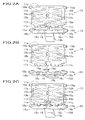
- Fig. 2A illustrates a perspective view of the bracket and the control lever molded integrally according to the first embodiment of the invention
- Fig. 2B illustrates a perspective view of the bracket and the control lever separated from each other according to the first embodiment of the invention
- Fig. 2C illustrates a perspective view of the bracket and the control lever assembled to the mirror housing according to the first embodiment of the invention.
- an anti-glare rearview mirror for vehicles with respect to the first embodiment of a method for manufacturing the mirror comprises a mirror 4, a mirror housing 5, a rectangular platy bracket 10, and a control lever 15 for controlling the movement of the rearview mirror between a normal position and an anti-glare position.
- the bracket 10 is pivotally mounted to the mirror housing 5 to turn around a bracket-turning pivot 10a.
- This bracket 10 is fixed to a vehicle body by a fixing stay 6.
- the control lever 15 is rotatably mounted on the mirror housing 5 thereby enabling the control lever 15 to turn around a lever-turning pivot 15a.
- a side of the bracket 10 is meshed with a side of the control lever 15, so a turning operation of the control lever 15 turns the bracket 10 and varies the relative angle between the mirror housing 5 and the bracket 10.
- the mirror 4 is a prismatic mirror having different reflectivity between its front and rear face, the reflectivity of the rearview mirror changes in accordance with the change in the above relative angle.
- the bracket 10 and the control lever 15 are molded together in one die by one-shot injection and are connected by a runner 18 for reducing the cost of the die as well as saving time for molding.
- the bracket 10 comprises a rectangular platy bracket body 10A and the bracket-turning pivot 10a projecting outwardly from both ends of upper side 11a in Fig. 2A.
- the bracket-turning pivot 10a is pivotally mounted to a support hole 5a of the mirror housing 5 as shown in Fig. 1, so the bracket 10 is rotatable relative to the mirror housing 5 as a result.
- the bracket 10 is formed an engaging portion 11c that meshes with the control lever 15 by uneven faces and that is arranged on a lower side away from and opposite to the upper side 11a.
- the engaging portion 11c is divided right and left in two by forming a rectangular recess 11d at the mid-point of the lower side.
- the bracket body 10A also has a spherical recess 10b at the center thereof, and a spherical part, which fits to the spherical recess 10b, is formed at the end of the fixing stay 6 while the fixing stay 6 is fixed to the vehicle body. Fitting the spherical part to the spherical recess 10b allows the mirror housing 5 to turn over freely while the mirror housing 5 is fit to the vehicle body.
- the bracket body 10A also comprises ribs 10c... all around the edge of the bracket's face and between its four corners and the spherical recess 10b in order to reinforce itself.
- the control lever 15 comprises the lever-turning pivots 15a projecting from the both ends of and along a lever body 15A having polygonal section and stick shape.
- the lever-turning pivot 15a is pivotally mounted to the support hole 5b of the mirror housing 5, so the control lever 15 is rotatable relative to the mirror housing 5 as a result.
- the control lever 15 also comprises an engaging portion 16c on the upper side of the lever body 15A in Fig. 2A.
- the engaging portion 16c meshes with the engaging portion 11c of the bracket 10 in order to transmit the motion of the control lever 15 to the bracket 10, and thereby enables the bracket 10 to turn around the bracket-turning pivot 10a.
- the engaging portion 16c is divided right and left in two by forming a projected T-shaped runner 18 at the mid-point of the engaging portion 16c.
- the lever body 15A also comprises a rectangular platy handle 15b at the mid-point of the opposite side and along the lever body 15A.
- bracket 10 and control lever 15 are molded integrally connected by the runner 18 with the engaging portion 11c and the engaging portion 16c faced each other.
- the runner 18 extends from the mid-point of the engaging portion 16c toward the recess 11d, branches right and left inside the recess 11d, and connects to the bracket 10 to form T-shape.
- the branched parts are partly narrow to make a weak section 18a that is weaker than general section of the branch.
- This weak section 18a enables an easy handwork separation of the control lever 15 from the bracket 10 by twisting the control lever 15 against the bracket 10.
- the depth and width of the recess 11d is respectively deeper and wider than the length and width of the runner 18 toward the recess 11d, thus there is no interference between the runner 18 and the recess 11d when they are assembled into a rearview mirror.
- a rearview mirror is manufactured by using the bracket 10 and the control lever 15 as mentioned above through following processes.
- the bracket 10 and the control lever 15 are molded integrally connected with the runner 18.
- an assembler holds the bracket 10 and the control lever 15 in each hand and twists them to tear at the weak section 18a, then, as shown in Fig. 2B, the bracket 10 and the control lever 15 are separated as a result.
- the assembler keeps holding the bracket 10 and the control lever 15 and brings them close to each other. Then, as shown in Fig. 2C, the remained runner 18 is shifted front and back and the engaging portion 11c is meshed with the engaging portion 16c. Holding these parts meshed, the assembler fits the bracket-turning pivot 10a in the support hole 5a of the mirror housing 5, and he pushes the lever-turning pivot 15a into the support hole 5b to fit in. Then he fits the fixing stay 6 in the spherical recess 10b of the bracket 10 and, further, he fits the mirror 4 to the front edge of the mirror housing to finish assembling the rearview mirror.
- an assembler can fit the bracket 10 and the control lever 15 in the mirror housing 5 only by twisting and tearing the runner 18 without removing the remaining runner 18 or without changing his holding positions. Moreover, because the bracket 10 has a recess 11d to be away from movable area of the runner 18 at their assembled arrangement, the runner 18 does not interfere with the bracket 10 or recess 11d without removing the remaining runner 18. As a result, there is no defect of producing so-called rapping sound. According to the present embodiment, therefore, an assembler can abbreviate a process of cutting off a runner, and can assemble an anti-glare rearview mirror more efficiently. Further, not only manpower required for cutting off the runners 18 but also space for storing brackets 10 and control levers 15 separately become unnecessary.
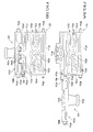
- Fig. 3A illustrates a plan view of a bracket and a control lever molded integrally according to a second embodiment of the invention
- Fig. 3B illustrates a plan view of the bracket and the control lever engaged with each other according to the second embodiment of the invention.
- parts or elements similar to those previously described regarding the first embodiment will be denoted by the same reference numbers and the description thereof will be omitted.
- a bracket 20 and a control lever 25 are molded together in one die by one-shot injection and are connected by a runner 28 for reducing the cost of the die as well as saving time for molding.
- the bracket 20 comprises a rectangular platy bracket body 20A and the bracket-turning pivot 20a projecting outwardly from both ends of upper side 21a in Fig. 3A.
- the bracket-turning pivot 20a is pivotally mounted to a support hole 5a of the mirror housing 5 as shown in Fig. 1, so the bracket 20 is rotatable relative to the mirror housing 5 as a result.
- the lower side of the bracket 20 opposite to and away from the upper side 21a is provided with an uneven-faced engaging portion 21c extending along half the length of the lower side at its mid-point, and meshable with the control lever 25.
- the bracket body 20A also has a spherical recess 20b at the center, and a spherical part, which fits to the spherical recess 20b, is formed at the end of the fixing stay 6 while the fixing stay 6 (not shown) is fixed to the vehicle body. Fitting the spherical part to the spherical recess 20b allows the mirror housing 5 to turn over freely while the mirror housing is fit to the vehicle body.
- the bracket body 20A also comprises ribs 20c... all around the edge of the bracket's face and between its four corners and the spherical recess 20b in order to reinforce itself.
- One end of the lower side of the bracket 20 is notched rectangularly and a wiry runner 28 extends sidewardly from the side face of the notch.
- the control lever 25 comprises the lever-turning pivots 25a projecting from the both end faces 26b and along a lever body 25A having polygonal section and stick shape.
- the lever-turning pivot 25a is pivotally mounted to the support hole 5b of the mirror housing 5, so the control lever 25 is rotatable relative to the mirror housing 5 as a result.
- the control lever 25 is placed on a lateral side of the bracket 20 from which the runner 28 is extended and the end faces 26b is placed on the extension line of the runner 28 to be connected with the runner 28.
- the control lever 25 also comprises an engaging portion 26c on the upper side of the lever body 25A in Fig. 2A.
- the lower side of the lever body 25A as shown in Fig. 3A, is provided with an engaging portion 21c extending along half the length of the lower side at its mid-point, and meshable with the engaging portion 26c.
- the engaging portion 26c meshes with the engaging portion 21c of the bracket 20 in order to transmit the motion of the control lever 25 to the bracket 20, and thereby enables the bracket 20 to turn around the bracket-turning pivot 20a.
- the lever body 25A also comprises a rectangular platy handle 25b at the mid-point of the opposite side and along the lever body 25A.
- the runner 28 does not interfere a motion of the bracket 20 or of the control lever 25 when the engaging portion 21c and engaging portion 26c are meshed each other, because the runners 28, as shown in Fig. 3B, respectively project sidewardly.
- a rearview mirror is manufactured by using the bracket 20 and the control lever 25 as mentioned above through following processes.
- the bracket 20 and the control lever 25 are molded integrally connected with the runner 28. And an assembler holds the bracket 20 and the control lever 25 in each hand and draws, bends, or twists them to tear at the runner 28, and to separate them to the bracket 20 and the control lever 25.
- the assembler keeps holding the bracket 20, turn over them, and brings them close to each other, then, as shown in Fig. 3C, meshes the engaging portion 21c with the engaging portion 26c. Holding these parts meshed, the assembler fits the bracket-turning pivot 20a in the support hole 5a of the mirror housing 5, and he pushes the lever-turning pivot 25a into the support hole 5b to fit in. Then he fits the fixing stay 6 in the spherical recess 20b of the bracket 20 and, further, he fits the mirror 4 to the front edge of the mirror housing to finish assemble of the rearview mirror.
- an assembler can fit the bracket 20 and the control lever 25 in the mirror housing 5 only by twisting and tearing the runner 28 without removing the remaining runner 28 or without changing his holding positions. Moreover, because the remaining runners 28 merely protrude sidewardly from the assembled bracket 20 or control lever25, the runner 28 does not interferer a motion of bracket 20 or control lever 25 without removing the remaining runner 28. As a result, there is no defect of producing so-called rapping sound. According to the present embodiment, therefore, an assembler can abbreviate a process of cutting off a runner, and can assemble an anti-glare rearview mirror more efficiently. Further, not only manpower required for cutting off the runners 28 but also space for storing brackets 20 and control levers 25 separately become unnecessary.
- Fig. 4A illustrates a plan view of a bracket and a control lever molded integrally according to a third embodiment of the invention
- Fig. 4B illustrates a plan view of the bracket and the control lever engaged with each other according to the third embodiment of the present invention.
- parts or elements similar to those previously described regarding the first embodiment will be denoted by the same reference numbers and the description thereof will be omitted.
- a bracket 30 and a control lever 35 are molded together in one die by one-shot injection and are connected by a runner 38 for reducing the cost of the die as well as saving time for molding.
- the bracket 30 comprises a rectangular platy bracket body 30A and the bracket-turning pivot 30a projecting outwardly from both ends of upper side 31a in Fig. 4A.
- the bracket-turning pivot 30a is pivotally mounted to a support hole 5a of the mirror housing 5 as shown in Fig. 1, so the bracket 30 is rotatable relative to the mirror housing 5 as a result.
- the lower side of the bracket 30 opposite to and away from the upper side31a is provided with an uneven-faced engaging portion 21c extending half the length of the lower side at its mid-point, and meshable with the control lever 25.
- the engaging portion 31c is divided right and left in two at its mid-point by forming a rectangular recess 31b.
- the bracket body 30A also has a spherical recess 30b at the center thereof, and a spherical part, which fits to the spherical recess 30b, is formed at the end of the fixing stay 6 while the fixing stay 6 (not shown) is fixed to the vehicle body. Fitting the spherical part to the spherical recess 30b allows the mirror housing 5 to turn over freely while the mirror housing is fit to the vehicle body.
- the bracket body 30A also comprises ribs 30c... all around the edge of the bracket's face and between its four corners and the spherical recess 30b in order to reinforce itself.
- the control lever 35 comprises the lever-turning pivots 35a projecting from the both end faces 36b and along a lever body 35A having polygonal section and stick shape.
- the lever-turning pivot 35a is pivotally mounted to the support hole 5b of the mirror housing 5, so the control lever 35 is rotatable relative to the mirror housing 5 as a result.
- the lower side of the lever body 35A is provided with an engaging portion 36c that will mesh with an engaging portion 31c along the half middle of the lower side.
- the engaging portion 36c is divided right and left in two by forming a rectangular recess 36d at its mid-point.
- the engaging portion 36c meshes with the engaging portion 31c of the bracket 30 in order to transmit the motion of the control lever 35 to the bracket 30, and thereby enables the bracket 30 to turn around the bracket-turning pivot 30a.
- the lever body 35A also comprises a trapeziform platy handle 35b at the mid-point of the opposite side and along the lever body 35A.
- the bracket 30 and the control lever 35 are connected with each other by a runner 38 with their engaging portions faced each other and shifted relative to their meshing position.
- the runner 38 has thin cylindrical shape and comprises a weak section 38a having narrower section at its center than other section of the runner 38. Further, the above recess 31d and the recess 36d notched deeply enough not to interfere the movement of remained runner 38 after they are separated and assembled.
- a rearview mirror is manufactured by using the bracket 30 and the control lever 35 as mentioned above through following processes. As shown in Fig. 4A, the bracket 30 and the control lever 35 are molded integrally connected with the runner 38. And an assembler holds the bracket 30 and the control lever 35 in each hand and draw, bend, or twists them to tear at the weak section 38a, then, the bracket 30 and the control lever 35 are separated as a result.
- the assembler keeps holding the bracket 30 and the control lever 35 and brings them close to each other. Then, as shown in Fig. 4B, the remained runner 18 is shifted front and back and the engaging portion 31c is meshed with the engaging portion 36c. Holding these parts meshed, the assembler fits the bracket-turning pivot 30a in the support hole 5a of the mirror housing 5, and he pushes the lever-turning pivot 35a into the support hole 5b to fit in. Then he fits the fixing stay 6 in the spherical recess 30b of the bracket 10 and, further, he fits the mirror 4 to the front of the mirror housing to finish assemble of the rearview mirror.
- an assembler can fit the bracket 30 and the control lever 35 in the mirror housing 5 only by tearing the runner 38 by twisting or the like them with his hands without removing the remaining runner 38 or without changing his holding positions. Moreover, because the recess 31d and the recess 36d is notched deep enough not to interfere the motion of the remained runners 38 after they are separated and assembled, there is no defect of producing so-called rapping sound. According to the present embodiment, therefore, an assembler can abbreviate a process of cutting off a runner, and can assemble an anti-glare rearview mirror more efficiently. Further, not only manpower required for cutting off the runners 38 but also space for storing brackets 30 and control levers 35 separately become unnecessary.
- Fig. 5A illustrates a plan view of a bracket and a control lever molded integrally according to a fourth embodiment of the invention
- Fig. 5B illustrates a plan view of the bracket and the control lever engaged with each other according to the fourth embodiment of the invention.
- parts or elements similar to those previously described regarding the first embodiment will be denoted by the same reference numbers and the description thereof will be omitted.
- a bracket 40 and a control lever 45 are molded together in one die by one-shot injection and are connected by a runner 48 for reducing the cost of the die as well as saving time for molding.
- the bracket 40 comprises a rectangular platy bracket body 40A and the bracket-turning pivot 40a projecting outwardly from both ends of upper side 41a in Fig. 5A.
- the bracket-turning pivot 40a is pivotally mounted to a support hole 5a of the mirror housing 5 as shown in Fig. 1, so the bracket 40 is rotatable relative to the mirror housing 5 as a result.
- the lower side of the bracket 40 opposite to and away from the upper side 41a is provided with an uneven-faced engaging portion 41c extending along half the length of the lower side at its mid-point, and meshable with the control lever 45.
- the bracket body 40A also has a spherical recess 40b at the center, and a spherical part, which fits to the spherical recess 40b, is formed at the end of the fixing stay 6 while the fixing stay 6 (not shown) is fixed to the vehicle body. Fitting the spherical part to the spherical recess 40b allows the mirror housing 5 to turn over freely while the mirror housing is fit to the vehicle body.
- the bracket body 40A also comprises ribs 40c... all around the edge of the bracket's face and between its four corners and the spherical recess 40b in order to reinforce itself.
- One end of the lower side of the bracket 20 is notched rectangularly to form a notch 40d and a thin wiry runner 48 extends downwardly from the undersurface of the notch.
- the control lever 45 comprises the lever-turning pivots 45a projecting from the both end faces 46b and along a lever body 45A having polygonal section and stick shape.
- the lever-turning pivot 45a is pivotally mounted to the support hole 5b of the mirror housing 5, so the control lever 45 is rotatable relative to the mirror housing 5 as a result.
- the lower side of the lever body 45A is provided with an engaging portion 41c extending half the length of the lower side at its mid-point, and meshable with the engaging portion 46c.
- the engaging portion 46c meshes with the engaging portion 41c of the bracket 40 in order to transmit the motion of the control lever 45 to the bracket 40, and thereby enables the bracket 40 to turn around the bracket-turning pivot 40a.
- the lever body 45A also comprises a trapezoidal platy handle 25b with a wide upper end at the mid-point of the opposite side and along the lever body 45A.
- One end face 46b of the control lever 45 is notched rectangularly to form a notch 45d.
- a wiry runner 28 extends downwardly from the undersurface of the notch 45d.
- the bracket 40 and the control lever 45 are placed side by side with their notches 40d, 45d close and they are connected by a runner 48 extended respectively from the notches 40d, 45d.
- the runner 48 connects the undersurfaces of the above notches 40d, 45.
- the runner 48 is formed in such a manner that the runner 48 does not interfere motion of the bracket 40 or the control lever when the engaging portion 41c and the engaging portion 46c are meshed with each other.
- a rearview mirror is manufactured by using the bracket 40 and the control lever 45 as mentioned above through following processes.
- the bracket 40 and the control lever 45 are molded integrally connected with the runner 48. And an assembler holds the bracket 40 and the control lever 45 in each hand and draws, bends, or twists them to tear at the runner 28, and to separate them to the bracket 40 and the control lever 45.
- the assembler keeps holding the bracket 40, turn over them, and brings them close to each other, then, as shown in Fig. 5C, meshes the engaging portion 41c with the engaging portion 46c. Holding these parts meshed, the assembler fits the bracket-turning pivot 40a in the support hole 5a of the mirror housing 5, and he pushes the lever-turning pivot 45a into the support hole 5b to fit in. Then he fits the fixing stay 6 in the spherical recess 40b of the bracket 40 and, further, he fits the mirror 4 to the front of the mirror housing to finish assemble of the rearview mirror.
- an assembler can fit the bracket 40 and the control lever 45 in the mirror housing 5 only by twisting and tearing the runner 48 without removing the remaining runner 48 or without changing his holding positions. Moreover, because the remaining runners 48 merely protrude sidewardly from the assembled bracket 40 or control lever 45, the runner 48 does not interferer a motion of bracket 40 or control lever 45 without removing the remaining runner 48. As a result, there is no defect of producing so-called rapping sound. According to the present embodiment, therefore, an assembler can abbreviate a process of cutting off a runner, and can assemble an anti-glare rearview mirror more efficiently. Further, not only manpower required for cutting off the runners 48 but also space for storing brackets 40 and control levers 45 separately become unnecessary.
- a runner for connecting a bracket and a control lever may be formed in such a manner that the runner does not interfere a motion of assembled bracket or control lever by a turning operation of the control lever.
- the runner may be provided at various places, for example, at a corner of a bracket, at an end of a turning pivot, or at a side of an engaging portion formed protruding shape.
Landscapes
- Engineering & Computer Science (AREA)
- Mechanical Engineering (AREA)
- Multimedia (AREA)
- Manufacturing & Machinery (AREA)
- Rear-View Mirror Devices That Are Mounted On The Exterior Of The Vehicle (AREA)
- Mounting And Adjusting Of Optical Elements (AREA)
Abstract
Description
- The present invention relates to a method for manufacturing an anti-glare rearview mirror for vehicles, and more particularly, to a method for enabling an efficient assembling of an anti-glare rearview mirror for vehicles.
- An automobile is generally equipped with an anti-glare rearview mirror in the driver's compartment so that good visibility of the driver is ensured by adjusting its reflectivity even if the driver is dazzled by the light of the following car. Most of the anti-glare rearview mirrors have a prismatic mirror whose front face and rear face are different in reflectivity, and the rearview mirror is movable between normal position and anti-glare position by turning the prismatic mirror at a certain angle while providing the driver with the same visual field.
- The following mechanism for turning a mirror of anti-glare rearview mirror is known as a conventional rearview mirror for vehicles. An anti-glare rearview mirror consists of a mirror, a mirror housing, a rectangular bracket, a control lever, and a fixing stay. The bracket has a turning axle that is projecting outwardly from both ends of one side, and on the opposite side of its turning axle, the bracket has an engaging portion. This bracket is pivotally mounted to the mirror housing to which the prismatic mirror is fixed. The control lever, for controlling movement of the mirror between normal and anti-glare position, consists of a stick-shaped body and a flat handle provided along and at the mid-point of the body. Also, an engaging portion is formed on one side of the stick-shaped body. This control lever is also pivotally mounted to the mirror housing with its engaging portion meshed with the engaging portion of the bracket. This rearview mirror is fixed to the vehicle body by a fixing stay that connects the bracket with the vehicle body through an aperture of the mirror housing.
- In this mechanism, turning the control lever with an operation of the handle allows the bracket to turn slightly to change a relative angle between the bracket and the mirror housing. As described above, since the bracket is fixed to the vehicle body by the fixing stay, the operation of turning the control lever does not change the position of the bracket but changes the angle of the mirror instead, so that the reflection on the prismatic mirror switches between the front and rear face of the mirror.
- The bracket and the control lever of this anti-glare mirror are molded together in one die for reducing the cost of the die as well as saving the time for molding. Therefore, as illustrated in Fig. 6 or Fig. 7, the bracket and the control lever are molded integrally and connected by runners.
- In Fig. 6A, a
bracket 101 and acontrol lever 102 respectively have anengaging portion bracket 101 and thecontrol lever 102 are molded together in such a manner that asub runner 106 vertically branched from amain runner 105 connects theengaging portions engaging portions bracket 101 and thecontrol lever 102 are assembled, the assembler cuts off thesub runner 106, brings thebracket 101 and thelever 102 close to each other while retaining the facing posture, engages theengaging portions - In Fig. 7A, a
bracket 111 and acontrol lever 112 respectively have anengaging portion bracket 111 and thecontrol lever 112 are molded together in such a manner that two U-shapedrunners 116 connect both ends of a turningpivot 118 of thecontrol lever 112 and theside parts 117 of thebracket 111, with saidengaging portions - However, the aforementioned conventional anti-glare mirror shown in Fig. 6A has a drawback if the
bracket 101 and thecontrol lever 102 are separated at therunner 106 and assembled together into the anti-glare mirror without removing remaining parts or burrs of therunner 106. The drawback is that the remaining parts interfere each other upon operating thecontrol lever 102, as illustrated in Fig. 6B, resulting defective operation of thecontrol lever 102 or rapping sounds during the operation. Therefore, it is necessary to remove the remaining parts of therunner 106 from thebracket 101 and thecontrol lever 102 respectively with use of nippers and the like. - As shown in Fig .7B, the aforementioned conventional anti-glare mirror has a similar drawback in that if the
bracket 111 and thecontrol lever 112 are separated at therunners 116 and assembled together without removing remaining parts or burrs of therunners 116, as illustrated in Fig. 7B, the remaining parts interfere each other. - Meanwhile, it is time-consuming if a worker removes all remaining parts in the assembly line during assembling operation. For this reason, the bracket and the control lever have to be separated in advance with the remaining parts of the runner removed. Therefore, an additional operation and extra stock space are required.
- Moreover, it is troublesome for the worker to pick up the bracket and the control lever from different cases and assemble them.
- It would be desirable to be able to provide a method for manufacturing an anti-glare rearview mirror without requiring removal of runners and so facilitates efficient assembly.
- A first aspect of the present invention provides a method for manufacturing an anti-glare rearview mirror. The rearview mirror as a workpiece of the manufacture includes a mirror, a mirror housing for fixing the mirror, a bracket pivotally mounted to the mirror housing, and a control lever pivotally mounted to the mirror housing and engaged with the bracket. The relative angle between the bracket and the mirror housing is varied by a turning operation of the control lever relative to the mirror housing. In manufacturing this rearview mirror, the bracket and the control lever are molded integrally in such a manner that a runner connects the bracket and that the control lever does not interfere the movement of the bracket or the control lever if these parts are assembled to an anti-glare rearview mirror. Further, the bracket and the control lever is separated at the runner, and these parts are assembled to the mirror housing without removing a remaining part of the runner.
- According to this method, the runner is formed so as not to interfere the movement of the bracket or the control lever if the bracket and the control lever are assembled into the anti-glare rearview mirror, so that a worker can separate the control lever from the bracket and assemble the bracket and the control lever into the mirror housing without cutting off the remaining part of the runner. Therefore, efficient assembly of the anti-glare rearview mirror for vehicles is achieved by leaving out the step of removing the runner. Moreover, the separated bracket and the separated control lever are available for assembling without additional process. This allows leaving out space for keeping these parts in each case and the brackets and the controls lever may be stocked in a single case and kept as an integrated body.
- Meanwhile, it is preferable that the runner for connecting the bracket with the control lever is connected to inconspicuous part, for example,a certain place that avoids the surface of the engaging portion or the turning pivot to ensure its function, or avoids the surface of the control lever to keep its external view.
- A second aspect of the present invention provides a method for manufacturing an anti-glare rearview mirror. The rearview mirror as a workpiece of the manufacture includes a mirror, a mirror housing for fixing the mirror, a bracket pivotally mounted to the mirror housing, and a control lever pivotally mounted to the mirror housing and engaged with the bracket. So the relative angle between the bracket and the mirror housing is varied by a turning operation of the control lever relative to the mirror housing. In manufacturing this rearview mirror, the bracket and the control lever are integrally connected by a runner in such a manner that engaging portions of the bracket and that of the control lever are faced each other and that a recess portion is formed in at least one of the bracket or the control lever so as not to interfere movement of the bracket or the control lever of the assembled anti-glare rearview mirror. Further, the bracket and the control lever are separated at the runner, and these parts are assembled to the mirror housing without removing a remaining part of the runner.
- According to this method, the bracket and the control lever are molded integrally connected by a runner with the engaging portion of them faced each other, and at least one of the bracket or the control lever has a recess portion that prevent an interference with a remaining part of the runner. An assembler, therefore, can separate and mesh the bracket and the lever without additional process. The worker can also assemble them to the mirror housing without turning the aspect of the lever because the engaging portion of the bracket and that of the lever have already faced each other.
- A third as pect of the present invention provides a method for manufacturing an anti-glare rearview mirror. The rearview mirror as a workpiece of the manufacture includes a mirror, a mirror housing for fixing the mirror, a bracket pivotally mounted to the mirror housing, and a control lever pivotally mounted to the mirror housing and engaged with the bracket. So the relative angle between the bracket and the mirror housing is varied by a turning operation of the control lever relative to the mirror housing. In manufacturing this rearview mirror, the bracket and the control lever are integrally connected by a runner in such a manner that engaging portions of the bracket and that of the control lever are faced each other. Further, the bracket and the control lever are separated at the runner and these parts are engaged at the engaging portions without removing a remaining part of the runner with the control lever shifted along a direction of its turning axis with respect to the bracket. Finally the bracket and the control lever are assembled to the mirror housing.
- Shifting the control lever relative to the bracket in the direction of its turning axis in this manner prevents an interference of these parts with the runner, so that a worker can leave out removing process of the runners.
- In all aspects of the present invention the runner may have a weak section for facilitating a handwork separation of said control lever from said bracket.
- This weak section allows a worker to assemble the bracket and the control lever into a mirror housing through an operation of holding the integrally-molded bracket and lever in each hand and of separating them with a twisting action and the like, while the worker needs no turning operation of these parts. In this way, the assembly process of anti-glare rearview mirror for vehicles becomes more efficient.
- By way of examples only, the aspects of the invention will now be described in greater detail with reference to the accompanying drawings of which:
- Fig. 1 illustrates a perspective view of an anti-glare rearview mirror after a bracket and a control lever has assembled to a mirror housing;
- Fig. 2A illustrates a perspective view of a bracket and a control lever molded integrally according to the first embodiment of the invention;
- Fig. 2B illustrates a perspective view of the bracket and the control lever separated from each other according to the first embodiment of the invention;
- Fig. 2C illustrates a perspective view of the bracket and the control lever assembled to a mirror housing according to the first embodiment of the invention;
- Fig. 3A illustrates a plan view of the bracket and the control lever molded integrally according to the second embodiment of the invention;
- Fig. 3B illustrates a plan view of the bracket and the control lever engaged with each other according to the second embodiment of the invention;
- Fig. 4A illustrates a plan view of a bracket and a control lever molded integrally according to the third embodiment of the invention;
- Fig. 4B illustrates a plan view of the bracket and the control lever engaged with each other according to the third embodiment of the present invention;
- Fig. 5A illustrates a plan view of a bracket and a control lever molded integrally according to the fourth embodiment of the invention;
- Fig. 5B illustrates a plan view of the bracket and the control lever engaged with each other according to the fourth embodiment of the invention;
- Fig. 6A illustrates a plan view of the bracket and the control lever molded integrally according to a conventional anti-glare rearview mirror for vehicles;
- Fig. 6B illustrates a plan view of the bracket and the control lever engaged with each other according to the conventional anti-glare rearview mirror of Fig. 6A;
- Fig. 7A illustrates a plan view of a bracket and a control lever molded integrally according to another example of a conventional anti-glare rearview mirror for a vehicle; and
- Fig. 7B illustrates a plan view of the bracket and the control lever engaged with each other according to the conventional anti-glare rearview mirror of Fig. 7A.
-
- With reference to the drawings, embodiments of the present invention are thereinafter described in detail. In these drawings, Fig. 1 illustrates a perspective view of an anti-glare rearview mirror after a bracket and a control lever has assembled to a mirror housing; Fig. 2A illustrates a perspective view of the bracket and the control lever molded integrally according to the first embodiment of the invention; Fig. 2B illustrates a perspective view of the bracket and the control lever separated from each other according to the first embodiment of the invention; and Fig. 2C illustrates a perspective view of the bracket and the control lever assembled to the mirror housing according to the first embodiment of the invention.
- As illustrated in Fig. 1, an anti-glare rearview mirror for vehicles with respect to the first embodiment of a method for manufacturing the mirror comprises a
mirror 4, amirror housing 5, arectangular platy bracket 10, and acontrol lever 15 for controlling the movement of the rearview mirror between a normal position and an anti-glare position. Thebracket 10 is pivotally mounted to themirror housing 5 to turn around a bracket-turningpivot 10a. Thisbracket 10 is fixed to a vehicle body by a fixingstay 6. Thecontrol lever 15 is rotatably mounted on themirror housing 5 thereby enabling thecontrol lever 15 to turn around a lever-turningpivot 15a. A side of thebracket 10 is meshed with a side of thecontrol lever 15, so a turning operation of thecontrol lever 15 turns thebracket 10 and varies the relative angle between themirror housing 5 and thebracket 10. Because themirror 4 is a prismatic mirror having different reflectivity between its front and rear face, the reflectivity of the rearview mirror changes in accordance with the change in the above relative angle. - As illustrated in Fig. 2A, the
bracket 10 and thecontrol lever 15 are molded together in one die by one-shot injection and are connected by arunner 18 for reducing the cost of the die as well as saving time for molding. - The
bracket 10 comprises a rectangularplaty bracket body 10A and the bracket-turningpivot 10a projecting outwardly from both ends ofupper side 11a in Fig. 2A. The bracket-turningpivot 10a is pivotally mounted to asupport hole 5a of themirror housing 5 as shown in Fig. 1, so thebracket 10 is rotatable relative to themirror housing 5 as a result. - The
bracket 10 is formed an engagingportion 11c that meshes with thecontrol lever 15 by uneven faces and that is arranged on a lower side away from and opposite to theupper side 11a. The engagingportion 11c is divided right and left in two by forming arectangular recess 11d at the mid-point of the lower side. - The
bracket body 10A also has aspherical recess 10b at the center thereof, and a spherical part, which fits to thespherical recess 10b, is formed at the end of the fixingstay 6 while the fixingstay 6 is fixed to the vehicle body. Fitting the spherical part to thespherical recess 10b allows themirror housing 5 to turn over freely while themirror housing 5 is fit to the vehicle body. - The
bracket body 10A also comprisesribs 10c... all around the edge of the bracket's face and between its four corners and thespherical recess 10b in order to reinforce itself. - The
control lever 15 comprises the lever-turningpivots 15a projecting from the both ends of and along alever body 15A having polygonal section and stick shape. The lever-turningpivot 15a is pivotally mounted to thesupport hole 5b of themirror housing 5, so thecontrol lever 15 is rotatable relative to themirror housing 5 as a result. - The
control lever 15 also comprises an engagingportion 16c on the upper side of thelever body 15A in Fig. 2A. The engagingportion 16c meshes with the engagingportion 11c of thebracket 10 in order to transmit the motion of thecontrol lever 15 to thebracket 10, and thereby enables thebracket 10 to turn around the bracket-turningpivot 10a. The engagingportion 16c is divided right and left in two by forming a projected T-shapedrunner 18 at the mid-point of the engagingportion 16c. Thelever body 15A also comprises a rectangularplaty handle 15b at the mid-point of the opposite side and along thelever body 15A. - These
bracket 10 andcontrol lever 15 are molded integrally connected by therunner 18 with the engagingportion 11c and the engagingportion 16c faced each other. - The
runner 18 extends from the mid-point of the engagingportion 16c toward therecess 11d, branches right and left inside therecess 11d, and connects to thebracket 10 to form T-shape. The branched parts are partly narrow to make aweak section 18a that is weaker than general section of the branch. Thisweak section 18a enables an easy handwork separation of thecontrol lever 15 from thebracket 10 by twisting thecontrol lever 15 against thebracket 10. Besides, the depth and width of therecess 11d is respectively deeper and wider than the length and width of therunner 18 toward therecess 11d, thus there is no interference between therunner 18 and therecess 11d when they are assembled into a rearview mirror. - A rearview mirror is manufactured by using the
bracket 10 and thecontrol lever 15 as mentioned above through following processes. As shown in Fig. 2A, thebracket 10 and thecontrol lever 15 are molded integrally connected with therunner 18. And an assembler holds thebracket 10 and thecontrol lever 15 in each hand and twists them to tear at theweak section 18a, then, as shown in Fig. 2B, thebracket 10 and thecontrol lever 15 are separated as a result. - Next the assembler keeps holding the
bracket 10 and thecontrol lever 15 and brings them close to each other. Then, as shown in Fig. 2C, the remainedrunner 18 is shifted front and back and the engagingportion 11c is meshed with the engagingportion 16c. Holding these parts meshed, the assembler fits the bracket-turningpivot 10a in thesupport hole 5a of themirror housing 5, and he pushes the lever-turningpivot 15a into thesupport hole 5b to fit in. Then he fits the fixingstay 6 in thespherical recess 10b of thebracket 10 and, further, he fits themirror 4 to the front edge of the mirror housing to finish assembling the rearview mirror. - In this way, according to a method for manufacturing an anti-glare rearview mirror of the present embodiment, an assembler can fit the
bracket 10 and thecontrol lever 15 in themirror housing 5 only by twisting and tearing therunner 18 without removing the remainingrunner 18 or without changing his holding positions. Moreover, because thebracket 10 has arecess 11d to be away from movable area of therunner 18 at their assembled arrangement, therunner 18 does not interfere with thebracket 10 orrecess 11d without removing the remainingrunner 18. As a result, there is no defect of producing so-called rapping sound. According to the present embodiment, therefore, an assembler can abbreviate a process of cutting off a runner, and can assemble an anti-glare rearview mirror more efficiently. Further, not only manpower required for cutting off therunners 18 but also space for storingbrackets 10 andcontrol levers 15 separately become unnecessary. - The second embodiment of the present invention, as another example of bracket and control lever, will now be described. Fig. 3A illustrates a plan view of a bracket and a control lever molded integrally according to a second embodiment of the invention, and Fig. 3B illustrates a plan view of the bracket and the control lever engaged with each other according to the second embodiment of the invention. In the present embodiment, parts or elements similar to those previously described regarding the first embodiment will be denoted by the same reference numbers and the description thereof will be omitted.
- As shown in Fig. 3A, a
bracket 20 and acontrol lever 25 are molded together in one die by one-shot injection and are connected by arunner 28 for reducing the cost of the die as well as saving time for molding. - The
bracket 20 comprises a rectangularplaty bracket body 20A and the bracket-turningpivot 20a projecting outwardly from both ends ofupper side 21a in Fig. 3A. The bracket-turningpivot 20a is pivotally mounted to asupport hole 5a of themirror housing 5 as shown in Fig. 1, so thebracket 20 is rotatable relative to themirror housing 5 as a result. - The lower side of the
bracket 20 opposite to and away from theupper side 21a is provided with an uneven-facedengaging portion 21c extending along half the length of the lower side at its mid-point, and meshable with thecontrol lever 25. - The
bracket body 20A also has aspherical recess 20b at the center, and a spherical part, which fits to thespherical recess 20b, is formed at the end of the fixingstay 6 while the fixing stay 6 (not shown) is fixed to the vehicle body. Fitting the spherical part to thespherical recess 20b allows themirror housing 5 to turn over freely while the mirror housing is fit to the vehicle body. - The
bracket body 20A also comprisesribs 20c... all around the edge of the bracket's face and between its four corners and thespherical recess 20b in order to reinforce itself. - One end of the lower side of the
bracket 20 is notched rectangularly and awiry runner 28 extends sidewardly from the side face of the notch. - The
control lever 25 comprises the lever-turningpivots 25a projecting from the both end faces 26b and along alever body 25A having polygonal section and stick shape. The lever-turningpivot 25a is pivotally mounted to thesupport hole 5b of themirror housing 5, so thecontrol lever 25 is rotatable relative to themirror housing 5 as a result. Thecontrol lever 25 is placed on a lateral side of thebracket 20 from which therunner 28 is extended and the end faces 26b is placed on the extension line of therunner 28 to be connected with therunner 28. - The
control lever 25 also comprises an engagingportion 26c on the upper side of thelever body 25A in Fig. 2A. The lower side of thelever body 25A, as shown in Fig. 3A, is provided with an engagingportion 21c extending along half the length of the lower side at its mid-point, and meshable with the engagingportion 26c. The engagingportion 26c meshes with the engagingportion 21c of thebracket 20 in order to transmit the motion of thecontrol lever 25 to thebracket 20, and thereby enables thebracket 20 to turn around the bracket-turningpivot 20a. Thelever body 25A also comprises a rectangularplaty handle 25b at the mid-point of the opposite side and along thelever body 25A. - The
runner 28 does not interfere a motion of thebracket 20 or of thecontrol lever 25 when the engagingportion 21c and engagingportion 26c are meshed each other, because therunners 28, as shown in Fig. 3B, respectively project sidewardly. - A rearview mirror is manufactured by using the
bracket 20 and thecontrol lever 25 as mentioned above through following processes. As shown in Fig. 3A, thebracket 20 and thecontrol lever 25 are molded integrally connected with therunner 28. And an assembler holds thebracket 20 and thecontrol lever 25 in each hand and draws, bends, or twists them to tear at therunner 28, and to separate them to thebracket 20 and thecontrol lever 25. - Next the assembler keeps holding the
bracket 20, turn over them, and brings them close to each other, then, as shown in Fig. 3C, meshes the engagingportion 21c with the engagingportion 26c. Holding these parts meshed, the assembler fits the bracket-turningpivot 20a in thesupport hole 5a of themirror housing 5, and he pushes the lever-turningpivot 25a into thesupport hole 5b to fit in. Then he fits the fixingstay 6 in thespherical recess 20b of thebracket 20 and, further, he fits themirror 4 to the front edge of the mirror housing to finish assemble of the rearview mirror. - In this way, according to a method for manufacturing an anti-glare rearview mirror of the present embodiment, an assembler can fit the
bracket 20 and thecontrol lever 25 in themirror housing 5 only by twisting and tearing therunner 28 without removing the remainingrunner 28 or without changing his holding positions. Moreover, because the remainingrunners 28 merely protrude sidewardly from the assembledbracket 20 or control lever25, therunner 28 does not interferer a motion ofbracket 20 orcontrol lever 25 without removing the remainingrunner 28. As a result, there is no defect of producing so-called rapping sound. According to the present embodiment, therefore, an assembler can abbreviate a process of cutting off a runner, and can assemble an anti-glare rearview mirror more efficiently. Further, not only manpower required for cutting off therunners 28 but also space for storingbrackets 20 andcontrol levers 25 separately become unnecessary. - The third embodiment of the present invention, as another example of bracket and control lever, will now be described. Fig. 4A illustrates a plan view of a bracket and a control lever molded integrally according to a third embodiment of the invention; Fig. 4B illustrates a plan view of the bracket and the control lever engaged with each other according to the third embodiment of the present invention. In the present embodiment, parts or elements similar to those previously described regarding the first embodiment will be denoted by the same reference numbers and the description thereof will be omitted.
- As shown in Fig. 4A, a
bracket 30 and acontrol lever 35 are molded together in one die by one-shot injection and are connected by arunner 38 for reducing the cost of the die as well as saving time for molding. - The
bracket 30 comprises a rectangularplaty bracket body 30A and the bracket-turningpivot 30a projecting outwardly from both ends ofupper side 31a in Fig. 4A. The bracket-turningpivot 30a is pivotally mounted to asupport hole 5a of themirror housing 5 as shown in Fig. 1, so thebracket 30 is rotatable relative to themirror housing 5 as a result. - The lower side of the
bracket 30 opposite to and away from the upper side31a is provided with an uneven-facedengaging portion 21c extending half the length of the lower side at its mid-point, and meshable with thecontrol lever 25. The engagingportion 31c is divided right and left in two at its mid-point by forming arectangular recess 31b. - The
bracket body 30A also has aspherical recess 30b at the center thereof, and a spherical part, which fits to thespherical recess 30b, is formed at the end of the fixingstay 6 while the fixing stay 6 (not shown) is fixed to the vehicle body. Fitting the spherical part to thespherical recess 30b allows themirror housing 5 to turn over freely while the mirror housing is fit to the vehicle body. - The
bracket body 30A also comprisesribs 30c... all around the edge of the bracket's face and between its four corners and thespherical recess 30b in order to reinforce itself. - The
control lever 35 comprises the lever-turningpivots 35a projecting from the both end faces 36b and along alever body 35A having polygonal section and stick shape. The lever-turningpivot 35a is pivotally mounted to thesupport hole 5b of themirror housing 5, so thecontrol lever 35 is rotatable relative to themirror housing 5 as a result. The lower side of thelever body 35A is provided with an engagingportion 36c that will mesh with an engagingportion 31c along the half middle of the lower side. The engagingportion 36c is divided right and left in two by forming arectangular recess 36d at its mid-point. The engagingportion 36c meshes with the engagingportion 31c of thebracket 30 in order to transmit the motion of thecontrol lever 35 to thebracket 30, and thereby enables thebracket 30 to turn around the bracket-turningpivot 30a. Thelever body 35A also comprises a trapeziformplaty handle 35b at the mid-point of the opposite side and along thelever body 35A. - The
bracket 30 and thecontrol lever 35 are connected with each other by arunner 38 with their engaging portions faced each other and shifted relative to their meshing position. Therunner 38 has thin cylindrical shape and comprises aweak section 38a having narrower section at its center than other section of therunner 38. Further, theabove recess 31d and therecess 36d notched deeply enough not to interfere the movement of remainedrunner 38 after they are separated and assembled. - A rearview mirror is manufactured by using the
bracket 30 and thecontrol lever 35 as mentioned above through following processes. As shown in Fig. 4A, thebracket 30 and thecontrol lever 35 are molded integrally connected with therunner 38. And an assembler holds thebracket 30 and thecontrol lever 35 in each hand and draw, bend, or twists them to tear at theweak section 38a, then, thebracket 30 and thecontrol lever 35 are separated as a result. - Next the assembler keeps holding the
bracket 30 and thecontrol lever 35 and brings them close to each other. Then, as shown in Fig. 4B, the remainedrunner 18 is shifted front and back and the engagingportion 31c is meshed with the engagingportion 36c. Holding these parts meshed, the assembler fits the bracket-turningpivot 30a in thesupport hole 5a of themirror housing 5, and he pushes the lever-turningpivot 35a into thesupport hole 5b to fit in. Then he fits the fixingstay 6 in thespherical recess 30b of thebracket 10 and, further, he fits themirror 4 to the front of the mirror housing to finish assemble of the rearview mirror. - In this way, according to a method for manufacturing an anti-glare rearview mirror of the present embodiment, an assembler can fit the
bracket 30 and thecontrol lever 35 in themirror housing 5 only by tearing therunner 38 by twisting or the like them with his hands without removing the remainingrunner 38 or without changing his holding positions. Moreover, because therecess 31d and therecess 36d is notched deep enough not to interfere the motion of the remainedrunners 38 after they are separated and assembled, there is no defect of producing so-called rapping sound. According to the present embodiment, therefore, an assembler can abbreviate a process of cutting off a runner, and can assemble an anti-glare rearview mirror more efficiently. Further, not only manpower required for cutting off therunners 38 but also space for storingbrackets 30 andcontrol levers 35 separately become unnecessary. - The fourth embodiment of the present invention, as another example of bracket and control lever, will now be described. Fig. 5A illustrates a plan view of a bracket and a control lever molded integrally according to a fourth embodiment of the invention; Fig. 5B illustrates a plan view of the bracket and the control lever engaged with each other according to the fourth embodiment of the invention. In the present embodiment, parts or elements similar to those previously described regarding the first embodiment will be denoted by the same reference numbers and the description thereof will be omitted.
- As shown in Fig. 5A, a
bracket 40 and acontrol lever 45 are molded together in one die by one-shot injection and are connected by arunner 48 for reducing the cost of the die as well as saving time for molding. - The
bracket 40 comprises a rectangularplaty bracket body 40A and the bracket-turningpivot 40a projecting outwardly from both ends ofupper side 41a in Fig. 5A. The bracket-turningpivot 40a is pivotally mounted to asupport hole 5a of themirror housing 5 as shown in Fig. 1, so thebracket 40 is rotatable relative to themirror housing 5 as a result. - The lower side of the
bracket 40 opposite to and away from theupper side 41a is provided with an uneven-facedengaging portion 41c extending along half the length of the lower side at its mid-point, and meshable with thecontrol lever 45. - The
bracket body 40A also has aspherical recess 40b at the center, and a spherical part, which fits to thespherical recess 40b, is formed at the end of the fixingstay 6 while the fixing stay 6 (not shown) is fixed to the vehicle body. Fitting the spherical part to thespherical recess 40b allows themirror housing 5 to turn over freely while the mirror housing is fit to the vehicle body. - The
bracket body 40A also comprisesribs 40c... all around the edge of the bracket's face and between its four corners and thespherical recess 40b in order to reinforce itself. - One end of the lower side of the
bracket 20 is notched rectangularly to form anotch 40d and a thinwiry runner 48 extends downwardly from the undersurface of the notch. - The
control lever 45 comprises the lever-turningpivots 45a projecting from the both end faces 46b and along alever body 45A having polygonal section and stick shape. The lever-turningpivot 45a is pivotally mounted to thesupport hole 5b of themirror housing 5, so thecontrol lever 45 is rotatable relative to themirror housing 5 as a result. - The lower side of the
lever body 45A, as shown in Fig. 5A, is provided with an engagingportion 41c extending half the length of the lower side at its mid-point, and meshable with the engagingportion 46c. The engagingportion 46c meshes with the engagingportion 41c of thebracket 40 in order to transmit the motion of thecontrol lever 45 to thebracket 40, and thereby enables thebracket 40 to turn around the bracket-turningpivot 40a. Thelever body 45A also comprises a trapezoidalplaty handle 25b with a wide upper end at the mid-point of the opposite side and along thelever body 45A. - One
end face 46b of thecontrol lever 45 is notched rectangularly to form anotch 45d. Awiry runner 28 extends downwardly from the undersurface of thenotch 45d. - The
bracket 40 and thecontrol lever 45 are placed side by side with theirnotches runner 48 extended respectively from thenotches runner 48 connects the undersurfaces of theabove notches runner 48 is formed in such a manner that therunner 48 does not interfere motion of thebracket 40 or the control lever when the engagingportion 41c and the engagingportion 46c are meshed with each other. - A rearview mirror is manufactured by using the
bracket 40 and thecontrol lever 45 as mentioned above through following processes. As shown in Fig. 5A, thebracket 40 and thecontrol lever 45 are molded integrally connected with therunner 48. And an assembler holds thebracket 40 and thecontrol lever 45 in each hand and draws, bends, or twists them to tear at therunner 28, and to separate them to thebracket 40 and thecontrol lever 45. - Next the assembler keeps holding the
bracket 40, turn over them, and brings them close to each other, then, as shown in Fig. 5C, meshes the engagingportion 41c with the engagingportion 46c. Holding these parts meshed, the assembler fits the bracket-turningpivot 40a in thesupport hole 5a of themirror housing 5, and he pushes the lever-turningpivot 45a into thesupport hole 5b to fit in. Then he fits the fixingstay 6 in thespherical recess 40b of thebracket 40 and, further, he fits themirror 4 to the front of the mirror housing to finish assemble of the rearview mirror. - In this way, according to a method for manufacturing an anti-glare rearview mirror of the present embodiment, an assembler can fit the
bracket 40 and thecontrol lever 45 in themirror housing 5 only by twisting and tearing therunner 48 without removing the remainingrunner 48 or without changing his holding positions. Moreover, because the remainingrunners 48 merely protrude sidewardly from the assembledbracket 40 orcontrol lever 45, therunner 48 does not interferer a motion ofbracket 40 orcontrol lever 45 without removing the remainingrunner 48. As a result, there is no defect of producing so-called rapping sound. According to the present embodiment, therefore, an assembler can abbreviate a process of cutting off a runner, and can assemble an anti-glare rearview mirror more efficiently. Further, not only manpower required for cutting off therunners 48 but also space for storingbrackets 40 andcontrol levers 45 separately become unnecessary. - Of course, the present invention is not restricted to the embodiment described. Thus, a runner for connecting a bracket and a control lever may be formed in such a manner that the runner does not interfere a motion of assembled bracket or control lever by a turning operation of the control lever. The runner may be provided at various places, for example, at a corner of a bracket, at an end of a turning pivot, or at a side of an engaging portion formed protruding shape.
Claims (4)
- A method for manufacturing an anti-glare rearview mirror, the rearview mirror including a mirror, a mirror housing for fixing the mirror, a bracket pivotally mounted to the mirror housing, and a control lever pivotally mounted to the mirror housing and engaged with the bracket so as to vary a relative angle between the bracket and the mirror housing by a turning operation of the control lever relative to the mirror housing,
the method being characterised by the steps of:molding the bracket and the control lever in such a manner that a runner integrally connects the bracket and the control lever without interfering movement of the bracket or the control lever of the assembled anti-glare rearview mirror;separating the bracket and the control lever at the runner; and,assembling the bracket and the control lever to the mirror housing without removing a remaining part of the runner. - A method for manufacturing an anti-glare rearview mirror, the rearview mirror including a mirror, a mirror housing for fixing the mirror, a bracket pivotally mounted to the mirror housing, and a control lever pivotally mounted to the mirror housing and engaged with the bracket so as to vary a relative angle between the bracket and the mirror housing by a turning operation of the control lever relative to the mirror housing,
the method being characterised by the steps of:molding the bracket and the control lever in such a manner that a runner integrally connects the bracket and the control lever, with engaging portions of the bracket and the control lever faced each other, and that a recess portion is formed in at least one of the bracket or the control lever so as not to interfere movement of the bracket or the control lever of the assembled anti-glare rearview mirror;separating the bracket and the control lever at the runner; and,assembling the bracket and the control lever to the mirror housing without removing a remaining part of the runner. - A method for manufacturing an anti-glare rearview mirror, the rearview mirror including a mirror, a mirror housing for fixing the mirror, a bracket pivotally mounted to the mirror housing, and a control lever pivotally mounted to the mirror housing and engaged with the bracket so as to vary a relative angle between the bracket and the mirror housing by a turning operation of the control lever relative to the mirror housing,
the method being characterised by the steps of:molding the bracket and the control lever in such a manner that a runner integrally connects the bracket and the control lever, with engaging portions of the bracket and the control lever faced each other;separating the bracket and the control lever at the runner;engaging the control lever and the bracket without removing a removing part of the runner and with the control lever shifted along a direction of its turning axis with respect to the bracket; and,assembling the bracket and the control lever to the mirror housing. - A method for manufacturing an anti-glare rearview mirror as claimed in any one of claims 1 to 3,
wherein said runner has a weak section for facilitating a handwork separation of said control lever from said bracket.
Priority Applications (1)
| Application Number | Priority Date | Filing Date | Title |
|---|---|---|---|
| EP04013529A EP1452392B1 (en) | 2001-07-12 | 2002-07-09 | Method for manufacturing anti-glare rearview mirror for vehicles |
Applications Claiming Priority (2)
| Application Number | Priority Date | Filing Date | Title |
|---|---|---|---|
| JP2001211920 | 2001-07-12 | ||
| JP2001211920A JP4598998B2 (en) | 2001-07-12 | 2001-07-12 | Manufacturing method of anti-glare mirror for vehicle |
Related Child Applications (1)
| Application Number | Title | Priority Date | Filing Date |
|---|---|---|---|
| EP04013529A Division EP1452392B1 (en) | 2001-07-12 | 2002-07-09 | Method for manufacturing anti-glare rearview mirror for vehicles |
Publications (2)
| Publication Number | Publication Date |
|---|---|
| EP1277618A1 true EP1277618A1 (en) | 2003-01-22 |
| EP1277618B1 EP1277618B1 (en) | 2005-01-26 |
Family
ID=19047163
Family Applications (2)
| Application Number | Title | Priority Date | Filing Date |
|---|---|---|---|
| EP02254810A Expired - Lifetime EP1277618B1 (en) | 2001-07-12 | 2002-07-09 | Method for manufacturing anti-glare rearview mirror for vehicles |
| EP04013529A Expired - Lifetime EP1452392B1 (en) | 2001-07-12 | 2002-07-09 | Method for manufacturing anti-glare rearview mirror for vehicles |
Family Applications After (1)
| Application Number | Title | Priority Date | Filing Date |
|---|---|---|---|
| EP04013529A Expired - Lifetime EP1452392B1 (en) | 2001-07-12 | 2002-07-09 | Method for manufacturing anti-glare rearview mirror for vehicles |
Country Status (7)
| Country | Link |
|---|---|
| US (1) | US6773124B2 (en) |
| EP (2) | EP1277618B1 (en) |
| JP (1) | JP4598998B2 (en) |
| KR (1) | KR100491025B1 (en) |
| CN (1) | CN1223474C (en) |
| DE (2) | DE60206412T2 (en) |
| TW (1) | TW533153B (en) |
Families Citing this family (13)
| Publication number | Priority date | Publication date | Assignee | Title |
|---|---|---|---|---|
| US8317343B2 (en) | 2006-12-31 | 2012-11-27 | Honda Motor Co., Ltd. | Interior or exterior rearview mirror assembly |
| US8079722B2 (en) * | 2006-12-31 | 2011-12-20 | Honda Motor Co., Ltd. | Mirror assembly |
| JP5859335B2 (en) * | 2012-02-10 | 2016-02-10 | 株式会社村上開明堂 | Mirror with vehicle holder |
| JP5859336B2 (en) * | 2012-02-10 | 2016-02-10 | 株式会社村上開明堂 | Mirror with vehicle holder |
| JP5734901B2 (en) * | 2012-03-16 | 2015-06-17 | トヨタ自動車東日本株式会社 | Manufacturing method of hinge device, intermediate product of hinge device, and hinge device |
| WO2017123868A1 (en) * | 2016-01-15 | 2017-07-20 | Gentex Corporation | Toggle switch lock and cushioned toggle switch for fdm |
| US10464488B2 (en) | 2016-09-22 | 2019-11-05 | Gentex Corporation | Mirror flipper assembly |
| CN109890660B (en) * | 2016-10-31 | 2022-04-26 | 金泰克斯公司 | Cam driven toggle switch for mirror assembly |
| JP6855592B2 (en) * | 2017-03-09 | 2021-04-07 | ジェンテックス コーポレイション | Display mirror toggle paddle |
| CN110662672B (en) | 2017-06-12 | 2023-03-24 | 金泰克斯公司 | Automatic tilting clutch mechanism |
| US10596968B2 (en) | 2017-09-20 | 2020-03-24 | Gentex Corporation | Prism toggle spring |
| CN108001350B (en) * | 2017-12-29 | 2024-06-07 | 宁波汇铭视觉科技有限公司 | Automobile inner rear-view mirror |
| DE102021123115A1 (en) * | 2021-09-07 | 2023-03-09 | Valeo Schalter Und Sensoren Gmbh | Mirror device for a head-up display with specific air bubble reduction in the mirror area, as well as a head-up display and motor vehicle |
Citations (2)
| Publication number | Priority date | Publication date | Assignee | Title |
|---|---|---|---|---|
| EP0382345A2 (en) * | 1989-02-09 | 1990-08-16 | Molex Incorporated | Unitarily molded electrical connector housing with separable key |
| US5327288A (en) * | 1991-09-13 | 1994-07-05 | Donnelly Corporation | Reduced vibration day/night rearview mirror assembly |
Family Cites Families (2)
| Publication number | Priority date | Publication date | Assignee | Title |
|---|---|---|---|---|
| JPH01157044U (en) * | 1988-04-21 | 1989-10-30 | ||
| JP4130007B2 (en) * | 1997-05-28 | 2008-08-06 | 三菱エンジニアリングプラスチックス株式会社 | Mold assembly for molding thermoplastic resin and method for producing molded article |
-
2001
- 2001-07-12 JP JP2001211920A patent/JP4598998B2/en not_active Expired - Lifetime
-
2002
- 2002-06-26 TW TW091114034A patent/TW533153B/en not_active IP Right Cessation
- 2002-07-03 KR KR10-2002-0038219A patent/KR100491025B1/en not_active Expired - Fee Related
- 2002-07-09 DE DE60206412T patent/DE60206412T2/en not_active Expired - Lifetime
- 2002-07-09 EP EP02254810A patent/EP1277618B1/en not_active Expired - Lifetime
- 2002-07-09 EP EP04013529A patent/EP1452392B1/en not_active Expired - Lifetime
- 2002-07-09 DE DE60202718T patent/DE60202718T2/en not_active Expired - Lifetime
- 2002-07-10 US US10/191,317 patent/US6773124B2/en not_active Expired - Lifetime
- 2002-07-11 CN CNB021406413A patent/CN1223474C/en not_active Expired - Lifetime
Patent Citations (2)
| Publication number | Priority date | Publication date | Assignee | Title |
|---|---|---|---|---|
| EP0382345A2 (en) * | 1989-02-09 | 1990-08-16 | Molex Incorporated | Unitarily molded electrical connector housing with separable key |
| US5327288A (en) * | 1991-09-13 | 1994-07-05 | Donnelly Corporation | Reduced vibration day/night rearview mirror assembly |
Also Published As
| Publication number | Publication date |
|---|---|
| JP4598998B2 (en) | 2010-12-15 |
| EP1277618B1 (en) | 2005-01-26 |
| DE60206412T2 (en) | 2006-06-22 |
| EP1452392A2 (en) | 2004-09-01 |
| EP1452392A3 (en) | 2004-09-08 |
| TW533153B (en) | 2003-05-21 |
| KR100491025B1 (en) | 2005-05-24 |
| CN1397451A (en) | 2003-02-19 |
| JP2003025912A (en) | 2003-01-29 |
| CN1223474C (en) | 2005-10-19 |
| DE60202718T2 (en) | 2005-12-29 |
| US6773124B2 (en) | 2004-08-10 |
| DE60206412D1 (en) | 2006-02-09 |
| KR20030007018A (en) | 2003-01-23 |
| DE60202718D1 (en) | 2005-03-03 |
| US20030011908A1 (en) | 2003-01-16 |
| EP1452392B1 (en) | 2005-09-28 |
Similar Documents
| Publication | Publication Date | Title |
|---|---|---|
| US6773124B2 (en) | Method for manufacturing anti-glare rearview mirror for vehicles | |
| EP1275559B1 (en) | Interior rearview mirror | |
| KR100867255B1 (en) | Automotive Overhead Console | |
| EP0230778B1 (en) | Motor vehicle visor with removable mirror assembly | |
| EP0562085B2 (en) | Sun vizor for motor vehicles | |
| JP2005349957A (en) | Outside mirror device for vehicle | |
| JP2003127837A (en) | Wiper device of vehicle | |
| JP2003095018A (en) | Automotive interior lights | |
| CN118220306A (en) | Modular steering wheel assembly for a vehicle | |
| JP3902423B2 (en) | Assembly structure of floor console box | |
| JP3891385B2 (en) | Cup holder structure | |
| JP3947590B2 (en) | Method for manufacturing vehicle body structure | |
| JPH09118131A (en) | Door trim structure | |
| JP2000301987A (en) | Center console box for vehicle | |
| JP3968744B2 (en) | Door armrest structure | |
| JP7365959B2 (en) | wiper blade | |
| AU2003200479A1 (en) | Mounting device for hood release lever | |
| KR0145465B1 (en) | Arm rest of door trim for a vehicle | |
| KR0159349B1 (en) | Car exterior mirror structure | |
| JPH0558217A (en) | Lamp mounting structure for automobiles | |
| JP2022100795A (en) | Vehicular sun visor with ticket holder | |
| KR200173417Y1 (en) | Inside rear view mirror assembly of a car | |
| JP3806576B2 (en) | Mounting structure for molded ceiling assembly and accessories | |
| KR20220055237A (en) | Door Trim having Diffuser | |
| JP2004074996A (en) | Vehicle sun visor and its accessory unit |
Legal Events
| Date | Code | Title | Description |
|---|---|---|---|
| PUAI | Public reference made under article 153(3) epc to a published international application that has entered the european phase |
Free format text: ORIGINAL CODE: 0009012 |
|
| AK | Designated contracting states |
Kind code of ref document: A1 Designated state(s): AT BE BG CH CY CZ DE DK EE ES FI FR GB GR IE IT LI LU MC NL PT SE SK TR |
|
| AX | Request for extension of the european patent |
Free format text: AL;LT;LV;MK;RO;SI |
|
| 17P | Request for examination filed |
Effective date: 20030303 |
|
| 17Q | First examination report despatched |
Effective date: 20030527 |
|
| AKX | Designation fees paid |
Designated state(s): DE FR GB IT |
|
| GRAP | Despatch of communication of intention to grant a patent |
Free format text: ORIGINAL CODE: EPIDOSNIGR1 |
|
| GRAS | Grant fee paid |
Free format text: ORIGINAL CODE: EPIDOSNIGR3 |
|
| GRAA | (expected) grant |
Free format text: ORIGINAL CODE: 0009210 |
|
| AK | Designated contracting states |
Kind code of ref document: B1 Designated state(s): DE FR GB IT |
|
| REG | Reference to a national code |
Ref country code: GB Ref legal event code: FG4D |
|
| REF | Corresponds to: |
Ref document number: 60202718 Country of ref document: DE Date of ref document: 20050303 Kind code of ref document: P |
|
| PLBE | No opposition filed within time limit |
Free format text: ORIGINAL CODE: 0009261 |
|
| STAA | Information on the status of an ep patent application or granted ep patent |
Free format text: STATUS: NO OPPOSITION FILED WITHIN TIME LIMIT |
|
| ET | Fr: translation filed | ||
| 26N | No opposition filed |
Effective date: 20051027 |
|
| PGFP | Annual fee paid to national office [announced via postgrant information from national office to epo] |
Ref country code: GB Payment date: 20130703 Year of fee payment: 12 Ref country code: FR Payment date: 20130724 Year of fee payment: 12 |
|
| PGFP | Annual fee paid to national office [announced via postgrant information from national office to epo] |
Ref country code: IT Payment date: 20130718 Year of fee payment: 12 |
|
| GBPC | Gb: european patent ceased through non-payment of renewal fee |
Effective date: 20140709 |
|
| REG | Reference to a national code |
Ref country code: FR Ref legal event code: ST Effective date: 20150331 |
|
| PG25 | Lapsed in a contracting state [announced via postgrant information from national office to epo] |
Ref country code: IT Free format text: LAPSE BECAUSE OF NON-PAYMENT OF DUE FEES Effective date: 20140709 |
|
| PG25 | Lapsed in a contracting state [announced via postgrant information from national office to epo] |
Ref country code: GB Free format text: LAPSE BECAUSE OF NON-PAYMENT OF DUE FEES Effective date: 20140709 Ref country code: FR Free format text: LAPSE BECAUSE OF NON-PAYMENT OF DUE FEES Effective date: 20140731 |
|
| PGFP | Annual fee paid to national office [announced via postgrant information from national office to epo] |
Ref country code: DE Payment date: 20150721 Year of fee payment: 14 |
|
| REG | Reference to a national code |
Ref country code: DE Ref legal event code: R119 Ref document number: 60202718 Country of ref document: DE |
|
| PG25 | Lapsed in a contracting state [announced via postgrant information from national office to epo] |
Ref country code: DE Free format text: LAPSE BECAUSE OF NON-PAYMENT OF DUE FEES Effective date: 20170201 |