EP1277613A2 - Holder for beverage containers - Google Patents
Holder for beverage containers Download PDFInfo
- Publication number
- EP1277613A2 EP1277613A2 EP02012217A EP02012217A EP1277613A2 EP 1277613 A2 EP1277613 A2 EP 1277613A2 EP 02012217 A EP02012217 A EP 02012217A EP 02012217 A EP02012217 A EP 02012217A EP 1277613 A2 EP1277613 A2 EP 1277613A2
- Authority
- EP
- European Patent Office
- Prior art keywords
- compartment
- holder
- divider
- storage compartment
- compartment divider
- Prior art date
- Legal status (The legal status is an assumption and is not a legal conclusion. Google has not performed a legal analysis and makes no representation as to the accuracy of the status listed.)
- Granted
Links
Images


Classifications
-
- B—PERFORMING OPERATIONS; TRANSPORTING
- B60—VEHICLES IN GENERAL
- B60N—SEATS SPECIALLY ADAPTED FOR VEHICLES; VEHICLE PASSENGER ACCOMMODATION NOT OTHERWISE PROVIDED FOR
- B60N3/00—Arrangements or adaptations of other passenger fittings, not otherwise provided for
- B60N3/10—Arrangements or adaptations of other passenger fittings, not otherwise provided for of receptacles for food or beverages, e.g. refrigerated
- B60N3/105—Arrangements or adaptations of other passenger fittings, not otherwise provided for of receptacles for food or beverages, e.g. refrigerated for receptables of different size or shape
- B60N3/106—Arrangements or adaptations of other passenger fittings, not otherwise provided for of receptacles for food or beverages, e.g. refrigerated for receptables of different size or shape with adjustable clamping mechanisms
-
- B—PERFORMING OPERATIONS; TRANSPORTING
- B60—VEHICLES IN GENERAL
- B60N—SEATS SPECIALLY ADAPTED FOR VEHICLES; VEHICLE PASSENGER ACCOMMODATION NOT OTHERWISE PROVIDED FOR
- B60N3/00—Arrangements or adaptations of other passenger fittings, not otherwise provided for
- B60N3/10—Arrangements or adaptations of other passenger fittings, not otherwise provided for of receptacles for food or beverages, e.g. refrigerated
- B60N3/101—Arrangements or adaptations of other passenger fittings, not otherwise provided for of receptacles for food or beverages, e.g. refrigerated fixed
Definitions
- the invention relates to a holder for a beverage container such as a cup, a cup or a can, with the features of the preamble of claim 1, which is intended for installation in a motor vehicle.
- Such holders are known per se. They have an insertion opening into which the Beverage container adjustable and in the set beverage container tip over is held.
- the invention has the object of providing such a holder to save space in a To train cars under housing.
- the Holder according to the invention has a storage compartment and a compartment divider, which with a Guide on the storage compartment between a non-use position and a Use position is guided back and forth movable.
- the compartment divider In the use position the compartment divider subdivides the storage compartment into an adjustment area into which a Beverage container is adjustable, and a remaining area.
- the compartment divider does not divide the storage compartment, so that the entire storage compartment is available for loading objects.
- the compartment divider can, for example, sunk in a floor of the Storage compartment, inside a wall of the storage compartment or outside of the storage compartment are located.
- the invention has the advantage that the holder integrates space saving in a storage compartment is, when not in use of the holder, the entire storage compartment and when using the Holder of the not used for setting the beverage container, remaining area of the Tray for inserting objects is usable.
- the holder according to the invention has a good use of space.
- Another advantage of the holder according to the invention is its cost-effective manufacturability of few parts. In principle, it is possible the holder of two parts, namely the example trough or trough-shaped Storage compartment and the movably guided on the tray compartment divider produce.
- a development of the invention provides several positions of use, in which the Divider is movable. In the different positions of use divides the compartment divider different adjustment ranges from the other storage compartment. The holder is thereby adaptable to different sized beverage containers.
- An embodiment of the invention provides a pivot bearing as a guide of the compartment divider in front.
- the compartment divider has a wall which is eccentric to the axis of rotation of Partial divider, for example, may be a peripheral wall portion.
- By turning the compartment divider This can be brought into the use and non-use position. In the Use position is the eccentric to the axis of rotation of the Compartment divider in the storage compartment and divides this into the adjustment range and the rest Area.
- This embodiment of the invention can be with, for example, horizontal or train vertical axis of rotation.
- a development of the invention provides several, for example.
- Two compartment divider to order optionally to be able to set one or more beverage containers in the holder.
- This embodiment of the invention is useful when the storage compartment a has sufficient size for setting a plurality of beverage containers.
- a diameter compensating flap For non-tilting holding drinks containers of different diameters looks an embodiment of the invention, a diameter compensating flap, the preferably spring loaded a little way into the adjustment of the holder hineinverschwenkt. If the compartment divider is moved into the non-use position, it moves the diameter balancing flap out of the storage compartment or at least its edge area, so that the diameter compensation flap a capacity of the storage compartment is not or only slightly reduced. The compartment divider thus forms one Drive for the diameter compensation flap.
- An embodiment of the invention provides a gap between the compartment divider and a Wall of the storage compartment before, when the compartment divider is in the use position.
- This embodiment of the invention allows the setting of a handle cup in the Holder, wherein the handle of the cup set in the holder is in the gap located between the compartment divider and the wall of the storage compartment.
- inventive holder 10 for holding a Beverage container such as a cup, a cup or a can is for installation provided in a motor vehicle, not shown.
- the holder 10 has a trough or trough-shaped storage compartment 12 with a square in plan view edge 14 and a in plan view oval depression 16.
- the edge 14 serves to install the holder 10 in For example, a center console of a motor vehicle, not shown.
- a compartment divider 18 is arranged transversely.
- the compartment divider 18 has at its two ends circular end plates 20 which are integrally connected with a web 22.
- the web 22 is located at one Peripheral point of the end plates 20, it forms a wall of the compartment divider 18.
- Die End plates 20 are recessed in side walls of the recess 16 of the storage compartment 12 arranged.
- the end disks 20 have outwardly projecting in their centers Bearing 24 which rotatably in bearing holes in the side walls of the recess 16th eino.
- the bearing pin 24 form a pivot bearing of the bearing holes with the Partition 18
- a rotation axis 26 is shown in Figure 1 with a dashed line, they runs transversely and horizontally about halfway through the recess 16 of the Storage compartment 12.
- the web 22 is arranged parallel and eccentric to the axis of rotation 26.
- the web In a non-use position of the compartment divider 18 shown in Figure 1, the web is located 22 recessed in a recess 23 in a bottom 28 of the storage compartment 12 a.
- the Non-use position of the compartment divider 18 is also shown in Figure 3a. Go berserk of the divider 18 about the axis of rotation 26 can be the web 22 and thus the compartment divider 18 move themselves into different positions of use, as shown in Figures 2, 3b and 3c are shown.
- the web 22 In FIGS. 2 and 3b, the web 22 is moved to its highest position, he subdivides the storage compartment 12 into an adjustment area 30 for setting, for example, one Beverage can 32, as shown in Figures 2 and 3b, and a remaining portion 34, the usable for inserting objects.
- the compartment divider by Turn 90 ° relative to the non-use position to another Turned use position in which the web 22 a smaller adjustment range 30 for Setting a smaller diameter beverage container, and another, divided into a larger area. Due to the different usage positions of the Divider 18 can be the size of the adjustment range 30 to beverage container 32nd adapt to different diameters.
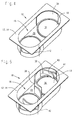
- Holder 10 has a storage compartment 12 with a top view rectangular edge 14 and an oval in plan view depression 16.
- the holder 10 has two compartment dividers 18, which in turn have turntables 36 which rotate on the Floor 28 of the storage compartment 12 are arranged.
- the turntables 36 are concentric with imaginary centers of the semicircular ends of the oval recess 16 of the Storage compartment 12 is arranged and about vertical axes of rotation through said Center points rotatable.
- the turntables 36 have a wall 38 which is approximately a quarter circle arc along a circumference of the turntable 36 extends.
- each wall 38 separates the compartment divider 18 a cup-shaped adjustment portion 30 for adjusting one in Figures 4 and 5 not shown beverage container from the rest of the storage compartment 12.
- the holder 10 of Figures 4 and 5 has for each of its two adjustment areas 30 a pivotable diameter compensation flap 40, which takes the form of a domed, having a strip-shaped finger.
- the diameter balancing flap 40 is in the range the semicircular side wall of the recess 16 at the ends of the recess 16th the storage compartment 12 is arranged.
- the diameter balancing flap 40 is one vertical, shown in Figure 5 with a dashed line pivot axis 42nd pivotable.
- the compensating flap has two up and downwardly projecting, not visible in the drawing bearing pin, which is rotatable are received in complementary bearing holes of the storage compartment 12.
- the diameter balancing flaps 40 depress one set beverage container against the wall 38 of the compartment divider 18 and hold This container with a smaller diameter tip over in the Adjustment openings 30.
- dividers 18 are turned to the non-use position, slide their Walls 38 along the inner sides of the disequilibrium valves 40 along and press the diameter balancing flaps 40 against the force of the spring elements outside in recesses 44, in the side wall of the recess 16 of the storage compartment 12th are attached.
- An interior of the recess 16 of the storage compartment 12 is characterized in the non-use position of the compartment divider 18 completely to insert Items available.
- inventive holder 10 is a modified Performance of the illustrated in Figures 4 and 5 and explained above holder 10th To avoid repetition, essentially only the Differences explained and it is otherwise with respect to the holder 10 of Figures 6 to 8 referenced to the comments on Figures 4 and 5.
- the holder 10 from FIGS. 6 to 8 has only one compartment divider 18.
- the compartment divider 18 has a turntable 36 which is below the bottom 28 of the storage compartment 12th is arranged.
- a wall 38 of the compartment divider 18 has approximately the shape of a Half cylinder on and extends over approximately 180 ° of a peripheral edge of the Turntable 36.
- the wall 38 is located in the illustrated in Figure 6 Non-use position on an outer side of the end of the recess 16 semi-cylindrical side wall of the recess 16 of the storage compartment 12.
- the compartment divider 18 of the holder 10 of Figures 6 to 8 is thus in its illustrated in Figure 6 Non-use position on an outer side of the storage compartment 12.
- the wall 38 of the compartment part 18 has a grip bead 46 at her End on that in the non-use position of the compartment divider 18 in the slot 46 in the side wall of the storage compartment 12 is located.
- holder 10 shown in Figures 4 and 5 also has in Figures 6 to 8 illustrated holder 10 a spring-loaded diameter balancing flap 40, when turning the compartment part 18 in the non-use position in a recess 44 is pivoted into the side wall of the storage compartment 12.
- This can be, as shown in Figure 8, a handle cup 52 so in Set the adjustment portion 30 of the holder 10 that a handle 54 of the handle cup 52nd the gap 50 passes through.
- the holder 10 according to the invention shown in FIGS. 9a-c and 10a-c has one Storage compartment 12 with a rectangular in plan view recess 16.
- a finger-shaped compartment divider 18 is arranged in which a finger-shaped compartment divider 18 is arranged.
- the compartment divider 18 is with a Pivot pin connection 58 pivotally mounted on the longitudinal side wall 56.
- the Trunnion 58 is located approximately in a longitudinal center of the Longitudinal side wall 56, it has a vertical pivot axis 60, which in Figures 10a-c is indicated by a dashed line.
- the compartment divider 18 In a non-use position shown in Figures 9a and 10a is the compartment divider 18 in the recess 57 of the longitudinal side wall 56, it closes flush with a Inside the longitudinal side wall 56 of the storage compartment 12 from.
- the compartment divider 18 can be by about 90 ° in a use position shown in Figures 9b and 10b in the Swivel storage compartment 12 into it.
- the compartment divider 18 divided the storage compartment 12 in an adjustment opening 30, in which in Figures 9b and 10b a Milk bottle 62 is set, and a remaining part of the storage compartment 12.
- One of Adjustment opening 30 facing side 64 of the compartment divider 18 is arcuate concave arched around the set milk bottle 32 or another set Beverage container to give reliable hold. It is basically possible to Divider 18 by more than 90 ° hineinverschwenkenbar into the storage compartment 12 to a larger opening 30 for larger beverage containers from the remaining part of the To be able to divide storage compartment 12.
- the compartment divider 18 is less than 90 ° from the Non-use position in another position of use in the storage compartment 12th hineinverschwenkt. In this position of use, the compartment divider 18 shares a smaller one Adjustment range 30 than in the position of use shown in FIGS. 9b and 10b Storage compartment 12 off.
- the holder 10 is characterized in beverage containers with different Diameter adaptable, in Figures 9c and 10c is, for example, a beverage can 32 in the Adjustment opening 30 of the holder 10 is set.
Abstract
Description
Die Erfindung betrifft einen Halter für einen Getränkebehälter wie bspw. eine Tasse, einen Becher oder eine Dose, mit den Merkmalen des Oberbegriffs des Anspruchs 1, der zum Einbau in einen Kraftwagen vorgesehen ist.The invention relates to a holder for a beverage container such as a cup, a cup or a can, with the features of the preamble of claim 1, which is intended for installation in a motor vehicle.
Derartige Halter sind an sich bekannt. Sie weisen eine Einstellöffnung auf, in die der Getränkebehälter einstellbar und in der der eingestellte Getränkebehälter kippsicher gehalten ist.Such holders are known per se. They have an insertion opening into which the Beverage container adjustable and in the set beverage container tip over is held.
Der Erfindung liegt die Aufgabe zugrunde, einen derartigen Halter platzsparend in einem Kraftwagen unterbringbar auszubilden.The invention has the object of providing such a holder to save space in a To train cars under housing.
Diese Aufgabe wird erfindungsgemäß durch die Merkmale des Anspruchs 1 gelöst. Der erfindungsgemäße Halter weist ein Ablagefach sowie einen Fachteiler auf, der mit einer Führung am Ablagefach zwischen einer Nichtgebrauchsstellung und einer Gebrauchsstellung hin- und zurückbewegbar geführt ist. In der Gebrauchsstellung unterteilt der Fachteiler das Ablagefach in einen Einstellbereich, in den ein Getränkebehälter einstellbar ist, und einen übrigen Bereich. In der Nichtgebrauchsstellung unterteilt der Fachteiler das Ablagefach nicht, so dass das gesamte Ablagefach zum Einlegen von Gegenständen zur Verfügung steht. In der Nichtgebrauchsstellung kann sich der Fachteiler bspw. versenkt in einem Boden des Ablagefachs, innen an einer Wand des Ablagefachs oder außerhalb des Ablagefachs befinden.This object is achieved by the features of claim 1. Of the Holder according to the invention has a storage compartment and a compartment divider, which with a Guide on the storage compartment between a non-use position and a Use position is guided back and forth movable. In the use position the compartment divider subdivides the storage compartment into an adjustment area into which a Beverage container is adjustable, and a remaining area. In the Not in use, the compartment divider does not divide the storage compartment, so that the entire storage compartment is available for loading objects. In the Not in use, the compartment divider can, for example, sunk in a floor of the Storage compartment, inside a wall of the storage compartment or outside of the storage compartment are located.
Die Erfindung hat den Vorteil, dass der Halter platzsparend in ein Ablagefach integriert ist, wobei bei Nichtgebrauch des Halters das gesamte Ablagefach und bei Gebrauch des Halters der nicht zum Einstellen des Getränkebehälters genutzte, übrige Bereich des Ablagefachs zum Einlegen von Gegenständen nutzbar ist. Der erfindungsgemäße Halter weist eine gute Bauraumnutzung auf. Weiterer Vorteil des erfindungsgemäßen Halters ist seine kostengünstige Herstellbarkeit aus wenigen Teilen. Prinzipiell ist es möglich, den Halter aus zwei Teilen, nämlich dem bspw. mulden- oder wannenförmigen Ablagefach und dem beweglich am Ablagefach geführten Fachteiler herzustellen.The invention has the advantage that the holder integrates space saving in a storage compartment is, when not in use of the holder, the entire storage compartment and when using the Holder of the not used for setting the beverage container, remaining area of the Tray for inserting objects is usable. The holder according to the invention has a good use of space. Another advantage of the holder according to the invention is its cost-effective manufacturability of few parts. In principle, it is possible the holder of two parts, namely the example trough or trough-shaped Storage compartment and the movably guided on the tray compartment divider produce.
Eine Weiterbildung der Erfindung sieht mehrere Gebrauchsstellungen vor, in die der Fachteiler bewegbar ist. In den verschiedenen Gebrauchsstellungen teilt der Fachteiler unterschiedlich große Einstellbereiche vom übrigen Ablagefach ab. Der Halter ist dadurch an unterschiedlich große Getränkebehälter anpassbar.A development of the invention provides several positions of use, in which the Divider is movable. In the different positions of use divides the compartment divider different adjustment ranges from the other storage compartment. The holder is thereby adaptable to different sized beverage containers.
Eine Ausgestaltung der Erfindung sieht eine Drehlagerung als Führung des Fachteilers vor. Der Fachteiler weist eine Wandung auf, die exzentrisch zur Drehachse des Fachteilers bspw. ein Umfangswandabschnitt sein kann. Durch Drehen des Fachteilers lässt sich dieser in die Gebrauchs- und die Nichtgebrauchsstellung bringen. In der Gebrauchsstellung befindet sich die zur Drehachse exzentrische Wandung des Fachteilers im Ablagefach und unterteilt dieses in den Einstellbereich und den übrigen Bereich. Diese Ausgestaltung der Erfindung lässt sich mit bspw. horizontaler oder vertikaler Drehachse ausbilden.An embodiment of the invention provides a pivot bearing as a guide of the compartment divider in front. The compartment divider has a wall which is eccentric to the axis of rotation of Partial divider, for example, may be a peripheral wall portion. By turning the compartment divider This can be brought into the use and non-use position. In the Use position is the eccentric to the axis of rotation of the Compartment divider in the storage compartment and divides this into the adjustment range and the rest Area. This embodiment of the invention can be with, for example, horizontal or train vertical axis of rotation.
Eine Weiterbildung der Erfindung sieht mehrere, bspw. zwei Fachteiler vor, um wahlweise einen oder mehrere Getränkebehälter in den Halter einstellen zu können. Diese Ausgestaltung der Erfindung bietet sich an, wenn das Ablagefach eine ausreichende Größe zum Einstellen mehrerer Getränkebehälter aufweist.A development of the invention provides several, for example. Two compartment divider to order optionally to be able to set one or more beverage containers in the holder. This embodiment of the invention is useful when the storage compartment a has sufficient size for setting a plurality of beverage containers.
Zum kippsicheren Halten von Getränkebehältern unterschiedlichen Durchmessers sieht eine Ausgestaltung der Erfindung eine Durchmesserausgleichsklappe vor, die vorzugsweise federbeaufschlagt ein Stück weit in den Einstellbereich des Halters hineinverschwenkt. Wird der Fachteiler in die Nichtgebrauchsstellung bewegt, bewegt er die Durchmesserausgleichsklappe aus dem Ablagefach hinaus oder zumindest an dessen Randbereich, damit die Durchmesserausgleichsklappe ein Fassungsvermögen des Ablagefachs nicht oder nur wenig verkleinert. Der Fachteiler bildet also einen Antrieb für die Durchmesserausgleichsklappe.For non-tilting holding drinks containers of different diameters looks an embodiment of the invention, a diameter compensating flap, the preferably spring loaded a little way into the adjustment of the holder hineinverschwenkt. If the compartment divider is moved into the non-use position, it moves the diameter balancing flap out of the storage compartment or at least its edge area, so that the diameter compensation flap a capacity of the storage compartment is not or only slightly reduced. The compartment divider thus forms one Drive for the diameter compensation flap.
Eine Ausgestaltung der Erfindung sieht eine Lücke zwischen dem Fachteiler und einer Wand des Ablagefachs vor, wenn sich der Fachteiler in der Gebrauchsstellung befindet. An embodiment of the invention provides a gap between the compartment divider and a Wall of the storage compartment before, when the compartment divider is in the use position.
Diese Aufgestaltung der Erfindung ermöglicht das Einstellen einer Henkeltasse in den Halter, wobei der Henkel der in den Halter eingestellten Tasse sich in der Lücke zwischen dem Fachteiler und der Wand des Ablagefachs befindet.This embodiment of the invention allows the setting of a handle cup in the Holder, wherein the handle of the cup set in the holder is in the gap located between the compartment divider and the wall of the storage compartment.
Die Erfindung wird nachfolgend anhand in der Zeichnung dargestellter Ausführungsbeispiele näher erläutert. Es zeigen:
- Figur 1
- eine erste Ausführungsform eines erfindungsgemäßen Halters in einer Nichtgebrauchsstellung in perspektivischer Darstellung;
- Figur 2
- den Halter aus Figur 1 mit einem eingestellten Getränkebehälter;
- Figuren 3a-c
- einen Längsschnitt des Halters aus Figur 1 in unterschiedlichen Stellungen;
- Figur 4
- eine zweite Ausführungsform eines erfindungsgemäßen Halters in einer Nichtgebrauchsstellung in perspektivischer Darstellung;
- Figur 5
- den Halter aus Figur 4 in einer Gebrauchsstellung;
- Figur 6
- eine dritte Ausführungsform eines erfindungsgemäßen Halters in einer Nichtgebrauchsstellung in perspektivischer Darstellung;
- Figur 7
- den Halter aus Figur 6 in einer Gebrauchsstellung;
- Figur 8
- den Halter aus Figur 7 mit einem eingestellten Getränkebehälter;
- Figur 9a-c
- eine vierte Ausführungsform eines erfindungsgemäßen Halters in unterschiedlichen Stellungen in Draufsicht; und
- Figuren 10a-c
- eine perspektivische Darstellung einer Ecke des Halters gemäß Figuren 9a-c.
- FIG. 1
- a first embodiment of a holder according to the invention in a non-use position in perspective view;
- FIG. 2
- the holder of Figure 1 with a set beverage container;
- FIGS. 3a-c
- a longitudinal section of the holder of Figure 1 in different positions;
- FIG. 4
- a second embodiment of a holder according to the invention in a non-use position in a perspective view;
- FIG. 5
- the holder of Figure 4 in a position of use;
- FIG. 6
- a third embodiment of a holder according to the invention in a non-use position in perspective view;
- FIG. 7
- the holder of Figure 6 in a position of use;
- FIG. 8
- the holder of Figure 7 with a set beverage container;
- Figure 9a-c
- a fourth embodiment of a holder according to the invention in different positions in plan view; and
- Figures 10a-c
- a perspective view of a corner of the holder according to Figures 9a-c.
Die Zeichnungen sind als vereinfachte und schematisierte Darstellungen zu verstehen. The drawings are to be understood as simplified and schematic representations.
Der in Figur 1 dargestellte, erfindungsgemäße Halter 10 zum Halten eines
Getränkbehälters wie bspw. einer Tasse, eines Bechers oder einer Dose ist zum Einbau
in einen nicht dargestellten Kraftwagen vorgesehen. Der Halter 10 weist ein muldenoder
wannenförmiges Ablagefach 12 mit einem in Draufsicht eckigen Rand 14 und einer
in Draufsicht ovalen Vertiefung 16 auf. Der Rand 14 dient zum Einbau des Halters 10 in
bspw. eine Mittelkonsole eines nicht dargestellten Kraftwagens.The illustrated in Figure 1,
Ungefähr in einer Längsmitte der Vertiefung 16 ist ein Fachteiler 18 quer angeordnet.
Der Fachteiler 18 weist an seinen beiden Enden kreisförmige Stirnscheiben 20 auf, die
mit einem Steg 22 einstückig verbunden sind. Der Steg 22 befindet sich an einer
Umfangsstelle der Stirnscheiben 20, er bildet eine Wandung des Fachteilers 18. Die
Stirnscheiben 20 sind in Seitenwänden der Vertiefung 16 des Ablagefachs 12 versenkt
angeordnet. Die Stirnscheiben 20 weisen in ihren Mitten nach außen abstehende
Lagerzapfen 24 auf, die drehbar in Lagerlöchern in den Seitenwänden der Vertiefung 16
einliegen. Die Lagerzapfen 24 bilden mit den Lagerlöchern eine Drehlagerung des
Fachteilers 18. Eine Drehachse 26 ist in Figur 1 mit einer Strichpunktlinie dargestellt, sie
verläuft quer und horizontal ungefähr in halber Höhe durch die Vertiefung 16 des
Ablagefachs 12. Der Steg 22 ist parallel und exzentrisch zur Drehachse 26 angeordnet.Approximately in a longitudinal center of the
In einer in Figur 1 dargestellten Nichtgebrauchsstellung des Fachteilers 18 liegt der Steg
22 versenkt in einer Vertiefung 23 in einem Boden 28 des Ablagefachs 12 ein. Die
Nichtgebrauchsstellung des Fachteilers 18 ist auch in Figur 3a dargestellt. Durch Drehen
des Fachteilers 18 um die Drehachse 26 lässt sich der Steg 22 und damit der Fachteiler
18 selbst in verschiedene Gebrauchsstellungen bewegen, wie sie in Figuren 2, 3b und
3c dargestellt sind. In Figuren 2 und 3b ist der Steg 22 in seine höchste Stellung bewegt,
er unterteilt das Ablagefach 12 in einen Einstellbereich 30 zum Einstellen bspw. einer
Getränkedose 32, wie in Figuren 2 und 3b dargestellt, und einen übrigen Bereich 34, der
zum Einlegen von Gegenständen nutzbar ist. In Figur 3c ist der Fachteiler durch
Drehung um 90° gegenüber der Nichtgebrauchsstellung in eine andere
Gebrauchsstellung gedreht, in der der Steg 22 einen kleineren Einstellbereich 30 zum
Einstellen eines im Durchmesser kleineren Getränkbehälters, und einen übrigen,
größeren Bereich unterteilt. Durch die verschiedenen Gebrauchsstellungen des
Fachteilers 18 lässt sich die Größe des Einstellbereichs 30 an Getränkebehälter 32
verschieden großen Durchmessers anpassen. In a non-use position of the
Zur Arretierung des Fachteilers 18 in der jeweiligen Stellung ist ein in der Zeichnung
nicht sichtbarer Rastmechanismus vorgesehen, der mit einer Lösetaste 35 entriegelbar
ist. Derartige Rastmechanismen sind dem Fachmann bekannt und sollen, da sie nicht
den eigentlichen Gegenstand der Erfindung bilden, an dieser Stelle nicht näher erläutert
werden.To lock the
Zur Erläuterung der weiteren Figuren werden nachfolgend für übereinstimmende
Bauteile gleiche Bezugszahlen wie in Figuren 1-3 verwendet. Der in Figur 4 dargestellte,
erfindungsgemäße Halter 10 weist ein Ablagefach 12 mit einem in Draufsicht
rechteckigen Rand 14 und einer in Draufsicht ovalen Vertiefung 16 auf. Der Halter 10
weist zwei Fachteiler 18 auf, die ihrerseits Drehteller 36 aufweisen, die drehbar auf dem
Boden 28 des Ablagefachs 12 angeordnet sind. Die Drehteller 36 sind konzentrisch zu
gedachten Mittelpunkten der halbkreisförmigen Enden der ovalen Vertiefung 16 des
Ablagefachs 12 angeordnet und um vertikale Drehachsen durch die genannten
Mittelpunkte drehbar. Die Drehteller 36 weisen eine Wandung 38 auf, die sich um etwa
einen Viertelkreisbogen entlang eines Umfangs der Drehteller 36 erstreckt. Durch
Drehen der Drehteller 36 bzw. der Fachteiler 18 sind die Wandungen 38 aus der in Figur
4 dargestellten Nichtgebrauchsstellung in die in Figur 5 dargestellte Gebrauchsstellung
bewegbar. In der Nichtgebrauchsstellung liegen die Wandungen 38 innen an einer am
Ende der Vertiefung 16 halbzylinderförmigen Seitenwand der Vertiefung 16 des
Ablagefachs 12 an. In der Gebrauchsstellung trennt jede Wandung 38 der Fachteiler 18
einen topfförmigen Einstellbereich 30 zum Einstellen eines in Figuren 4 und 5 nicht
dargestellten Getränkebehälters vom übrigen Ablagefach 12 ab.To explain the other figures are below for matching
Components same reference numerals as used in Figures 1-3. The illustrated in Figure 4,
Der Halter 10 aus Figuren 4 und 5 weist für jeden seiner beiden Einstellbereiche 30 eine
schwenkbare Durchmesserausgleichsklappe 40 auf, die die Form eines gewölbten,
leistenförmigen Fingers aufweist. Die Durchmesserausgleichsklappe 40 ist im Bereich
der halbkreisförmigen Seitenwand der Vertiefung 16 an den Enden der Vertiefung 16
des Ablagefachs 12 angeordnet. Die Durchmesserausgleichsklappe 40 ist um eine
vertikale, in Figur 5 mit einer Strichpunktlinie dargestellte Schwenkachse 42
schwenkbar. Zur Schwenklagerung weist die Ausgleichsklappe zwei nach oben und
nach unten abstehende, in der Zeichnung nicht sichtbare Lagerzapfen auf, die drehbar
in komplementären Lagerlöcher des Ablagefachs 12 aufgenommen sind. Ein in der
Zeichnung ebenfalls nicht sichtbares Federelement, das als Schenkelfeder ausgebildet
ist, schwenkt die Durchmesserausgleichsklappen 40 in die Einstellbereiche 30 hinein,
wie in Figur 5 dargestellt. Die Durchmesserausgleichsklappen 40 drücken einen
eingestellten Getränkebehälter gegen die Wandung 38 der Fachteiler 18 und halten
dadurch Getränkebehälter mit kleinerem Durchmesser kippsicher in den
Einstellöffnungen 30.The
Werden die Fachteiler 18 in die Nichtgebrauchsstellung gedreht, gleiten ihre
Wandungen 38 an Innenseiten der Durchmesserausgleichsklappen 40 entlang und
drücken die Durchmesserausgleichsklappen 40 gegen die Kraft der Federelemente nach
außen in Aussparungen 44, die in der Seitenwand der Vertiefung 16 des Ablagefachs 12
angebracht sind. Ein Innenraum der Vertiefung 16 des Ablagefachs 12 steht dadurch in
der Nichtgebrauchsstellung der Fachteiler 18 vollständig zum Einlegen von
Gegenständen zur Verfügung.If the
Der in Figuren 6 bis 8 dargestellte, erfindungsgemäße Halter 10 ist eine abgewandelte
Aufführung des in Figuren 4 und 5 dargestellten und vorstehend erläuterten Halters 10.
Zur Vermeidung von Widerholungen werden nachfolgend im wesentlichen nur die
Unterschiede erläutert und es wird im übrigen hinsichtlich des Halters 10 aus Figuren 6
bis 8 auf die Ausführungen zu Figuren 4 und 5 verwiesen.The illustrated in Figures 6 to 8,
Der Halter 10 aus Figuren 6 bis 8 weist nur einen Fachteiler 18 auf. Der Fachteiler 18
weist einen Drehteller 36 auf, der unterhalb des Bodens 28 des Ablagefachs 12
angeordnet ist. Eine Wandung 38 des Fachteilers 18 weist ungefähr die Form eines
Halbzylinders auf und erstreckt sich über ungefähr 180° eines Umfangrandes des
Drehtellers 36. Die Wandung 38 befindet sich in der in Figur 6 dargestellten
Nichtgebrauchsstellung auf einer Außenseite der am Ende der Vertiefung 16
halbzylinderförmigen Seitenwand der Vertiefung 16 des Ablagefachs 12. Der Fachteiler
18 des Halters 10 aus Figuren 6 bis 8 befindet sich also in seiner in Figur 6 dargestellten
Nichtgebrauchsstellung an einer Außenseite des Ablagefachs 12. Durch Drehen des
Fachteilers 18 in die in Figuren 7 und 8 dargestellte Gebrauchsstellung gelangt die
Wandung 38 des Fachteilers 18 in das Ablagefach 12 hinein und teilt eine in etwa
zylinderförmige Einstellöffnung 30 vom übrigen Teil des Ablagefachs 12 ab. Die
Seitenwand der Vertiefung 16 des Ablagefachs 12 ist mit einem Schlitz 46 versehen,
durch den die Wandung 38 beim Drehen des Fachteilers 18 aus der
Nichtgebrauchsstellung in die Gebrauchsstellung in die Vertiefung 16 eintritt. Zwischen
der Wandung 38 und dem Drehteller 36 besteht ein Schlitz für den Boden 28 des
Ablagefachs 12, da sich die Wandung 38 oberhalb und er Drehteller 36 unterhalb des
Bodens 28 befindet. Um den Fachteiler 18 in der Nichtgebrauchsstellung greifen und
drehen zu können, weist die Wandung 38 des Fachteiles 18 einen Griffwulst 46 an ihrem
Ende auf, dass sich in der Nichtgebrauchsstellung des Fachteilers 18 im Schlitz 46 in
der Seitenwand des Ablagefachs 12 befindet.The
Ebenso wie der in Figuren 4 und 5 dargestellte Halter 10 weist auch der in Figuren 6 bis
8 dargestellte Halter 10 eine federbeaufschlagte Durchmesserausgleichsklappe 40 auf,
die beim Drehen des Fachteiles 18 in die Nichtgebrauchsstellung in eine Ausnehmung
44 in der Seitenwand des Ablagefachs 12 hineinverschwenkt wird.As well as the
Wie in Figuren 7 und 8 zu sehen, besteht in der Gebrauchsstellung des Fachteilers 18
eine Lücke 50 zwischen der Wandung 38 des Fachteilers 18 und der Seitenwand des
Ablagefachs 12. Dadurch lässt sich, wie in Figur 8 dargestellt, eine Henkeltasse 52 so in
den Einstellbereich 30 des Halters 10 einstellen, dass ein Henkel 54 der Henkeltasse 52
die Lücke 50 durchgreift.As can be seen in FIGS. 7 and 8, in the position of use of the compartment divider 18
a
Der in Figuren 9a-c und 10a-c dargestellte, erfindungsgemäße Halter 10 weist ein
Ablagefach 12 mit einer in Draufsicht rechteckigen Vertiefung 16 auf. In einer
Längsseitenwand 56 des Ablagefachs 12 ist eine Ausnehmung angebracht, in der ein
fingerförmiger Fachteiler 18 angeordnet ist. Der Fachteiler 18 ist mit einer
Schwenkzapfenverbindung 58 schwenkbar an der Längsseitenwand 56 gelagert. Die
Schwenkzapfenlagerung 58 befindet sich ungefähr in einer Längsmitte der
Längsseitenwand 56, sie weist eine vertikale Schwenkachse 60 auf, die in Figuren 10a-c
mit einer Strichpunktlinie angedeutet ist.The
In einer in Figuren 9a und 10a dargestellten Nichtgebrauchsstellung liegt der Fachteiler
18 in der Ausnehmung 57 der Längsseitenwand 56 ein, er schließt bündig mit einer
Innenseite der Längsseitenwand 56 des Ablagefachs 12 ab. Der Fachteiler 18 lässt sich
um ca. 90° in eine in Figuren 9b und 10b dargestellte Gebrauchsstellung in das
Ablagefach 12 hineinverschwenken. In der Gebrauchstellung unterteilt der Fachteiler 18
das Ablagefach 12 in eine Einstellöffnung 30, in die in Figuren 9b und 10b eine
Milchflasche 62 eingestellt ist, und einen übrigen Teil des Ablagefachs 12. Eine der
Einstellöffnung 30 zugewandte Seite 64 des Fachteilers 18 ist bogenförmig konkav
gewölbt um der eingestellten Milchflasche 32 oder einem sonstigen eingestellten
Getränkebehälter zuverlässigen Halt zu geben. Es ist grundsätzlich möglich, den
Fachteiler 18 um mehr als 90° in das Ablagefach 12 hineinverschwenkenbar vorzusehen
um eine größere Einstellöffnung 30 für größere Getränkebehälter vom übrigen Teil des
Ablagefachs 12 abteilen zu können.In a non-use position shown in Figures 9a and 10a is the
In Figuren 9c und 10c ist der Fachteiler 18 um weniger als 90° aus der
Nichtgebrauchsstellung in eine andere Gebrauchsstellung in das Ablagefach 12
hineinverschwenkt. In dieser Gebrauchsstellung teilt der Fachteiler 18 einen kleineren
Einstellbereich 30 als in der in Figuren 9b und 10 b dargestellten Gebrauchsstellung vom
Ablagefach 12 ab. Der Halter 10 ist dadurch an Getränkebehälter mit verschiedenem
Durchmesser anpassbar, in Figuren 9c und 10c ist bspw. eine Getränkedose 32 in die
Einstellöffnung 30 des Halters 10 eingestellt.In Figures 9c and 10c, the
Claims (9)
Applications Claiming Priority (2)
| Application Number | Priority Date | Filing Date | Title |
|---|---|---|---|
| DE10134027 | 2001-07-12 | ||
| DE2001134027 DE10134027A1 (en) | 2001-07-12 | 2001-07-12 | Holder for a beverage container |
Publications (3)
| Publication Number | Publication Date |
|---|---|
| EP1277613A2 true EP1277613A2 (en) | 2003-01-22 |
| EP1277613A3 EP1277613A3 (en) | 2003-05-02 |
| EP1277613B1 EP1277613B1 (en) | 2006-12-20 |
Family
ID=7691624
Family Applications (1)
| Application Number | Title | Priority Date | Filing Date |
|---|---|---|---|
| EP20020012217 Expired - Lifetime EP1277613B1 (en) | 2001-07-12 | 2002-06-04 | Holder for beverage containers |
Country Status (2)
| Country | Link |
|---|---|
| EP (1) | EP1277613B1 (en) |
| DE (2) | DE10134027A1 (en) |
Cited By (9)
| Publication number | Priority date | Publication date | Assignee | Title |
|---|---|---|---|---|
| DE102007006575A1 (en) | 2007-02-09 | 2008-08-21 | Lisa Dräxlmaier GmbH | Support for steady holding of articles at different heights and different surface dimensions in vehicles, has base surface with pronounced linear extensions and side walls are arranged perpendicular to base surface |
| DE102007061203A1 (en) * | 2007-12-19 | 2009-06-25 | GM Global Technology Operations, Inc., Detroit | Cup holder for cars has hinged lid sections and swiveling clips which hold cups, bottles, etc. upright |
| DE102008029259A1 (en) * | 2007-12-19 | 2009-12-24 | GM Global Technology Operations, Inc., Detroit | Receiving element, in particular for motor vehicles, for receiving a container |
| WO2010136130A1 (en) * | 2009-05-29 | 2010-12-02 | Volkswagen Aktiengesellschaft | Retaining device, particularly for drink containers |
| US8011710B2 (en) | 2008-06-19 | 2011-09-06 | GM Global Technology Operations LLC | Fixture element, in particular for motor vehicles, for holding a receptacle |
| CN102452346A (en) * | 2010-10-28 | 2012-05-16 | 比亚迪股份有限公司 | Vehicular cup holder |
| DE102011100833A1 (en) * | 2011-05-07 | 2012-11-08 | Volkswagen Aktiengesellschaft | Holder for holding pot-shaped beverage container e.g. cup, in front seat of car, has insert part inserted into receiving space, where receiving space is provided for insertion of container, and compensating elements covered with insert part |
| DE102015208828A1 (en) * | 2015-05-12 | 2016-11-17 | Bayerische Motoren Werke Aktiengesellschaft | motor vehicle |
| CN111086432A (en) * | 2018-10-24 | 2020-05-01 | 奥迪股份公司 | Holding device for beverage containers |
Families Citing this family (21)
| Publication number | Priority date | Publication date | Assignee | Title |
|---|---|---|---|---|
| DE10329959B4 (en) * | 2003-07-03 | 2015-08-06 | Fischer Automotive Systems Gmbh & Co. Kg | Holder for a beverage container |
| DE102004011306A1 (en) * | 2004-03-09 | 2005-09-29 | Fischer Automotive Systems Gmbh | Oddments tray for use in motor vehicle for inserting e.g. mobile phone, has slider movable into two positions and manufactured as separate part, where tray is individual component of dashboard, center console or other parts of motor vehicle |
| DE202007018119U1 (en) | 2007-09-21 | 2008-03-13 | Dr. Schneider Kunststoffwerke Gmbh | Device for holding beverage containers |
| DE102007061898A1 (en) * | 2007-12-20 | 2009-06-25 | Fischer Automotive Systems Gmbh & Co. Kg | shelf |
| DE102008004267A1 (en) * | 2008-01-14 | 2009-07-16 | Bayerische Motoren Werke Aktiengesellschaft | Fixing part for use as e.g. cup holder, in motor vehicle, has mounting plate component pushing object against side wall of storage case and having side wall forming wall of housing with another side wall of case in retracted position |
| DE102008047479A1 (en) * | 2008-09-17 | 2010-04-15 | Bayerische Motoren Werke Aktiengesellschaft | Interior equipment part for use in motor vehicle, has compartment limited by side walls and base, and cup holder arranged opposite to edge area of side walls, where holder has mounting plate that is arranged at base in rotatable manner |
| DE102008060963A1 (en) * | 2008-12-06 | 2010-06-10 | Bayerische Motoren Werke Aktiengesellschaft | Vehicle, particularly passenger vehicle, has holding system for containers, where holding system is arranged at inner space of component, and has holder that is adjusted in locked non-operating position in recess |
| DE102008060964A1 (en) * | 2008-12-06 | 2010-06-10 | Bayerische Motoren Werke Aktiengesellschaft | Vehicle i.e. passenger car, has retainers accommodated in recess formed at wall of receptacles in locked position, where space formed between receptacles is differently usable by modular inserts |
| DE102009000972A1 (en) | 2009-02-18 | 2010-08-19 | Ford Global Technologies, LLC, Dearborn | Storage shelf for storing beverage container in motor vehicle, has rotary bearings with axis of rotation arranged in horizontal direction, and shelf dividers with walls that are L-shaped in cross-sections, where walls are movable in shelf |
| DE102009030576B4 (en) | 2009-06-26 | 2019-07-18 | GM Global Technology Operations LLC (n. d. Ges. d. Staates Delaware) | Device for the lateral positioning of an object in a container |
| DE102009030577A1 (en) | 2009-06-26 | 2011-01-05 | GM Global Technology Operations, Inc., Detroit | Console of a motor vehicle with a container for receiving an object |
| DE102009049363A1 (en) * | 2009-10-14 | 2011-04-21 | GM Global Technology Operations, Inc., Detroit | Storage device i.e. center console, for storing e.g. cups, in passenger car, has side wall and bottom part laterally and downwardly defining space, where movable sections are movable for partitioning space between fixed and movable sections |
| DE102011085384A1 (en) * | 2011-10-28 | 2013-05-02 | Bayerische Motoren Werke Aktiengesellschaft | Storage compartment of motor car, has container that is inserted into receiving space, and holding element that is provided to secure and release container in receiving space |
| DE102013105469B4 (en) | 2013-05-28 | 2017-07-20 | Dr. Schneider Kunststoffwerke Gmbh | Device preferably for holding beverage containers in a motor vehicle |
| DE102013114025B4 (en) | 2013-12-13 | 2017-07-20 | Dr. Schneider Kunststoffwerke Gmbh | Device in a motor vehicle |
| DE102014220595B4 (en) * | 2014-10-10 | 2019-09-12 | Bos Gmbh & Co. Kg | Receiving device for at least one food or beverage container in a motor vehicle |
| DE102015002669B4 (en) | 2015-03-02 | 2021-09-30 | Audi Ag | Storage device for arrangement in a motor vehicle |
| DE102015217215B4 (en) * | 2015-09-09 | 2023-03-09 | Volkswagen Aktiengesellschaft | Beverage Container Holder |
| DE102016101689A1 (en) | 2016-02-01 | 2017-08-03 | Fischer Automotive Systems Gmbh & Co. Kg | Storage compartment with a holder for a beverage container |
| DE102017111699A1 (en) * | 2017-05-30 | 2018-12-06 | Fischer Automotive Systems Gmbh & Co. Kg | Storage compartment with a holder for a beverage container |
| DE102021110665B4 (en) | 2021-04-27 | 2023-02-02 | Audi Aktiengesellschaft | Storage compartment with an insertion opening, via which a beverage container can be placed in a storage space of the storage compartment, console for a vehicle, vehicle |
Family Cites Families (6)
| Publication number | Priority date | Publication date | Assignee | Title |
|---|---|---|---|---|
| US5170980A (en) * | 1991-04-26 | 1992-12-15 | Prince Corporation | Container holder |
| DE4200823A1 (en) * | 1992-01-15 | 1993-07-22 | Bayerische Motoren Werke Ag | Drink container holder with retaining aperture - has several holding elements swivelable into open and closed position |
| JPH09104278A (en) * | 1995-10-09 | 1997-04-22 | Aichi Mach Ind Co Ltd | Cup supporter |
| US5752686A (en) * | 1995-11-29 | 1998-05-19 | Deere & Company | Beverage container holder with pivoting collar |
| JP3665173B2 (en) * | 1997-02-26 | 2005-06-29 | マツダ株式会社 | Container holding device |
| US5921519A (en) * | 1997-10-02 | 1999-07-13 | Prince Corporation | Pivotal arm container holder |
-
2001
- 2001-07-12 DE DE2001134027 patent/DE10134027A1/en not_active Withdrawn
-
2002
- 2002-06-04 EP EP20020012217 patent/EP1277613B1/en not_active Expired - Lifetime
- 2002-06-04 DE DE50208987T patent/DE50208987D1/en not_active Expired - Lifetime
Non-Patent Citations (1)
| Title |
|---|
| None |
Cited By (14)
| Publication number | Priority date | Publication date | Assignee | Title |
|---|---|---|---|---|
| DE102007006575B4 (en) * | 2007-02-09 | 2009-10-29 | Lisa Dräxlmaier GmbH | Cupholder with spring-loaded flap |
| DE102007006575A1 (en) | 2007-02-09 | 2008-08-21 | Lisa Dräxlmaier GmbH | Support for steady holding of articles at different heights and different surface dimensions in vehicles, has base surface with pronounced linear extensions and side walls are arranged perpendicular to base surface |
| US8419101B2 (en) | 2007-12-19 | 2013-04-16 | GM Global Technology Operations LLC | Receiving element, in particular for accommodating a container |
| DE102007061203A1 (en) * | 2007-12-19 | 2009-06-25 | GM Global Technology Operations, Inc., Detroit | Cup holder for cars has hinged lid sections and swiveling clips which hold cups, bottles, etc. upright |
| DE102008029259A1 (en) * | 2007-12-19 | 2009-12-24 | GM Global Technology Operations, Inc., Detroit | Receiving element, in particular for motor vehicles, for receiving a container |
| DE102008029259B4 (en) * | 2007-12-19 | 2019-10-10 | GM Global Technology Operations LLC (n. d. Ges. d. Staates Delaware) | Receiving element, in particular for motor vehicles, for receiving a container |
| US8011710B2 (en) | 2008-06-19 | 2011-09-06 | GM Global Technology Operations LLC | Fixture element, in particular for motor vehicles, for holding a receptacle |
| WO2010136130A1 (en) * | 2009-05-29 | 2010-12-02 | Volkswagen Aktiengesellschaft | Retaining device, particularly for drink containers |
| CN102452346A (en) * | 2010-10-28 | 2012-05-16 | 比亚迪股份有限公司 | Vehicular cup holder |
| CN102452346B (en) * | 2010-10-28 | 2014-07-30 | 比亚迪股份有限公司 | Vehicular cup holder |
| DE102011100833A1 (en) * | 2011-05-07 | 2012-11-08 | Volkswagen Aktiengesellschaft | Holder for holding pot-shaped beverage container e.g. cup, in front seat of car, has insert part inserted into receiving space, where receiving space is provided for insertion of container, and compensating elements covered with insert part |
| DE102015208828A1 (en) * | 2015-05-12 | 2016-11-17 | Bayerische Motoren Werke Aktiengesellschaft | motor vehicle |
| CN111086432A (en) * | 2018-10-24 | 2020-05-01 | 奥迪股份公司 | Holding device for beverage containers |
| CN111086432B (en) * | 2018-10-24 | 2022-04-29 | 奥迪股份公司 | Holding device for beverage containers |
Also Published As
| Publication number | Publication date |
|---|---|
| DE50208987D1 (en) | 2007-02-01 |
| EP1277613B1 (en) | 2006-12-20 |
| EP1277613A3 (en) | 2003-05-02 |
| DE10134027A1 (en) | 2003-01-23 |
Similar Documents
| Publication | Publication Date | Title |
|---|---|---|
| EP1277613A2 (en) | Holder for beverage containers | |
| EP0667258A1 (en) | Device for holding drink containers | |
| EP1255662B1 (en) | Holder for a drinks container | |
| EP2072329B1 (en) | Storage compartment | |
| EP0756965B1 (en) | Support for two beverage containers | |
| EP0764558B1 (en) | Mounting structure especially for vehicles | |
| DE102015226812A1 (en) | Folding table structure for vehicles | |
| DE202014100120U1 (en) | Multiple container holder assembly | |
| DE102006034788A1 (en) | Motor vehicle storage device | |
| EP2039566B1 (en) | Device for holding drinks containers | |
| EP1312501A2 (en) | Arrangement of container and cupholder for means of locomotion | |
| DE4423097A1 (en) | Holder for liquid receptacles | |
| DE102008024695A1 (en) | Holding device for storage goods | |
| DE102007042126A1 (en) | Rotatable storage compartment for storing objects in a vehicle | |
| EP2014508A2 (en) | Storage compartment and holder for a drinks container | |
| DE102016101689A1 (en) | Storage compartment with a holder for a beverage container | |
| EP4110136B1 (en) | Device for the translatory and rotary movement of an item relative to a carrier panel | |
| DE3534098C2 (en) | ||
| DE102020100358B4 (en) | Folding device for a multifunctional piece of furniture | |
| DE102012010337A1 (en) | Body part and container arrangement for retaining spare wheel in spare wheel trough of passenger car, has container rotatable in lifted position, where projection and embossment attach container relative to body part in rotation direction | |
| DE19615743C1 (en) | Arm rest with hollow, upwardly open basic body | |
| DE102021134568A1 (en) | CUP HOLDING DEVICE OF THE CONCEALED TYPE, VEHICLE ARMREST HAVING THE HOLDING DEVICE, AND MEANS OF TRANSPORTATION HAVING THE SAME | |
| DE202004019209U1 (en) | Drinks holding device for cans, bottles and similar containers in a motor vehicle has a subassembly for supporting a container to be held in a vertical direction | |
| DE19942638A1 (en) | Holder for drinks containers in motor vehicles is located within hollow space and remains in that space when moved into use position | |
| EP0900697A2 (en) | Support bracket and housings for luxury requisites in the interior of a vehicle |
Legal Events
| Date | Code | Title | Description |
|---|---|---|---|
| PUAI | Public reference made under article 153(3) epc to a published international application that has entered the european phase |
Free format text: ORIGINAL CODE: 0009012 |
|
| AK | Designated contracting states |
Kind code of ref document: A2 Designated state(s): AT BE CH CY DE DK ES FI FR GB GR IE IT LI LU MC NL PT SE TR |
|
| AX | Request for extension of the european patent |
Free format text: AL;LT;LV;MK;RO;SI |
|
| PUAL | Search report despatched |
Free format text: ORIGINAL CODE: 0009013 |
|
| AK | Designated contracting states |
Designated state(s): AT BE CH CY DE DK ES FI FR GB GR IE IT LI LU MC NL PT SE TR |
|
| AX | Request for extension of the european patent |
Extension state: AL LT LV MK RO SI |
|
| 17P | Request for examination filed |
Effective date: 20030829 |
|
| AKX | Designation fees paid |
Designated state(s): DE ES FR GB IT SE |
|
| GRAP | Despatch of communication of intention to grant a patent |
Free format text: ORIGINAL CODE: EPIDOSNIGR1 |
|
| GRAS | Grant fee paid |
Free format text: ORIGINAL CODE: EPIDOSNIGR3 |
|
| GRAA | (expected) grant |
Free format text: ORIGINAL CODE: 0009210 |
|
| AK | Designated contracting states |
Kind code of ref document: B1 Designated state(s): DE ES FR GB IT SE |
|
| PG25 | Lapsed in a contracting state [announced via postgrant information from national office to epo] |
Ref country code: IT Free format text: LAPSE BECAUSE OF FAILURE TO SUBMIT A TRANSLATION OF THE DESCRIPTION OR TO PAY THE FEE WITHIN THE PRESCRIBED TIME-LIMIT;WARNING: LAPSES OF ITALIAN PATENTS WITH EFFECTIVE DATE BEFORE 2007 MAY HAVE OCCURRED AT ANY TIME BEFORE 2007. THE CORRECT EFFECTIVE DATE MAY BE DIFFERENT FROM THE ONE RECORDED. Effective date: 20061220 |
|
| REG | Reference to a national code |
Ref country code: GB Ref legal event code: FG4D Free format text: NOT ENGLISH |
|
| REF | Corresponds to: |
Ref document number: 50208987 Country of ref document: DE Date of ref document: 20070201 Kind code of ref document: P |
|
| PG25 | Lapsed in a contracting state [announced via postgrant information from national office to epo] |
Ref country code: SE Free format text: LAPSE BECAUSE OF FAILURE TO SUBMIT A TRANSLATION OF THE DESCRIPTION OR TO PAY THE FEE WITHIN THE PRESCRIBED TIME-LIMIT Effective date: 20070320 |
|
| PG25 | Lapsed in a contracting state [announced via postgrant information from national office to epo] |
Ref country code: ES Free format text: LAPSE BECAUSE OF FAILURE TO SUBMIT A TRANSLATION OF THE DESCRIPTION OR TO PAY THE FEE WITHIN THE PRESCRIBED TIME-LIMIT Effective date: 20070331 |
|
| GBT | Gb: translation of ep patent filed (gb section 77(6)(a)/1977) |
Effective date: 20070320 |
|
| ET | Fr: translation filed | ||
| PLBE | No opposition filed within time limit |
Free format text: ORIGINAL CODE: 0009261 |
|
| STAA | Information on the status of an ep patent application or granted ep patent |
Free format text: STATUS: NO OPPOSITION FILED WITHIN TIME LIMIT |
|
| 26N | No opposition filed |
Effective date: 20070921 |
|
| REG | Reference to a national code |
Ref country code: FR Ref legal event code: CJ Effective date: 20150112 Ref country code: FR Ref legal event code: CD Owner name: FISCHER AUTOMOTIVE SYSTEMS GMBH & CO. KG Effective date: 20150112 |
|
| REG | Reference to a national code |
Ref country code: FR Ref legal event code: TP Owner name: VOLKSWAGEN AG, DE Effective date: 20150505 |
|
| REG | Reference to a national code |
Ref country code: GB Ref legal event code: 732E Free format text: REGISTERED BETWEEN 20150528 AND 20150603 |
|
| REG | Reference to a national code |
Ref country code: FR Ref legal event code: PLFP Year of fee payment: 15 |
|
| REG | Reference to a national code |
Ref country code: FR Ref legal event code: PLFP Year of fee payment: 16 |
|
| PGFP | Annual fee paid to national office [announced via postgrant information from national office to epo] |
Ref country code: GB Payment date: 20170630 Year of fee payment: 16 |
|
| REG | Reference to a national code |
Ref country code: FR Ref legal event code: PLFP Year of fee payment: 17 |
|
| GBPC | Gb: european patent ceased through non-payment of renewal fee |
Effective date: 20180604 |
|
| PG25 | Lapsed in a contracting state [announced via postgrant information from national office to epo] |
Ref country code: GB Free format text: LAPSE BECAUSE OF NON-PAYMENT OF DUE FEES Effective date: 20180604 |
|
| PGFP | Annual fee paid to national office [announced via postgrant information from national office to epo] |
Ref country code: FR Payment date: 20190625 Year of fee payment: 18 |
|
| PG25 | Lapsed in a contracting state [announced via postgrant information from national office to epo] |
Ref country code: FR Free format text: LAPSE BECAUSE OF NON-PAYMENT OF DUE FEES Effective date: 20200630 |
|
| PGFP | Annual fee paid to national office [announced via postgrant information from national office to epo] |
Ref country code: DE Payment date: 20210519 Year of fee payment: 20 |
|
| REG | Reference to a national code |
Ref country code: DE Ref legal event code: R071 Ref document number: 50208987 Country of ref document: DE |