EP1277585A1 - An apparatus for transporting fluid ink, a flexible hose suitable for such apparatus, and the use of such a hose - Google Patents
An apparatus for transporting fluid ink, a flexible hose suitable for such apparatus, and the use of such a hose Download PDFInfo
- Publication number
- EP1277585A1 EP1277585A1 EP02077778A EP02077778A EP1277585A1 EP 1277585 A1 EP1277585 A1 EP 1277585A1 EP 02077778 A EP02077778 A EP 02077778A EP 02077778 A EP02077778 A EP 02077778A EP 1277585 A1 EP1277585 A1 EP 1277585A1
- Authority
- EP
- European Patent Office
- Prior art keywords
- ink
- hose
- acrylate
- alkyl
- hoses
- Prior art date
- Legal status (The legal status is an assumption and is not a legal conclusion. Google has not performed a legal analysis and makes no representation as to the accuracy of the status listed.)
- Granted
Links
- 239000012530 fluid Substances 0.000 title claims abstract description 10
- 239000000463 material Substances 0.000 claims abstract description 92
- XLYOFNOQVPJJNP-UHFFFAOYSA-N water Substances O XLYOFNOQVPJJNP-UHFFFAOYSA-N 0.000 claims abstract description 26
- OKTJSMMVPCPJKN-UHFFFAOYSA-N Carbon Chemical compound [C] OKTJSMMVPCPJKN-UHFFFAOYSA-N 0.000 claims abstract description 16
- 229910052799 carbon Inorganic materials 0.000 claims abstract description 16
- 125000002947 alkylene group Chemical group 0.000 claims description 13
- 125000005250 alkyl acrylate group Chemical group 0.000 claims description 11
- 229920001577 copolymer Polymers 0.000 claims description 11
- 229920000800 acrylic rubber Polymers 0.000 claims description 10
- BAPJBEWLBFYGME-UHFFFAOYSA-N acrylic acid methyl ester Natural products COC(=O)C=C BAPJBEWLBFYGME-UHFFFAOYSA-N 0.000 claims description 9
- VGGSQFUCUMXWEO-UHFFFAOYSA-N Ethene Chemical compound C=C VGGSQFUCUMXWEO-UHFFFAOYSA-N 0.000 claims description 7
- 239000005977 Ethylene Substances 0.000 claims description 7
- 125000002496 methyl group Chemical group [H]C([H])([H])* 0.000 claims description 6
- CQEYYJKEWSMYFG-UHFFFAOYSA-N butyl acrylate Chemical compound CCCCOC(=O)C=C CQEYYJKEWSMYFG-UHFFFAOYSA-N 0.000 claims description 4
- 125000001436 propyl group Chemical group [H]C([*])([H])C([H])([H])C([H])([H])[H] 0.000 claims description 4
- JIGUQPWFLRLWPJ-UHFFFAOYSA-N Ethyl acrylate Chemical compound CCOC(=O)C=C JIGUQPWFLRLWPJ-UHFFFAOYSA-N 0.000 claims description 3
- 125000001495 ethyl group Chemical group [H]C([H])([H])C([H])([H])* 0.000 claims description 3
- PNJWIWWMYCMZRO-UHFFFAOYSA-N pent‐4‐en‐2‐one Natural products CC(=O)CC=C PNJWIWWMYCMZRO-UHFFFAOYSA-N 0.000 claims description 3
- QQONPFPTGQHPMA-UHFFFAOYSA-N propylene Natural products CC=C QQONPFPTGQHPMA-UHFFFAOYSA-N 0.000 claims description 3
- 125000004805 propylene group Chemical group [H]C([H])([H])C([H])([*:1])C([H])([H])[*:2] 0.000 claims description 3
- 239000000976 ink Substances 0.000 description 98
- 229920000915 polyvinyl chloride Polymers 0.000 description 21
- 239000004800 polyvinyl chloride Substances 0.000 description 21
- 230000035699 permeability Effects 0.000 description 16
- QVGXLLKOCUKJST-UHFFFAOYSA-N atomic oxygen Chemical compound [O] QVGXLLKOCUKJST-UHFFFAOYSA-N 0.000 description 9
- 229910052760 oxygen Inorganic materials 0.000 description 9
- 239000001301 oxygen Substances 0.000 description 9
- HGAZMNJKRQFZKS-UHFFFAOYSA-N chloroethene;ethenyl acetate Chemical compound ClC=C.CC(=O)OC=C HGAZMNJKRQFZKS-UHFFFAOYSA-N 0.000 description 8
- 229920001971 elastomer Polymers 0.000 description 8
- 235000019589 hardness Nutrition 0.000 description 8
- 239000005060 rubber Substances 0.000 description 8
- 239000004809 Teflon Substances 0.000 description 7
- 229920006362 Teflon® Polymers 0.000 description 7
- 229910052731 fluorine Inorganic materials 0.000 description 7
- 239000011737 fluorine Substances 0.000 description 7
- YCKRFDGAMUMZLT-UHFFFAOYSA-N Fluorine atom Chemical compound [F] YCKRFDGAMUMZLT-UHFFFAOYSA-N 0.000 description 6
- 229920006225 ethylene-methyl acrylate Polymers 0.000 description 6
- 239000007789 gas Substances 0.000 description 6
- 229920002449 FKM Polymers 0.000 description 5
- 229920000573 polyethylene Polymers 0.000 description 5
- 230000035945 sensitivity Effects 0.000 description 5
- 230000008719 thickening Effects 0.000 description 5
- 206010053567 Coagulopathies Diseases 0.000 description 4
- 230000035602 clotting Effects 0.000 description 4
- 230000000875 corresponding effect Effects 0.000 description 4
- 239000000203 mixture Substances 0.000 description 4
- 238000010586 diagram Methods 0.000 description 3
- 238000000034 method Methods 0.000 description 3
- 229920001328 Polyvinylidene chloride Polymers 0.000 description 2
- 230000015556 catabolic process Effects 0.000 description 2
- HGVPOWOAHALJHA-UHFFFAOYSA-N ethene;methyl prop-2-enoate Chemical group C=C.COC(=O)C=C HGVPOWOAHALJHA-UHFFFAOYSA-N 0.000 description 2
- 239000005043 ethylene-methyl acrylate Substances 0.000 description 2
- 238000001125 extrusion Methods 0.000 description 2
- 230000007774 longterm Effects 0.000 description 2
- 238000005259 measurement Methods 0.000 description 2
- 239000000178 monomer Substances 0.000 description 2
- 229920001343 polytetrafluoroethylene Polymers 0.000 description 2
- 239000005033 polyvinylidene chloride Substances 0.000 description 2
- 239000000126 substance Substances 0.000 description 2
- OEPOKWHJYJXUGD-UHFFFAOYSA-N 2-(3-phenylmethoxyphenyl)-1,3-thiazole-4-carbaldehyde Chemical compound O=CC1=CSC(C=2C=C(OCC=3C=CC=CC=3)C=CC=2)=N1 OEPOKWHJYJXUGD-UHFFFAOYSA-N 0.000 description 1
- 229920003314 Elvaloy® Polymers 0.000 description 1
- BZHJMEDXRYGGRV-UHFFFAOYSA-N Vinyl chloride Chemical compound ClC=C BZHJMEDXRYGGRV-UHFFFAOYSA-N 0.000 description 1
- 238000010521 absorption reaction Methods 0.000 description 1
- 239000002131 composite material Substances 0.000 description 1
- 239000004020 conductor Substances 0.000 description 1
- 230000002596 correlated effect Effects 0.000 description 1
- 230000000694 effects Effects 0.000 description 1
- 230000008020 evaporation Effects 0.000 description 1
- 238000001704 evaporation Methods 0.000 description 1
- 150000002221 fluorine Chemical class 0.000 description 1
- 239000003349 gelling agent Substances 0.000 description 1
- 239000002245 particle Substances 0.000 description 1
- 239000000049 pigment Substances 0.000 description 1
- 239000004810 polytetrafluoroethylene Substances 0.000 description 1
- 239000002994 raw material Substances 0.000 description 1
- 239000002689 soil Substances 0.000 description 1
- 230000008961 swelling Effects 0.000 description 1
Images

Classifications
-
- B—PERFORMING OPERATIONS; TRANSPORTING
- B41—PRINTING; LINING MACHINES; TYPEWRITERS; STAMPS
- B41J—TYPEWRITERS; SELECTIVE PRINTING MECHANISMS, i.e. MECHANISMS PRINTING OTHERWISE THAN FROM A FORME; CORRECTION OF TYPOGRAPHICAL ERRORS
- B41J2/00—Typewriters or selective printing mechanisms characterised by the printing or marking process for which they are designed
- B41J2/005—Typewriters or selective printing mechanisms characterised by the printing or marking process for which they are designed characterised by bringing liquid or particles selectively into contact with a printing material
- B41J2/01—Ink jet
- B41J2/17—Ink jet characterised by ink handling
- B41J2/175—Ink supply systems ; Circuit parts therefor
Definitions
- the invention relates to an apparatus for transporting fluid ink from an ink reservoir to a printhead, comprising a flexible hose for transporting the ink, which hose has a wall which during the transport of the ink is in contact with the ink, which wall is of a material which is impermeable or almost impermeable to water and air.
- the invention also relates to a hose suitable for transporting fluid ink and the use of such a hose for transporting fluid ink.
- the hoses have a number of properties making them suitable for the described use.
- the hoses are impermeable or practically impermeable to water (water vapour in this case) and to air. If they are permeable to water, then the ink will lose some of its water through the wall of the hose so that the ink properties change. The ink becomes more viscous because it is more difficult to jet and there is also a risk of clogging of fine nozzles with which the ink is finally jetted from the printhead. Permeability to air can result in too much air being absorbed (or any gas or mixture of gases whatsoever in the printer environment) by the ink.
- hoses are preferably durable so that they will retain all these properties for a long time, typically corresponding to some hundreds of thousands and even millions of passes of the scanning carriage.
- hoses are used which are made of polyvinylidene-chloride copolymer (PVDC). Such materials, which typically contain 80% vinylidene chloride monomer and 20% vinyl chloride monomer meet the above requirements.
- PVDC polyvinylidene-chloride copolymer
- the object of the invention is to provide an apparatus which, even with long and intensive use, does not result in intensive soiling of the front of the printhead and wherein the hoses do not clog, even if ink is stationary therein for long periods.
- an apparatus according to the preamble of claim 1 has been invented which is characterised in that the said material is substantially resistant to carbon-containing ink.
- a hose according to this invention does not result in soiling of the front of the printhead and that the ink, even if it is stationary in the hose for a long period, does not show any clotting or thickening such that the hose containing this ink clogs.
- the reason for this is not completely clear, but it would appear that in the known hoses an at least partial disintegration, chemical and/or physical, of the material takes place in the presence of carbon particles (which are frequently used as black pigment) in the ink.
- carbon particles which are frequently used as black pigment
- the clotting or thickening of the ink is possibly a result of a gelling process because, despite the non-evaporation of water through the wall of the hose, a considerable thickening of the ink nevertheless occurs. Possibly one or more disintegration products or other substances originating from the material of the hose act as a gelling agent in the ink.
- the mechanical properties and/or the composition of the material can for example determine the mechanical properties and/or the composition of the material, either quantitatively or qualitatively, before and after an exposure to ink for a long period, for example some months up to a year. If the properties have not substantially changed, then it is a material according to the invention and with it an apparatus according to the invention can be obtained. Furthermore, it is immaterial to the invention whether the material is homogeneous, a blend, a composite, or of no matter what consistency.
- Teflon polytetrafluoroethylene
- Polythene materials are substantially impermeable to water, water vapour in this case, but they have been found to be relatively highly permeable to air or other gases. Consequently such hoses do not meet the requirements for high-grade use.
- the hoses made of Teflon are in turn very stiff and hence not flexible. This restricts the possible applications of such hoses. They are therefore even further away from the invention than the above-described hoses.
- the material is an alkylene alkyl-acrylate copolymer, wherein the alkylene is selected from the group consisting of ethylene and propylene and the alkyl-acrylate is selected from the group consisting of methyl, ethyl, propyl and butyl acrylate.
- a material of this kind can be used in an apparatus according to the invention because this material has been found to be resistant to carbon-containing inks. Even with very long exposure to such ink, the material exhibits no perceptible change in properties or composition. Also, it has been found that this material can be easily processed to form hoses, for example by extrusion. This is surprising because the high melt flow index (MFI) of such acrylate copolymers would lead one to expect that this material would be difficult to process, if it could be processed at all, in such a process.
- MFI melt flow index
- the material is a copolymer of ethylene with the said alkyl-acrylate.
- a copolymer of this kind it is possible to make a hose which is even more flexible and has less tendency to kinking so that the risk of the hose being shut off is further reduced. Also, this material is relatively cheap.
- the alkyl-acrylate is selected from the group consisting of methyl and ethyl acrylate.
- Such copolymers are very flexible and pass even less water than the propyl and butyl acrylates. In this way the apparatus according to the invention can be further improved.
- the copolymer is an ethylene methyl acrylate. It has been found that such a copolymer is the most flexible and that the water and air permeability are minimised. The resistance to carbon is also good.
- Fig. 1 is a diagram of an inkjet printer provided with a device for conveying ink from reservoirs to the printheads (prior art).
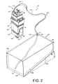
- Fig. 2 is a diagram showing some parts of this printer in greater detail.
- Example 1 indicates the sensitivity of various materials to disintegration in carbon-containing ink and the clogging of flexible hoses made of these materials.
- Example 2 indicates the permeability of flexible hoses of the various types of material to air and water.
- Example 3 relates to the flexibility of a number of materials.
- Example 4 indicates how a flexible hose can be made from an alkylene alkyl-acrylate copolymer.
- Fig. 1 is a perspective view of an inkjet printer 102 provided with a guide surface 109 for guiding receiving material 106 and a number of printheads 112, which are shown in greater detail in Fig. 2.
- the printer 102 is also provided with a device 110 for transporting ink from reservoirs 114 to the printheads 112 for the continuous replenishment of ink in the printheads.
- the reservoirs 114 are carried by a support element 107.
- Each of the reservoirs 114 contains an ink sac 148.
- the apparatus comprises a set of connecting elements 116 which each extend from a first end 172 in an ink sac 148 via a flexible conductor 108 to a second end connected to a printhead 112.
- Each of the elements 116 is provided with a valve 118 by means of which the ink flow can be shut off and re-opened.
- the printheads 112 are carried by a scanning carriage 105. Since the support element 107 is at a level lower than that of the scanning carriage 105, there is a small negative pressure acting on each of the printheads 112 if the valve 118 is open. This prevents the fluid ink from running out of the printheads 112 of itself and soiling the receiving material 106.
- the scanning carriage 105 moves laterally over a guide system with respect to the horizontally oriented receiving material 106.
- Each of the printheads comprises a plurality of print elements (not shown), from which individual ink drops are jetted on to the receiving material.
- a strip of the receiving material of a width of a printhead is printed in one or more passes.
- the receiving material is then advanced in a transit direction of the printers so that a following strip can be printed.
- a negative pressure is generated in each of the printheads as a result of the jetting of ink. This negative pressure is greater than the hydrodynamic vacuum as a result of the difference in levels between the scanning carriage 105 and the support element 107.
- ink will be practically continuously sucked through the printheads 112 from the ink reservoirs 114 via the connecting elements 116.
- Fig. 2 is a diagram showing a number of parts of the printer in greater detail, and particularly the apparatus for conveying the ink.
- the printhead 112 comprises an ink holder 124, provided with a top part 126, a base 128, a front 130, a rear 132 and two side surfaces 134.
- At the front 130 of the printhead 112 it is just possible to see a part of printing unit 122, which is mostly situated at the bottom of the printhead.
- This print unit is provided with a large number of internal fine ink ducts (not shown), which have a typical diameter of 10 - 40 ⁇ m. Each of the ducts is in contact with ink situated in the ink holder 124.
- each duct terminates at the bottom 128 in a nozzle (not shown), through which nozzle ink drops can be jetted in the direction of guide surface 109.
- each duct is provided with means (not shown) for suddenly greatly increasing the pressure in the duct so that a drop of ink is jetted at the front from the corresponding duct. These means are actuated via contacts 136.
- the printhead 112 is in contact with ink reservoir 114 via a connecting element 116.
- the reservoir 114 is a substantially rectangular box with a base 138, a top 140, a small reservoir end 142, a large reservoir end 114 and opposite reservoir sides 146.
- the reservoir sides 146 are trapezoidal in shape because the reservoir base 138 extends obliquely upwards from the reservoir end 144 to the smaller reservoir end 142. Since the reservoir base extends up over a small angle of typically 10°, provision is made for the ink contained in the reservoir to be practically completely sucked up by the printhead 112. This provides the user with a saving in ink consumption.
- the connecting element 116 between the printhead 112 and the reservoir 114 in this embodiment contains a deformable but substantially rigid tube 146, a flexible hose 160 and a connecting member 166.
- the tube 162 is introduced into the ink holder 124 via a passage hole 127 in the top 126 and extends in the ink holder 124 as far as the vicinity of the bottom 128.
- the tube 162 is connected to flexible hose 160.
- the hose has one end 172 terminating in the low-level part of the reservoir 114.
- the hose 160 enters the reservoir via an opening 171 therein.
- the hose is provided with means for relieving tension by fixing it practically directly behind the opening 171 to a ring 173 which is permanently connected to the reservoir wall 142.
- the hose 162 will remain in the reservoir without any internal tension, even when the scanning carriage 105 moves in reciprocation with respect to the printer guide surface 109.
- ink will be jetted from the nozzles of the print unit 122. This results in a negative pressure in the corresponding ink ducts. Since these ducts communicate with the ink in ink holder 124, ink in the ink holder 124 will be sucked in by this negative pressure. This results in a vacuum in the ink holder. Since the latter in turn, however, communicates with ink reservoir 114 via connecting member 116, ink will be sucked in from the reservoir 114. In this way, the quantity of ink in the ink holder 124 is always at a functional level.
- hoses made from these materials were subjected to the following test. A homogeneous hose was taken from each material with an internal diameter of about half a centimetre. From this, a piece approximately 10 cm long was cut off. Each piece of hose was then placed in a dish and immersed in Lexmark Black ink, a carbon-pigmented ink. The pieces of hose were kept in this for a period of 8 months at a constant temperature of 40°C. After 8 months, the pieces of hose were removed from the ink. Each piece of hose was then checked to see whether any clogging had occurred in the hose.
- Table 1 indicates that nine different types of PVC (polyvinylchloride) were tested. This material is frequently used because it is practically impermeable to gases and water. The first two PVC materials are made by Meldon, and then PVC materials were tested from RIA, Glasmag and Tygon. It was found that all these materials give rise to clogging of the hose with clotted and/or gelled ink. In addition, all the materials show a weight change of more than 1%, even the Pharma grade (S-50-HL) and Food & Drink grade (B-44-3) of Tygon. This indicates that these materials are basically not resistant to the carbon-containing ink.
- PVC polyvinylchloride
- the Viton rubber which also has the disadvantage that it is not transparent and very expensive, showed a mass change of 1.62%, in this case an increase in mass.
- this fluorine rubber is not resistant to the carbon-containing ink but absorbs a considerable amount of water. Due to this swelling, the permeability to water, which is initially practically zero, has been found to rise sharply.
- EMA is a copolymer of ethylene and methylacrylate. Hoses of this material are not available commercially, so that the applicants themselves made a hose of this material as indicated below in Example 4.
- this material is substantially resistant to the carbon-containing ink because the mass change was only 0.5%. In addition, there is no clogging of the hose. Nor could any perceptible change be found in mechanical properties in the handling of the hose after the termination of the test.
- This example indicates how permeable hoses of the various types of material are to oxygen.
- Table 2 gives the permeability coefficient to oxygen for various materials. This coefficient is a good indication of permeability to gas generally and air in particular. A low permeability to air is important for use with a material as a hose for the transport of ink in inkjet printers.
- the PVC materials of the type indicated in Example 1 have a relatively low permeability coefficient which makes them practically impermeable to air.
- Fluorine-containing materials such as Viton rubber and Teflon pass scarcely any perceptible quantity of oxygen through and can accordingly be regarded as impermeable to air.
- Polythene materials however, appear very permeable to oxygen and consequently also to air. This makes materials of this kind much less suitable for use as a hose for conveying ink.
- permeability coefficients were also determined for alkylene alkyl-acrylate copolymers, at least of the copolymers according to one embodiment of the invention. These were found to have an oxygen permeability comparable to that of the PVC materials. This means that these copolymers are practically impermeable to air and hence very suitable for forming hoses for the transport of ink.
- the permeability of the various materials to water can be determined as indicated in WO 98/31546. It has been found that PE materials have a scarcely measurable permeability to water. PVC passes somewhat more water but can also be regarded as practically impermeable to water (hence PVC, which as indicated hereinbefore is also practically impermeable to air, is often used for making rubber boats and the like).
- the tested fluorine-containing materials as indicated in Example 1 are also practically impermeable to water. As indicated hereinbefore, fluorine rubbers, however, lose their impermeability to water in the case of longterm use.
- the alkylene alkyl-acrylate copolymers according to one embodiment of the invention were also found to be practically impermeable to water.
- This example deals with the flexibility of a number of materials.
- numerous and often empirical measurements are known from the prior art.
- the E-modulus in turn depends on the hardness of the material.
- an indirect measure of flexibility can be obtained by measuring the hardness of the material.
- the harder a material the less flexible that material is.
- a harder material is often more sensitive to kinking.
- Hardnesses of rubber materials can be measured in accordance with DIN Standard D2240 and are expressed in Shore-A. It has been found that PVC materials of the type as indicated under Example 1 have a low hardness, typically lower than 200, and preferably lower than 100 Shore-A, and can be termed flexible. Polythene and particularly Viton are also flexible because their hardness is typically lower than the above values. All these materials have also been found to be practically insensitive to kinking. Teflon, on the other hand, is so hard that its hardness cannot be given in Shore-A but is expressed in Shore-D (a typical hardness of Teflon is 60 Shore-D), and this means that this material is factors harder. Hoses made from this material are accordingly not flexible and also very sensitive to kinking. Alkylene alkyl-acrylate copolymers according to one embodiment of the invention really are flexible. EMA in particular is very flexible and practically insensitive to kinking. The hardness of EMA rubber measured in accordance with the above Standard is about 78 Shore-A.
- alkylene alkyl-acrylate copolymers according to the invention have a high MFI, it has been found that they can be very well processed to form hoses by extrusion. It is also a simple matter to make multi-layer hoses with this material, for example a hose with an inner wall of an alkylene alkyl-acrylate copolymer and one or more following layers of any material, depending on any additional requirements.
- extruder speed and throughput were then so selected as to give a transparent smooth and shiny hose.
- the optimum speed, throughput and temperature differs per batch of raw material, and can readily be found by trial and error by the skilled man.
Landscapes
- Ink Jet (AREA)
- Rigid Pipes And Flexible Pipes (AREA)
Abstract
Description
- The invention relates to an apparatus for transporting fluid ink from an ink reservoir to a printhead, comprising a flexible hose for transporting the ink, which hose has a wall which during the transport of the ink is in contact with the ink, which wall is of a material which is impermeable or almost impermeable to water and air. The invention also relates to a hose suitable for transporting fluid ink and the use of such a hose for transporting fluid ink.
- An apparatus of this kind is known from US 6 003 981. From this patent specification is known to use the said apparatus in a large format inkjet printer. In this printer, a number of printheads carried on a scanning carriage are provided with aqueous ink, the ink being fed from an equal number of reservoirs by means of a number of flexible hoses. By using hoses of sufficient length it is possible to provide ink to the printheads even during printing, during which the printheads are constantly moved with respect to a receiving material being printed. In this way printing need never be interrupted to add ink to the printheads.
- From the patent specification it is known that the hoses have a number of properties making them suitable for the described use. The hoses are impermeable or practically impermeable to water (water vapour in this case) and to air. If they are permeable to water, then the ink will lose some of its water through the wall of the hose so that the ink properties change. The ink becomes more viscous because it is more difficult to jet and there is also a risk of clogging of fine nozzles with which the ink is finally jetted from the printhead. Permeability to air can result in too much air being absorbed (or any gas or mixture of gases whatsoever in the printer environment) by the ink. This can also affect print quality or even result in breakdown of printing elements (which often contain fine ink ducts in the printhead). In addition, through the absorption of air from the environment, it is difficult to maintain a negative pressure in the ink supply system, and this is necessary in order to avoid ink leakage at the front of the print head. In addition to this substantial impermeability to water and air, the hoses must be flexible, i.e. their modulus must be sufficiently small since otherwise excessive forces would be exerted on the scanning carriage. In addition, the sensitivity to kinking is relatively considerable in the hoses which are not flexible. Kinking is undesirable because as a result the ink supply through the associated hose experiences too greater a resistance. Finally, the hoses are preferably durable so that they will retain all these properties for a long time, typically corresponding to some hundreds of thousands and even millions of passes of the scanning carriage. According to the patent specification, for this purpose hoses are used which are made of polyvinylidene-chloride copolymer (PVDC). Such materials, which typically contain 80% vinylidene chloride monomer and 20% vinyl chloride monomer meet the above requirements. However, when such hoses are used, it has been found that the printheads at the front, i.e. the side where the ink is jetted, become very soiled with ink after long and intensive use. Such soiling has a negative influence on the print quality, on the one hand because the jetting of the ink is influenced by the presence of soiling around the nozzles, and on the other hand because ink could drip unwantedly on to the receiving material for printing. It has also been found that when the ink is stationary in the hoses for a long period intensive clotting or thickening of the ink occurs in the hoses despite the fact that the wall of the hose is substantially impermeable to water. Such clotting or thickening results in clogging of the hose and accordingly breakdown of the corresponding printheads. These effects are present particularly when black ink is used.
- The object of the invention is to provide an apparatus which, even with long and intensive use, does not result in intensive soiling of the front of the printhead and wherein the hoses do not clog, even if ink is stationary therein for long periods. To this end, an apparatus according to the preamble of claim 1 has been invented which is characterised in that the said material is substantially resistant to carbon-containing ink.
- It has surprisingly been found that a hose according to this invention does not result in soiling of the front of the printhead and that the ink, even if it is stationary in the hose for a long period, does not show any clotting or thickening such that the hose containing this ink clogs. The reason for this is not completely clear, but it would appear that in the known hoses an at least partial disintegration, chemical and/or physical, of the material takes place in the presence of carbon particles (which are frequently used as black pigment) in the ink. The probable cause is that disintegration products or specific components from the material of which the hose is made occupy the front of the printhead so that this can be more readily wetted by ink and can hence soil considerably. The clotting or thickening of the ink is possibly a result of a gelling process because, despite the non-evaporation of water through the wall of the hose, a considerable thickening of the ink nevertheless occurs. Possibly one or more disintegration products or other substances originating from the material of the hose act as a gelling agent in the ink. With the use of an apparatus in which the material is resistant to a carbon-containing ink, i.e. the material experiences no substantial change when in contact with such an ink for a long period, these problems do not occur or occur at least less rapidly, under the above circumstances. The skilled man can readily determine whether a material experiences a substantial change. For this purpose, he can for example determine the mechanical properties and/or the composition of the material, either quantitatively or qualitatively, before and after an exposure to ink for a long period, for example some months up to a year. If the properties have not substantially changed, then it is a material according to the invention and with it an apparatus according to the invention can be obtained. Furthermore, it is immaterial to the invention whether the material is homogeneous, a blend, a composite, or of no matter what consistency.
- It is also known from WO 98/31546 to use hoses of which at least the inner wall is made of polythene or polytetrafluoroethylene (Teflon). Polythene materials are substantially impermeable to water, water vapour in this case, but they have been found to be relatively highly permeable to air or other gases. Consequently such hoses do not meet the requirements for high-grade use. The hoses made of Teflon are in turn very stiff and hence not flexible. This restricts the possible applications of such hoses. They are therefore even further away from the invention than the above-described hoses.
- In one embodiment, the material is an alkylene alkyl-acrylate copolymer, wherein the alkylene is selected from the group consisting of ethylene and propylene and the alkyl-acrylate is selected from the group consisting of methyl, ethyl, propyl and butyl acrylate. It has been found that a material of this kind can be used in an apparatus according to the invention because this material has been found to be resistant to carbon-containing inks. Even with very long exposure to such ink, the material exhibits no perceptible change in properties or composition. Also, it has been found that this material can be easily processed to form hoses, for example by extrusion. This is surprising because the high melt flow index (MFI) of such acrylate copolymers would lead one to expect that this material would be difficult to process, if it could be processed at all, in such a process.
- In another embodiment, the material is a copolymer of ethylene with the said alkyl-acrylate. With a copolymer of this kind it is possible to make a hose which is even more flexible and has less tendency to kinking so that the risk of the hose being shut off is further reduced. Also, this material is relatively cheap.
- In another embodiment, the alkyl-acrylate is selected from the group consisting of methyl and ethyl acrylate. Such copolymers are very flexible and pass even less water than the propyl and butyl acrylates. In this way the apparatus according to the invention can be further improved. In a preferred embodiment, the copolymer is an ethylene methyl acrylate. It has been found that such a copolymer is the most flexible and that the water and air permeability are minimised. The resistance to carbon is also good.
- The invention will now be explained in detail with reference to the following Figures and examples.
- Fig. 1 is a diagram of an inkjet printer provided with a device for conveying ink from reservoirs to the printheads (prior art).
- Fig. 2 is a diagram showing some parts of this printer in greater detail.
- Example 1 indicates the sensitivity of various materials to disintegration in carbon-containing ink and the clogging of flexible hoses made of these materials.
Example 2 indicates the permeability of flexible hoses of the various types of material to air and water.
Example 3 relates to the flexibility of a number of materials.
Example 4 indicates how a flexible hose can be made from an alkylene alkyl-acrylate copolymer. - Fig. 1 is a perspective view of an
inkjet printer 102 provided with aguide surface 109 for guiding receivingmaterial 106 and a number ofprintheads 112, which are shown in greater detail in Fig. 2. Theprinter 102 is also provided with adevice 110 for transporting ink fromreservoirs 114 to theprintheads 112 for the continuous replenishment of ink in the printheads. Thereservoirs 114 are carried by asupport element 107. Each of thereservoirs 114 contains anink sac 148. The apparatus comprises a set of connectingelements 116 which each extend from afirst end 172 in anink sac 148 via aflexible conductor 108 to a second end connected to aprinthead 112. Each of theelements 116 is provided with avalve 118 by means of which the ink flow can be shut off and re-opened. Theprintheads 112 are carried by ascanning carriage 105. Since thesupport element 107 is at a level lower than that of thescanning carriage 105, there is a small negative pressure acting on each of theprintheads 112 if thevalve 118 is open. This prevents the fluid ink from running out of theprintheads 112 of itself and soiling the receivingmaterial 106. During the printing of receivingmaterial 106, for example a sheet of paper, thescanning carriage 105 moves laterally over a guide system with respect to the horizontally oriented receivingmaterial 106. Each of the printheads comprises a plurality of print elements (not shown), from which individual ink drops are jetted on to the receiving material. In this way, a strip of the receiving material of a width of a printhead is printed in one or more passes. The receiving material is then advanced in a transit direction of the printers so that a following strip can be printed.
During printing, a negative pressure is generated in each of the printheads as a result of the jetting of ink. This negative pressure is greater than the hydrodynamic vacuum as a result of the difference in levels between the scanningcarriage 105 and thesupport element 107. As a result, ink will be practically continuously sucked through theprintheads 112 from theink reservoirs 114 via the connectingelements 116. In this way, there is no need to interrupt printing, even if large-format images have to be printed for a long time, despite the fact that theprintheads 112 as such have only a low ink capacity (typically some tens of cc's). As a result of the continuous supply of ink fromreservoirs 114, which contain a quantity of ink of typically 500 to 1000 cc, the heads can for a long time be provided with fluid ink without any need to add ink. - Fig. 2 is a diagram showing a number of parts of the printer in greater detail, and particularly the apparatus for conveying the ink. In this embodiment, the
printhead 112 comprises anink holder 124, provided with atop part 126, abase 128, a front 130, a rear 132 and two side surfaces 134. At thefront 130 of theprinthead 112 it is just possible to see a part ofprinting unit 122, which is mostly situated at the bottom of the printhead. This print unit is provided with a large number of internal fine ink ducts (not shown), which have a typical diameter of 10 - 40 µm. Each of the ducts is in contact with ink situated in theink holder 124. Each duct terminates at the bottom 128 in a nozzle (not shown), through which nozzle ink drops can be jetted in the direction ofguide surface 109. For this purpose, each duct is provided with means (not shown) for suddenly greatly increasing the pressure in the duct so that a drop of ink is jetted at the front from the corresponding duct. These means are actuated viacontacts 136. As described hereinbefore, theprinthead 112 is in contact withink reservoir 114 via a connectingelement 116. In this embodiment, thereservoir 114 is a substantially rectangular box with abase 138, a top 140, a small reservoir end 142, alarge reservoir end 114 and opposite reservoir sides 146. The reservoir sides 146 are trapezoidal in shape because thereservoir base 138 extends obliquely upwards from thereservoir end 144 to the smaller reservoir end 142. Since the reservoir base extends up over a small angle of typically 10°, provision is made for the ink contained in the reservoir to be practically completely sucked up by theprinthead 112. This provides the user with a saving in ink consumption. The connectingelement 116 between theprinthead 112 and thereservoir 114 in this embodiment contains a deformable but substantiallyrigid tube 146, aflexible hose 160 and a connecting member 166. At the rear 132 ofink holder 112 the tube 162 is introduced into theink holder 124 via apassage hole 127 in the top 126 and extends in theink holder 124 as far as the vicinity of the bottom 128. Via the connecting member 166 the tube 162 is connected toflexible hose 160. It is a flexible hose of this kind to which the invention relates. The hose has oneend 172 terminating in the low-level part of thereservoir 114. Thehose 160 enters the reservoir via anopening 171 therein. The hose is provided with means for relieving tension by fixing it practically directly behind theopening 171 to aring 173 which is permanently connected to the reservoir wall 142. As a result, the hose 162 will remain in the reservoir without any internal tension, even when thescanning carriage 105 moves in reciprocation with respect to theprinter guide surface 109.
During printing, ink will be jetted from the nozzles of theprint unit 122. This results in a negative pressure in the corresponding ink ducts. Since these ducts communicate with the ink inink holder 124, ink in theink holder 124 will be sucked in by this negative pressure. This results in a vacuum in the ink holder. Since the latter in turn, however, communicates withink reservoir 114 via connectingmember 116, ink will be sucked in from thereservoir 114. In this way, the quantity of ink in theink holder 124 is always at a functional level. - This example indicates the sensitivity of various materials to disintegration in carbon-containing ink and the clogging of hoses made from these materials.
For this purpose, hoses made from these materials were subjected to the following test. A homogeneous hose was taken from each material with an internal diameter of about half a centimetre. From this, a piece approximately 10 cm long was cut off. Each piece of hose was then placed in a dish and immersed in Lexmark Black ink, a carbon-pigmented ink. The pieces of hose were kept in this for a period of 8 months at a constant temperature of 40°C. After 8 months, the pieces of hose were removed from the ink. Each piece of hose was then checked to see whether any clogging had occurred in the hose. The pieces of hose were then cleaned and dried and the nett mass change was determined. This mass change is an index of the resistance of the hose to the carbon-containing ink. Table 1 shows the findings and measurements.Sensitivity of various materials to disintegration in carbon-containing ink and the clogging of hoses made from these materials. Mark Type Material Mass change (%) Clogging Meldon 5469125 PVC - 1,42 Yes Meldon 5369007 PVC - 2,29 Yes RIA PVC PVC - 9,08 Yes Glasmag 2,4/4,0 PVC - 6,65 Yes Tygon F-4040-A PVC - 1,27 Yes Tygon S-50-HL PVC - 2,58 Yes Tygon R-3603 PVC - 2,71 Yes Tygon R-1000 PVC - 1,79 Yes Tygon B-44-3 PVC -2,11 Yes Fischer PE-flex PE + 0,60 No Tygon 2075 PE + 0,46 No RIA TPE PE + 0,30 No Parker PE-flex PE + 0,34 No Fluran Viton fluorine rubber + 1,62 No Nitto PTFE Teflon 0 No - - EMA + 0,50 No - Table 1 indicates that nine different types of PVC (polyvinylchloride) were tested. This material is frequently used because it is practically impermeable to gases and water. The first two PVC materials are made by Meldon, and then PVC materials were tested from RIA, Glasmag and Tygon. It was found that all these materials give rise to clogging of the hose with clotted and/or gelled ink. In addition, all the materials show a weight change of more than 1%, even the Pharma grade (S-50-HL) and Food & Drink grade (B-44-3) of Tygon. This indicates that these materials are basically not resistant to the carbon-containing ink. In the handling of the PVC hoses it was also found that they had acquired different mechanical properties due to the long-term exposure to the ink. Their flexibility had fallen off to some extent and the sensitivity to kinking was increased. In addition, four PE (polythene) materials were tested in this way. None of these materials showed any clogging of the hose and in addition they were found to be substantially resistant to the carbon-containing ink because the mass change was less than 1%.
The two fluorine-containing materials (Viton and Teflon) did not show any clogging of the hoses. In addition, Teflon appears to be completely inert under these conditions, and no mass change whatever was found. On the other hand, the Viton rubber, which also has the disadvantage that it is not transparent and very expensive, showed a mass change of 1.62%, in this case an increase in mass. Apparently this fluorine rubber is not resistant to the carbon-containing ink but absorbs a considerable amount of water. Due to this swelling, the permeability to water, which is initially practically zero, has been found to rise sharply. This is a significant disadvantage for the use of a hose of this kind for conveying ink.
The last material tested (EMA) is a copolymer of ethylene and methylacrylate. Hoses of this material are not available commercially, so that the applicants themselves made a hose of this material as indicated below in Example 4. It was found that this material is substantially resistant to the carbon-containing ink because the mass change was only 0.5%. In addition, there is no clogging of the hose. Nor could any perceptible change be found in mechanical properties in the handling of the hose after the termination of the test. - This example indicates how permeable hoses of the various types of material are to oxygen. For this purpose, Table 2 gives the permeability coefficient to oxygen for various materials. This coefficient is a good indication of permeability to gas generally and air in particular. A low permeability to air is important for use with a material as a hose for the transport of ink in inkjet printers.
The permeability coefficient as indicated can be determined by connecting the hose to an oxygen pipe and then shutting it off. The coefficient can now be calculated by measuring the quantity of oxygen passing through the wall of the hose during a certain period of time, at a certain oxygen pressure in the hose. The permeability coefficient can then be calculated in accordance with formula I - PC =
- permeability coefficient [cm2/s cmHg]
- V =
- quantity of diffused gas [cm3]
- d =
- thickness of the hose wall [cm]
- A =
- area of the hose wall [cm2]
- t =
- measuring time [sec]
- Δp =
- pressure drop over the hose wall [cmHg]
- It will be apparent from Table 2 that the PVC materials of the type indicated in Example 1 have a relatively low permeability coefficient which makes them practically impermeable to air. Fluorine-containing materials such as Viton rubber and Teflon pass scarcely any perceptible quantity of oxygen through and can accordingly be regarded as impermeable to air. Polythene materials, however, appear very permeable to oxygen and consequently also to air. This makes materials of this kind much less suitable for use as a hose for conveying ink. Finally, permeability coefficients were also determined for alkylene alkyl-acrylate copolymers, at least of the copolymers according to one embodiment of the invention. These were found to have an oxygen permeability comparable to that of the PVC materials. This means that these copolymers are practically impermeable to air and hence very suitable for forming hoses for the transport of ink.
- The permeability of the various materials to water can be determined as indicated in WO 98/31546. It has been found that PE materials have a scarcely measurable permeability to water. PVC passes somewhat more water but can also be regarded as practically impermeable to water (hence PVC, which as indicated hereinbefore is also practically impermeable to air, is often used for making rubber boats and the like). The tested fluorine-containing materials as indicated in Example 1 are also practically impermeable to water. As indicated hereinbefore, fluorine rubbers, however, lose their impermeability to water in the case of longterm use. The alkylene alkyl-acrylate copolymers according to one embodiment of the invention were also found to be practically impermeable to water.
- This example deals with the flexibility of a number of materials. To quantify the flexibility of a material, numerous and often empirical measurements are known from the prior art. However, it has been found that the flexibility of a material is well correlated to the E-modulus of the material. The E-modulus in turn depends on the hardness of the material. In this way, an indirect measure of flexibility can be obtained by measuring the hardness of the material. Generally, the harder a material, the less flexible that material is. Also, a harder material is often more sensitive to kinking. For use as a transport hose in an inkjet printer a flexible hose is desirable.
- Hardnesses of rubber materials can be measured in accordance with DIN Standard D2240 and are expressed in Shore-A. It has been found that PVC materials of the type as indicated under Example 1 have a low hardness, typically lower than 200, and preferably lower than 100 Shore-A, and can be termed flexible. Polythene and particularly Viton are also flexible because their hardness is typically lower than the above values. All these materials have also been found to be practically insensitive to kinking. Teflon, on the other hand, is so hard that its hardness cannot be given in Shore-A but is expressed in Shore-D (a typical hardness of Teflon is 60 Shore-D), and this means that this material is factors harder. Hoses made from this material are accordingly not flexible and also very sensitive to kinking. Alkylene alkyl-acrylate copolymers according to one embodiment of the invention really are flexible. EMA in particular is very flexible and practically insensitive to kinking. The hardness of EMA rubber measured in accordance with the above Standard is about 78 Shore-A.
- Despite the fact that the alkylene alkyl-acrylate copolymers according to the invention have a high MFI, it has been found that they can be very well processed to form hoses by extrusion. It is also a simple matter to make multi-layer hoses with this material, for example a hose with an inner wall of an alkylene alkyl-acrylate copolymer and one or more following layers of any material, depending on any additional requirements.
- The Applicants have made hoses of ethylene methyl-acrylate OE 5625 (Elvaloy) of DuPont in an AXXON laboratory extruder, type B25, single screw. The following settings were used for this:
- zone 1 : 225°C
- zone 2 : 215°C
- zone 3 : 200°C
- zone 4 : 185°C
- zone 5 : 155°C
- The extruder speed and throughput were then so selected as to give a transparent smooth and shiny hose. The optimum speed, throughput and temperature differs per batch of raw material, and can readily be found by trial and error by the skilled man.
| Order of magnitude of permeability coefficient for various types of material with respect to oxygen. | |
| Type of material | PC x 10-11 [cm2/s cm Hg] |
| PVC | 20 - 250 |
| Fluorine-containing | 10 - 15 |
| PE | > 1000 |
| Alkylene alkyl-acrylate copolymer | 50 - 250 |
Claims (11)
- An apparatus for transporting fluid ink from an ink reservoir to a printhead, comprising a flexible hose for transporting the ink, which hose has a wall which during the transport of the ink is in contact with the ink, which wall is of a material which is impermeable or almost impermeable to water and air, characterised in that the said material is substantially resistant to carbon-containing ink.
- An apparatus according to claim 1, characterised in that the material is an alkylene alkyl-acrylate copolymer, wherein the alkylene is selected from the group consisting of ethylene and propylene and the alkyl-acrylate is selected from the group consisting of methyl, ethyl, propyl and butyl acrylate.
- An apparatus according to claim 2, characterised in that the material is a copolymer of ethylene and the alkyl-acrylate.
- An apparatus according to claim 2 or 3, characterised in that the alkyl-acrylate is selected from the group consisting of methyl and ethyl acrylate.
- An apparatus according to claim 4, characterised in that the alkyl-acrylate is methyl acrylate.
- A flexible hose suitable for transporting fluid ink, which hose has a wall which, if ink is transported through the house, is in contact with the ink, which wall is of a material which is impermeable or almost impermeable to water and air, characterised in that the said material is substantially resistant to carbon-containing ink.
- A flexible hose according to claim 6, characterised in that the material is an alkylene alkyl-acrylate copolymer, wherein the alkylene is selected from the group consisting of ethylene and propylene and the alkyl-acrylate is selected from the group consisting of methyl, ethyl, propyl and butyl acrylate.
- A flexible hose according to claim 7, characterised in that the material is a copolymer of ethylene and the alkyl acrylate.
- A flexible hose according to claim 7 or 8, characterised in that the alkyl-acrylate is selected from the group consisting of methyl and ethyl acrylate.
- A flexible hose according to claim 9, characterised in that the alkyl acrylate is methyl acrylate.
- Use of the flexible hose according to any one of claims 6 to 10 for the transporting of fluid ink.
Applications Claiming Priority (2)
| Application Number | Priority Date | Filing Date | Title |
|---|---|---|---|
| NL1018564A NL1018564C2 (en) | 2001-07-17 | 2001-07-17 | A device for transporting liquid ink, a flexible hose suitable for such a device and the use of such a hose. |
| NL1018564 | 2001-07-17 |
Publications (2)
| Publication Number | Publication Date |
|---|---|
| EP1277585A1 true EP1277585A1 (en) | 2003-01-22 |
| EP1277585B1 EP1277585B1 (en) | 2006-10-11 |
Family
ID=19773740
Family Applications (1)
| Application Number | Title | Priority Date | Filing Date |
|---|---|---|---|
| EP02077778A Expired - Lifetime EP1277585B1 (en) | 2001-07-17 | 2002-07-01 | An apparatus for transporting fluid ink, a flexible hose suitable for such apparatus, and the use of such a hose |
Country Status (5)
| Country | Link |
|---|---|
| US (1) | US6726314B2 (en) |
| EP (1) | EP1277585B1 (en) |
| JP (1) | JP4344117B2 (en) |
| DE (1) | DE60215262T2 (en) |
| NL (1) | NL1018564C2 (en) |
Families Citing this family (4)
| Publication number | Priority date | Publication date | Assignee | Title |
|---|---|---|---|---|
| JP4160360B2 (en) * | 2002-10-28 | 2008-10-01 | 住友ゴム工業株式会社 | Ink tube for inkjet printer |
| US20080018717A1 (en) * | 2006-07-21 | 2008-01-24 | Hewlett-Packard Development Company Lp | Transfer station |
| US8783077B2 (en) * | 2009-11-17 | 2014-07-22 | Christopher Robert Sullivan | Portable truing device for spoked wheels and method of use |
| JP6056181B2 (en) * | 2012-04-26 | 2017-01-11 | セイコーエプソン株式会社 | Recording device |
Citations (8)
| Publication number | Priority date | Publication date | Assignee | Title |
|---|---|---|---|---|
| JPH02151674A (en) * | 1988-12-02 | 1990-06-11 | Seiko Epson Corp | Inkjet recording method |
| JPH0542680A (en) * | 1991-08-12 | 1993-02-23 | Fuji Xerox Co Ltd | Residual amount detector of ink tank |
| JPH0811480A (en) * | 1994-07-01 | 1996-01-16 | Tombow Pencil Co Ltd | Ink reservoir for liquid low viscosity ink writing instruments |
| EP0722835A1 (en) * | 1994-05-11 | 1996-07-24 | Seiko Epson Corporation | Ink jet recording method and recording apparatus |
| EP0778143A1 (en) * | 1995-12-04 | 1997-06-11 | Hewlett-Packard Company | Ink cartridge adapters |
| WO1998031546A1 (en) | 1997-01-21 | 1998-07-23 | Minnesota Mining And Manufacturing Company | Tubing for an ink delivery system |
| EP0956960A2 (en) * | 1998-04-29 | 1999-11-17 | Hewlett-Packard Company | Multi-chamber fluid supply |
| US6003981A (en) | 1996-08-30 | 1999-12-21 | Hewlett-Packard Company | Replaceable module for a printing composition delivery system of a printing device |
Family Cites Families (2)
| Publication number | Priority date | Publication date | Assignee | Title |
|---|---|---|---|---|
| US5796419A (en) | 1995-12-04 | 1998-08-18 | Hewlett-Packard Company | Self-sealing fluid interconnect |
| US5988801A (en) * | 1996-09-30 | 1999-11-23 | Hewlett-Packard Company | High performance tubing for inkjet printing systems with off-board ink supply |
-
2001
- 2001-07-17 NL NL1018564A patent/NL1018564C2/en not_active IP Right Cessation
-
2002
- 2002-07-01 DE DE60215262T patent/DE60215262T2/en not_active Expired - Lifetime
- 2002-07-01 EP EP02077778A patent/EP1277585B1/en not_active Expired - Lifetime
- 2002-07-03 JP JP2002194269A patent/JP4344117B2/en not_active Expired - Fee Related
- 2002-07-17 US US10/196,178 patent/US6726314B2/en not_active Expired - Lifetime
Patent Citations (8)
| Publication number | Priority date | Publication date | Assignee | Title |
|---|---|---|---|---|
| JPH02151674A (en) * | 1988-12-02 | 1990-06-11 | Seiko Epson Corp | Inkjet recording method |
| JPH0542680A (en) * | 1991-08-12 | 1993-02-23 | Fuji Xerox Co Ltd | Residual amount detector of ink tank |
| EP0722835A1 (en) * | 1994-05-11 | 1996-07-24 | Seiko Epson Corporation | Ink jet recording method and recording apparatus |
| JPH0811480A (en) * | 1994-07-01 | 1996-01-16 | Tombow Pencil Co Ltd | Ink reservoir for liquid low viscosity ink writing instruments |
| EP0778143A1 (en) * | 1995-12-04 | 1997-06-11 | Hewlett-Packard Company | Ink cartridge adapters |
| US6003981A (en) | 1996-08-30 | 1999-12-21 | Hewlett-Packard Company | Replaceable module for a printing composition delivery system of a printing device |
| WO1998031546A1 (en) | 1997-01-21 | 1998-07-23 | Minnesota Mining And Manufacturing Company | Tubing for an ink delivery system |
| EP0956960A2 (en) * | 1998-04-29 | 1999-11-17 | Hewlett-Packard Company | Multi-chamber fluid supply |
Non-Patent Citations (3)
| Title |
|---|
| PATENT ABSTRACTS OF JAPAN vol. 014, no. 403 (C - 0753) 31 August 1990 (1990-08-31) * |
| PATENT ABSTRACTS OF JAPAN vol. 017, no. 336 (M - 1435) 25 June 1993 (1993-06-25) * |
| PATENT ABSTRACTS OF JAPAN vol. 1996, no. 05 31 May 1996 (1996-05-31) * |
Also Published As
| Publication number | Publication date |
|---|---|
| EP1277585B1 (en) | 2006-10-11 |
| DE60215262D1 (en) | 2006-11-23 |
| JP2003039702A (en) | 2003-02-13 |
| DE60215262T2 (en) | 2007-09-06 |
| US6726314B2 (en) | 2004-04-27 |
| JP4344117B2 (en) | 2009-10-14 |
| NL1018564C2 (en) | 2003-01-20 |
| US20030025772A1 (en) | 2003-02-06 |
Similar Documents
| Publication | Publication Date | Title |
|---|---|---|
| US6164766A (en) | Automatic ink refill system for disposable ink jet cartridges | |
| US8337002B2 (en) | Ink ejection head unit and image forming apparatus | |
| EP0493058B1 (en) | Method and apparatus for supplying ink to an ink jet printer | |
| US6623092B2 (en) | Ink cartridge with separate magnets | |
| US7300138B2 (en) | Replaceable ink container for inkjet printer | |
| US8480213B2 (en) | Liquid containing tank, liquid-jet head unit, and image forming apparatus | |
| GB2282993A (en) | Disposable ink jet cartridge with an automatic refill system | |
| US20050151801A1 (en) | Ink delivery system apparatus and method | |
| US7165833B2 (en) | Ink container installation and alignment feature | |
| KR100607191B1 (en) | Image forming apparatus, recording liquid, conveyor belt, recording liquid cartridge | |
| US6726314B2 (en) | Apparatus for transporting fluid ink, and a flexible hose suitable for such transportation apparatus | |
| CN100417526C (en) | Medium conveying device and recording apparatus | |
| US10479089B2 (en) | Supply liquid tank unit and ink jet recording apparatus including the same | |
| US20050099470A1 (en) | Ink jet printer | |
| US6302503B1 (en) | Inkjet ink level detection | |
| US6971741B2 (en) | Liquid storage container | |
| EP0953450B1 (en) | Inkjet ink level detection | |
| JP2707658B2 (en) | Inkjet recording method | |
| CN111565934A (en) | Cans for Print Cartridges | |
| JP5412836B2 (en) | Image forming apparatus | |
| CN216986412U (en) | Novel coating liquid defoaming device | |
| US7314275B2 (en) | Recording liquid, liquid cartridge, liquid discharge apparatus and method of liquid discharge | |
| JP7687492B2 (en) | system | |
| KR101070010B1 (en) | Inkjet head assembly | |
| JP2018065364A (en) | Ink bottle |
Legal Events
| Date | Code | Title | Description |
|---|---|---|---|
| PUAI | Public reference made under article 153(3) epc to a published international application that has entered the european phase |
Free format text: ORIGINAL CODE: 0009012 |
|
| AK | Designated contracting states |
Kind code of ref document: A1 Designated state(s): AT BE BG CH CY CZ DE DK EE ES FI FR GB GR IE IT LI LU MC NL PT SE SK TR |
|
| AX | Request for extension of the european patent |
Free format text: AL;LT;LV;MK;RO;SI |
|
| 17P | Request for examination filed |
Effective date: 20030722 |
|
| AKX | Designation fees paid |
Designated state(s): DE FR GB NL |
|
| 17Q | First examination report despatched |
Effective date: 20031017 |
|
| GRAP | Despatch of communication of intention to grant a patent |
Free format text: ORIGINAL CODE: EPIDOSNIGR1 |
|
| GRAS | Grant fee paid |
Free format text: ORIGINAL CODE: EPIDOSNIGR3 |
|
| GRAA | (expected) grant |
Free format text: ORIGINAL CODE: 0009210 |
|
| AK | Designated contracting states |
Kind code of ref document: B1 Designated state(s): DE FR GB NL |
|
| REG | Reference to a national code |
Ref country code: GB Ref legal event code: FG4D |
|
| REF | Corresponds to: |
Ref document number: 60215262 Country of ref document: DE Date of ref document: 20061123 Kind code of ref document: P |
|
| ET | Fr: translation filed | ||
| PLBE | No opposition filed within time limit |
Free format text: ORIGINAL CODE: 0009261 |
|
| STAA | Information on the status of an ep patent application or granted ep patent |
Free format text: STATUS: NO OPPOSITION FILED WITHIN TIME LIMIT |
|
| 26N | No opposition filed |
Effective date: 20070712 |
|
| REG | Reference to a national code |
Ref country code: FR Ref legal event code: PLFP Year of fee payment: 15 |
|
| PGFP | Annual fee paid to national office [announced via postgrant information from national office to epo] |
Ref country code: NL Payment date: 20160708 Year of fee payment: 15 |
|
| PGFP | Annual fee paid to national office [announced via postgrant information from national office to epo] |
Ref country code: GB Payment date: 20160721 Year of fee payment: 15 Ref country code: DE Payment date: 20160722 Year of fee payment: 15 |
|
| PGFP | Annual fee paid to national office [announced via postgrant information from national office to epo] |
Ref country code: FR Payment date: 20160721 Year of fee payment: 15 |
|
| REG | Reference to a national code |
Ref country code: DE Ref legal event code: R119 Ref document number: 60215262 Country of ref document: DE |
|
| REG | Reference to a national code |
Ref country code: NL Ref legal event code: MM Effective date: 20170801 |
|
| GBPC | Gb: european patent ceased through non-payment of renewal fee |
Effective date: 20170701 |
|
| REG | Reference to a national code |
Ref country code: FR Ref legal event code: ST Effective date: 20180330 |
|
| PG25 | Lapsed in a contracting state [announced via postgrant information from national office to epo] |
Ref country code: DE Free format text: LAPSE BECAUSE OF NON-PAYMENT OF DUE FEES Effective date: 20180201 Ref country code: GB Free format text: LAPSE BECAUSE OF NON-PAYMENT OF DUE FEES Effective date: 20170701 Ref country code: NL Free format text: LAPSE BECAUSE OF NON-PAYMENT OF DUE FEES Effective date: 20170801 |
|
| PG25 | Lapsed in a contracting state [announced via postgrant information from national office to epo] |
Ref country code: FR Free format text: LAPSE BECAUSE OF NON-PAYMENT OF DUE FEES Effective date: 20170731 |