EP1277004B1 - Poppet valve seal - Google Patents
Poppet valve sealInfo
- Publication number
- EP1277004B1 EP1277004B1 EP01916818A EP01916818A EP1277004B1 EP 1277004 B1 EP1277004 B1 EP 1277004B1 EP 01916818 A EP01916818 A EP 01916818A EP 01916818 A EP01916818 A EP 01916818A EP 1277004 B1 EP1277004 B1 EP 1277004B1
- Authority
- EP
- European Patent Office
- Prior art keywords
- poppet valve
- seal according
- housing
- seal
- annular
- Prior art date
- Legal status (The legal status is an assumption and is not a legal conclusion. Google has not performed a legal analysis and makes no representation as to the accuracy of the status listed.)
- Expired - Lifetime
Links
Images



Classifications
-
- F—MECHANICAL ENGINEERING; LIGHTING; HEATING; WEAPONS; BLASTING
- F16—ENGINEERING ELEMENTS AND UNITS; GENERAL MEASURES FOR PRODUCING AND MAINTAINING EFFECTIVE FUNCTIONING OF MACHINES OR INSTALLATIONS; THERMAL INSULATION IN GENERAL
- F16K—VALVES; TAPS; COCKS; ACTUATING-FLOATS; DEVICES FOR VENTING OR AERATING
- F16K17/00—Safety valves; Equalising valves, e.g. pressure relief valves
-
- F—MECHANICAL ENGINEERING; LIGHTING; HEATING; WEAPONS; BLASTING
- F02—COMBUSTION ENGINES; HOT-GAS OR COMBUSTION-PRODUCT ENGINE PLANTS
- F02M—SUPPLYING COMBUSTION ENGINES IN GENERAL WITH COMBUSTIBLE MIXTURES OR CONSTITUENTS THEREOF
- F02M25/00—Engine-pertinent apparatus for adding non-fuel substances or small quantities of secondary fuel to combustion-air, main fuel or fuel-air mixture
- F02M25/08—Engine-pertinent apparatus for adding non-fuel substances or small quantities of secondary fuel to combustion-air, main fuel or fuel-air mixture adding fuel vapours drawn from engine fuel reservoir
- F02M25/0809—Judging failure of purge control system
-
- F—MECHANICAL ENGINEERING; LIGHTING; HEATING; WEAPONS; BLASTING
- F02—COMBUSTION ENGINES; HOT-GAS OR COMBUSTION-PRODUCT ENGINE PLANTS
- F02M—SUPPLYING COMBUSTION ENGINES IN GENERAL WITH COMBUSTIBLE MIXTURES OR CONSTITUENTS THEREOF
- F02M25/00—Engine-pertinent apparatus for adding non-fuel substances or small quantities of secondary fuel to combustion-air, main fuel or fuel-air mixture
- F02M25/08—Engine-pertinent apparatus for adding non-fuel substances or small quantities of secondary fuel to combustion-air, main fuel or fuel-air mixture adding fuel vapours drawn from engine fuel reservoir
- F02M25/0836—Arrangement of valves controlling the admission of fuel vapour to an engine, e.g. valve being disposed between fuel tank or absorption canister and intake manifold
-
- F—MECHANICAL ENGINEERING; LIGHTING; HEATING; WEAPONS; BLASTING
- F02—COMBUSTION ENGINES; HOT-GAS OR COMBUSTION-PRODUCT ENGINE PLANTS
- F02M—SUPPLYING COMBUSTION ENGINES IN GENERAL WITH COMBUSTIBLE MIXTURES OR CONSTITUENTS THEREOF
- F02M25/00—Engine-pertinent apparatus for adding non-fuel substances or small quantities of secondary fuel to combustion-air, main fuel or fuel-air mixture
- F02M25/08—Engine-pertinent apparatus for adding non-fuel substances or small quantities of secondary fuel to combustion-air, main fuel or fuel-air mixture adding fuel vapours drawn from engine fuel reservoir
- F02M25/0854—Details of the absorption canister
-
- F—MECHANICAL ENGINEERING; LIGHTING; HEATING; WEAPONS; BLASTING
- F16—ENGINEERING ELEMENTS AND UNITS; GENERAL MEASURES FOR PRODUCING AND MAINTAINING EFFECTIVE FUNCTIONING OF MACHINES OR INSTALLATIONS; THERMAL INSULATION IN GENERAL
- F16K—VALVES; TAPS; COCKS; ACTUATING-FLOATS; DEVICES FOR VENTING OR AERATING
- F16K1/00—Lift valves or globe valves, i.e. cut-off apparatus with closure members having at least a component of their opening and closing motion perpendicular to the closing faces
- F16K1/32—Details
- F16K1/34—Cutting-off parts, e.g. valve members, seats
- F16K1/42—Valve seats
Definitions
- the invention comprises a seal for a poppet valve, the poppet valve being movable between an open position permitting fluid flow through an aperture in a housing and a closed position preventing fluid flow through the aperture, the seal comprising: an annular body surrounding an axis and having first and second sealing surfaces, the first sealing surface being adapted to be fixed to the housing and surround the aperture, and the second sealing surface adapted to confront the poppet valve; an annular lip projecting from the second sealing surface and adapted to be resiliently deformed by the poppet valve at the closed position, the annular lip projecting obliquely toward the axis in the open position, characterised wherein the annular body includes a relatively resilient portion and a relatively rigid portion reinforcing the relatively resilient portion.
- a fuel system 10 e.g., for an engine (not shown), includes a fuel tank 12, a vacuum source 14 such as an intake manifold of the engine, a purge valve 16, a charcoal canister 18, and an integrated pressure management system (IPMA) 20.
- a vacuum source 14 such as an intake manifold of the engine
- a purge valve 16 such as an intake manifold of the engine
- a charcoal canister 18 such as charcoal canister 18
- IPMA integrated pressure management system
- the IPMA 20 performs a plurality of functions including signaling 22 that a first predetermined pressure (vacuum) level exists, relieving pressure 24 at a value below the first predetermined pressure level, relieving pressure 26 above a second pressure level, and controllably connecting 28 the charcoal canister 18 to the ambient atmospheric pressure A.
- relieving pressure 26 allows excess pressure due to fuel vaporization to blow off, thereby facilitating the desired vacuum generation that occurs during cooling. During blow off, air within the fuel system 10 is released while fuel molecules are retained. Similarly, in the course of refueling the fuel tank 12, relieving pressure 26 allows air to exit the fuel tank 12 at high flow.
- controllably connecting 28 the canister 18 to the ambient air A allows confirmation of the purge flow and allows confirmation of the signaling 22 performance.
- controllably connecting 28 allows a computer for the engine to monitor the vacuum generated during cooling.
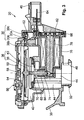
- FIG 2 shows a first embodiment of the IPMA 20 mounted on the charcoal canister 18.
- the IPMA 20 includes a housing 30 that can be mounted to the body of the charcoal canister 18 by a "bayonet" style attachment 32.
- a seal 34 is interposed between the charcoal canister 18 and the IPMA 20.
- This attachment 32 in combination with a snap finger 33, allows the IPMA 20 to be readily serviced in the field.
- different styles of attachments between the IPMA 20 and the body 18 can be substituted for the illustrated bayonet attachment 32, e.g., a threaded attachment, an interlocking telescopic attachment, etc.
- the body 18 and the housing 30 can be integrally formed from a common homogenous material, can be permanently bonded together (e.g., using an adhesive), or the body 18 and the housing 30 can be interconnected via an intermediate member such as a pipe or a flexible hose.
- Signaling 22 occurs when vacuum at the first predetermined pressure level is present in the charcoal canister 18.
- a pressure operable device 36 separates an interior chamber in the housing 30.
- the pressure operable device 36 which includes a diaphragm 38 that is operatively interconnected to a valve 40, separates the interior chamber of the housing 30 into an upper portion 42 and a lower portion 44.
- the upper portion 42 is in fluid communication with the ambient atmospheric pressure through a first port 46.
- the lower portion 44 is in fluid communication with a second port 48 between housing 30 the charcoal canister 18.
- the lower portion 44 is also in fluid communicating with a separate portion 44a via first and second signal passageways 50,52. Orienting the opening of the first signal passageway toward the charcoal canister 18 yields unexpected advantages in providing fluid communication between the portions 44,44a.
- Sealing between the housing pieces 30a,30b for the second signal passageway 52 can be provided by a protrusion 38a of the diaphragm 38 that is penetrated by the second signal passageway 52.
- a branch 52a provides fluid communication, over the seal bead of the diaphragm 38, with the separate portion 44a.
- a rubber plug 50a is installed after the housing portion 30a is molded. The force created as a result of vacuum in the separate portion 44a causes the diaphragm 38 to be displaced toward the housing part 30b. This displacement is opposed by a resilient element 54, e.g., a leaf spring.
- Pressure relieving 24 occurs as vacuum in the portions 44,44a increases, i.e., the pressure decreases below the calibration level for actuating the switch 58.
- Vacuum in the charcoal canister 18 and the lower portion 44 will continually act on the valve 40 inasmuch as the upper portion 42 is always at or near the ambient atmospheric pressure A.
- this vacuum will overcome the opposing force of a second resilient element 68 and displace the valve 40 away from a lip seal 70.
- the lip seal 70 will be described in greater detail below with reference to Figures 4 and 5.
- This displacement will open the valve 40 from its closed configuration, thus allowing ambient air to be drawn through the upper portion 42 into the lower the portion 44. That is to say, in an open configuration of the valve 40, the first and second ports 46,48 are in fluid communication. In this way, vacuum in the fuel system 10 can be regulated.
- Controllably connecting 28 to similarly displace the valve 40 from its closed configuration to its open configuration can be provided by a solenoid 72.
- the second resilient element 68 displaces the valve 40 to its closed configuration.
- a ferrous armature 74 which can be fixed to the valve 40, can have a tapered tip that creates higher flux densities and therefore higher pull-in forces.
- a coil 76 surrounds a solid ferrous core 78 that is isolated from the charcoal canister 18 by an O-ring 80. The flux path is completed by a ferrous strap 82 that serves to focus the flux back towards the armature 74. When the coil 76 is energized, the resultant flux pulls the valve 40 toward the core 78.
- Relieving pressure 26 is provided when there is a positive pressure in the lower portion 44, e.g., when the tank 12 is being refueled.
- the valve 40 is displaced to its open configuration to provide a very low restriction path for escaping air from the tank 12.
- the first and second signal passageways 50,52 communicate this positive pressure to the separate portion 44a.
- this positive pressure displaces the diaphragm 38 downward toward the valve 40.
- a diaphragm pin 39 transfers the displacement of the diaphragm 38 to the valve 40, thereby displacing the valve 40 to its open configuration with respect to the lip seal 70.
- pressure in the charcoal canister 18 due to refueling is allowed to escape through the lower portion 44, past the lip seal 70, through the upper portion 42, and through the second port 46.
- Relieving pressure 26 is also useful for regulating the pressure in fuel tank 12 during any situation in which the engine is turned off. By limiting the amount of positive pressure in the fuel tank 12, the cool-down vacuum effect will take place sooner.
- Figure 3 shows a second embodiment of the present invention that is substantially similar to the first embodiment shown in Figure 2, except that the first and second signal passageways 50,52 have been eliminated, and the intermediate lead frame 62 penetrates a protrusion 38b of the diaphragm 38, similar to the penetration of protrusion 38a by the second signal passageway 52, as shown in Figure 2.
- the signal from the lower portion 44 is communicated to the separate portion 44a via a path that extends through spaces between the solenoid 72 and the housing 30, through spaces between the intermediate lead frame 62 and the housing 30, and through the penetration in the protrusion 38b.
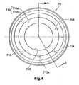
- the lip seal 70 i.e., a poppet valve seal
- the lip seal 70 can be an annular body surrounding an axis X and having a first sealing surface 702 and a second sealing surface 704.
- the first sealing surface 702 is fixed to the housing 30 and surrounds the aperture through which fluid flows between the first and second ports 46,48.
- the second sealing surface 704 generally confronts the valve 40, e.g., a poppet valve.
- annular lip 706 projects from the second sealing surface 704 and is resiliently deformed by the poppet valve 40 at its closed position, i.e., when fluid flow between the ports 46,48 is prevented.
- the annular lip 706 projects obliquely toward the axis X in an open position of the valve 40, i.e., when fluid flow between the ports 46,48 is permitted.
- the annular lip 706 can be in the shape of a hollow frustum such that an annular tip 708 surrounds a minimum axial cross-section with respect to the axis X.
- the wall thickness of the hollow frustum is less than 1 millimeter, and most preferably approximately 0.3 millimeters.
- the tip 708 of the annular lip 706 scrapes off any debris that may have accumulated on a sealing surface of the poppet valve 40.
- the poppet valve 40 resiliently deforms the annular lip 706 such that the tip 708 contracts radially toward the axis X, thereby scraping off any debris.
- the seal 70 can include a relatively resilient portion 710 and a relatively rigid portion 712 reinforcing the relatively resilient portion 710.
- the resilient portion 710 can be rubber, flurosilicone, or another elastomer
- the rigid portion 712 can be nylon.
- the resilient portion 710 can be molded onto the rigid portion 712, which can also include at least one channel 714 (eight are shown in Figure 4) to connect radially Inner portions 710a and radially outer portions 710b of the resilient portion 710 during molding.
- the rigid portion 712 can include a seat 712a matingly engaging the housing 30.
Landscapes
- Engineering & Computer Science (AREA)
- General Engineering & Computer Science (AREA)
- Mechanical Engineering (AREA)
- Chemical & Material Sciences (AREA)
- Combustion & Propulsion (AREA)
- Details Of Valves (AREA)
- Cooling, Air Intake And Gas Exhaust, And Fuel Tank Arrangements In Propulsion Units (AREA)
- Lift Valve (AREA)
- Supplying Secondary Fuel Or The Like To Fuel, Air Or Fuel-Air Mixtures (AREA)
Description
- This application claims the benefit of the earlier filing date of U.S. Provisional Application No. 60/166,404, filed 19 November 1999, which is incorporated by reference herein in its entirety.
- The present invention relates to a poppet valve seal for an integrated pressure management system that manages pressure and detects leaks in a fuel system. The present invention also relates to a poppet valve seal for an integrated pressure management system that performs a leak diagnostic for the headspace in a fuel tank, a canister that collects volatile fuel vapours from the headspace, a purge valve, and all associated hoses.
- In a conventional pressure management system for a vehicle, fuel vapour that escapes from a fuel tank is stored in a canister. If there is a leak in the fuel tank, canister or any other component of the vapour handling system, some fuel vapour could exit through the leak to escape into the atmosphere instead of being stored in the canister. Thus, it is desirable to detect leaks.
- In such conventional pressure management systems, excess fuel vapour accumulates immediately after engine shutdown, thereby creating a positive pressure in the fuel vapour management system. Thus, it is desirable to vent, or "blow-off", through the canister, this excess fuel vapour and to facilitate vacuum generation in the fuel vapour management system. Similarly, it is desirable to relieve positive pressure during tank refuelling by allowing air to exit the tank at high flow rates. This is commonly referred to as onboard refuelling vapour recovery (ORVR). Patent document FR 2385016 describes a seal for a poppet valve.
- Patent document US-1 671 140 A, which represents the closest prior art, describes a seal for a valve. The seal has an annular body with an annular lip contacting the valve surface during the closing action.
- The invention comprises a seal for a poppet valve, the poppet valve being movable between an open position permitting fluid flow through an aperture in a housing and a closed position preventing fluid flow through the aperture, the seal comprising: an annular body surrounding an axis and having first and second sealing surfaces, the first sealing surface being adapted to be fixed to the housing and surround the aperture, and the second sealing surface adapted to confront the poppet valve; an annular lip projecting from the second sealing surface and adapted to be resiliently deformed by the poppet valve at the closed position, the annular lip projecting obliquely toward the axis in the open position, characterised wherein the annular body includes a relatively resilient portion and a relatively rigid portion reinforcing the relatively resilient portion.
- The accompanying drawings, which are incorporated herein and constitute part of this specification, illustrate the present invention, and, together with the general description given above and the detailed description given below, serve to explain features of the invention. Like reference numerals are used to identify similar features.
- Figure 1 is a schematic illustration showing the operation of an integrated pressure management system.
- Figure 2 is a cross-sectional view of a first embodiment of an integrated pressure management system.
- Figure 3 is a cross-sectional view of a second embodiment of an integrated pressure management system.
- Figure 4 is a bottom view of a poppet valve seal according to the present invention.
- Figure 5 is a cross-section view taken along line V-V in Figure 4.
- Referring to Figure 1, a
fuel system 10, e.g., for an engine (not shown), includes afuel tank 12, avacuum source 14 such as an intake manifold of the engine, apurge valve 16, acharcoal canister 18, and an integrated pressure management system (IPMA) 20. - The IPMA 20 performs a plurality of functions including signaling 22 that a first predetermined pressure (vacuum) level exists, relieving
pressure 24 at a value below the first predetermined pressure level, relievingpressure 26 above a second pressure level, and controllably connecting 28 thecharcoal canister 18 to the ambient atmospheric pressure A. - In the course of cooling that is experienced by the
fuel system 10, e.g., after the engine is turned off, a vacuum is created in thetank 12 andcharcoal canister 18. The existence of a vacuum at the first predetermined pressure level indicates that the integrity of thefuel system 10 is satisfactory. Thus,signaling 22 is used for indicating the integrity of thefuel system 10, i.e., that there are no leaks. Subsequently relievingpressure 24 at a pressure level below the first predetermined pressure level protects the integrity of thefuel tank 12, i.e., prevents it from collapsing due to vacuum in thefuel system 10. Relievingpressure 24 also prevents "dirty" air from being drawn into thetank 12. - Immediately after the engine is turned off, relieving
pressure 26 allows excess pressure due to fuel vaporization to blow off, thereby facilitating the desired vacuum generation that occurs during cooling. During blow off, air within thefuel system 10 is released while fuel molecules are retained. Similarly, in the course of refueling thefuel tank 12, relievingpressure 26 allows air to exit thefuel tank 12 at high flow. - While the engine is turned on, controllably connecting 28 the
canister 18 to the ambient air A allows confirmation of the purge flow and allows confirmation of the signaling 22 performance. While the engine is turned off, controllably connecting 28 allows a computer for the engine to monitor the vacuum generated during cooling. - Figure 2, shows a first embodiment of the IPMA 20 mounted on the
charcoal canister 18. The IPMA 20 includes ahousing 30 that can be mounted to the body of thecharcoal canister 18 by a "bayonet"style attachment 32. Aseal 34 is interposed between thecharcoal canister 18 and the IPMA 20. Thisattachment 32, in combination with asnap finger 33, allows the IPMA 20 to be readily serviced in the field. Of course, different styles of attachments between the IPMA 20 and thebody 18 can be substituted for the illustratedbayonet attachment 32, e.g., a threaded attachment, an interlocking telescopic attachment, etc. Alternatively, thebody 18 and thehousing 30 can be integrally formed from a common homogenous material, can be permanently bonded together (e.g., using an adhesive), or thebody 18 and thehousing 30 can be interconnected via an intermediate member such as a pipe or a flexible hose. - The
housing 30 can be an assembly of amain housing piece 30a and housing piece covers 30b and 30c. Although two housing piece covers 30b,30c have been illustrated, it is desirable to minimize the number of housing pieces to reduce the number of potential leak points, i.e., between housing pieces, which must be sealed. Minimizing the number of housing piece covers depends largely on the fluid flow path configuration through themain housing piece 30a and the manufacturing efficiency of incorporating the necessary components of the IPMA 20 via the ports of the flow path. Additional features of thehousing 30 and the incorporation of components therein will be further described below. -
Signaling 22 occurs when vacuum at the first predetermined pressure level is present in thecharcoal canister 18. A pressureoperable device 36 separates an interior chamber in thehousing 30. The pressureoperable device 36, which includes adiaphragm 38 that is operatively interconnected to avalve 40, separates the interior chamber of thehousing 30 into anupper portion 42 and alower portion 44. Theupper portion 42 is in fluid communication with the ambient atmospheric pressure through afirst port 46. Thelower portion 44 is in fluid communication with asecond port 48 betweenhousing 30 thecharcoal canister 18. Thelower portion 44 is also in fluid communicating with aseparate portion 44a via first andsecond signal passageways charcoal canister 18 yields unexpected advantages in providing fluid communication between theportions housing pieces second signal passageway 52 can be provided by aprotrusion 38a of thediaphragm 38 that is penetrated by thesecond signal passageway 52. Abranch 52a provides fluid communication, over the seal bead of thediaphragm 38, with theseparate portion 44a. Arubber plug 50a is installed after thehousing portion 30a is molded. The force created as a result of vacuum in theseparate portion 44a causes thediaphragm 38 to be displaced toward thehousing part 30b. This displacement is opposed by aresilient element 54, e.g., a leaf spring. The bias of theresilient element 54 can be adjusted by acalibrating screw 56 such that a desired level of vacuum, e.g., one inch of water, will depress aswitch 58 that can be mounted on a printedcircuit board 60. In turn, the printed circuit board is electrically connected via anintermediate lead frame 62 to anoutlet terminal 64 supported by thehousing part 30c. An O-ring 66 seals thehousing part 30c with respect to thehousing part 30a. As vacuum is released, i.e., the pressure in theportions resilient element 54 pushes thediaphragm 38 away from theswitch 58, whereby theswitch 58 resets. - Pressure relieving 24 occurs as vacuum in the
portions switch 58. Vacuum in thecharcoal canister 18 and thelower portion 44 will continually act on thevalve 40 inasmuch as theupper portion 42 is always at or near the ambient atmospheric pressure A. At some value of vacuum below the first predetermined level, e.g., six inches of water, this vacuum will overcome the opposing force of a secondresilient element 68 and displace thevalve 40 away from alip seal 70. Thelip seal 70 will be described in greater detail below with reference to Figures 4 and 5. This displacement will open thevalve 40 from its closed configuration, thus allowing ambient air to be drawn through theupper portion 42 into the lower theportion 44. That is to say, in an open configuration of thevalve 40, the first andsecond ports fuel system 10 can be regulated. - Controllably connecting 28 to similarly displace the
valve 40 from its closed configuration to its open configuration can be provided by asolenoid 72. At rest, the secondresilient element 68 displaces thevalve 40 to its closed configuration. Aferrous armature 74, which can be fixed to thevalve 40, can have a tapered tip that creates higher flux densities and therefore higher pull-in forces. Acoil 76 surrounds a solidferrous core 78 that is isolated from thecharcoal canister 18 by an O-ring 80. The flux path is completed by aferrous strap 82 that serves to focus the flux back towards thearmature 74. When thecoil 76 is energized, the resultant flux pulls thevalve 40 toward thecore 78. Thearmature 74 can be prevented from touching thecore 78 by atube 84 that sits inside the secondresilient element 68, thereby preventing magnetic lock-up. Since very little electrical power is required for thesolenoid 72 to maintain thevalve 40 in its open configuration, the power can be reduced to as little as 10% of the original power by pulse-width modulation. When electrical power is removed from thecoil 76, the secondresilient element 68 pushes thearmature 74 and thevalve 40 to the normally closed configuration of thevalve 40. - Relieving
pressure 26 is provided when there is a positive pressure in thelower portion 44, e.g., when thetank 12 is being refueled. Specifically, thevalve 40 is displaced to its open configuration to provide a very low restriction path for escaping air from thetank 12. When thecharcoal canister 18, and hence thelower portions 44, experience positive pressure above ambient atmospheric pressure, the first andsecond signal passageways separate portion 44a. In turn, this positive pressure displaces thediaphragm 38 downward toward thevalve 40. Adiaphragm pin 39 transfers the displacement of thediaphragm 38 to thevalve 40, thereby displacing thevalve 40 to its open configuration with respect to thelip seal 70. Thus, pressure in thecharcoal canister 18 due to refueling is allowed to escape through thelower portion 44, past thelip seal 70, through theupper portion 42, and through thesecond port 46. - Relieving
pressure 26 is also useful for regulating the pressure infuel tank 12 during any situation in which the engine is turned off. By limiting the amount of positive pressure in thefuel tank 12, the cool-down vacuum effect will take place sooner. - Figure 3 shows a second embodiment of the present invention that is substantially similar to the first embodiment shown in Figure 2, except that the first and
second signal passageways intermediate lead frame 62 penetrates aprotrusion 38b of thediaphragm 38, similar to the penetration ofprotrusion 38a by thesecond signal passageway 52, as shown in Figure 2. The signal from thelower portion 44 is communicated to theseparate portion 44a via a path that extends through spaces between thesolenoid 72 and thehousing 30, through spaces between theintermediate lead frame 62 and thehousing 30, and through the penetration in theprotrusion 38b. - Referring to Figures 4 and 5, the
lip seal 70, i.e., a poppet valve seal, can be an annular body surrounding an axis X and having afirst sealing surface 702 and asecond sealing surface 704. Thefirst sealing surface 702 is fixed to thehousing 30 and surrounds the aperture through which fluid flows between the first andsecond ports second sealing surface 704 generally confronts thevalve 40, e.g., a poppet valve. - An
annular lip 706 projects from thesecond sealing surface 704 and is resiliently deformed by thepoppet valve 40 at its closed position, i.e., when fluid flow between theports annular lip 706 projects obliquely toward the axis X in an open position of thevalve 40, i.e., when fluid flow between theports annular lip 706 can be in the shape of a hollow frustum such that anannular tip 708 surrounds a minimum axial cross-section with respect to the axis X. According to a preferred embodiment, the wall thickness of the hollow frustum is less than 1 millimeter, and most preferably approximately 0.3 millimeters. - According to the present invention, as the
poppet valve 40 moves toward its closed position, thetip 708 of theannular lip 706 scrapes off any debris that may have accumulated on a sealing surface of thepoppet valve 40. In particular, thepoppet valve 40 resiliently deforms theannular lip 706 such that thetip 708 contracts radially toward the axis X, thereby scraping off any debris. - The
seal 70 can include a relativelyresilient portion 710 and a relativelyrigid portion 712 reinforcing the relativelyresilient portion 710. According to a preferred embodiment, theresilient portion 710 can be rubber, flurosilicone, or another elastomer, and therigid portion 712 can be nylon. Theresilient portion 710 can be molded onto therigid portion 712, which can also include at least one channel 714 (eight are shown in Figure 4) to connect radiallyInner portions 710a and radiallyouter portions 710b of theresilient portion 710 during molding. Therigid portion 712 can include aseat 712a matingly engaging thehousing 30.
Claims (8)
- A seal (70) for a poppet valve (40), the poppet valve being movable between an open position permitting fluid flow through an aperture in a housing and a closed position preventing fluid flow through the aperture, the seal comprising:an annular body surrounding an axis and having first and second sealing surfaces, the first sealing surface being adapted to be fixed to the housing and surround the aperture, and the second sealing surface adapted to confront the poppet valve;an annular lip (706) projecting from the second sealing surface and adapted to be resiliently deformed by the poppet valve at the closed position, the annular lip projecting obliquely toward the axis in the open position, characterised wherein the annular body includes a relatively resilient portion (710) and a relatively rigid portion (712) reinforcing the relatively resilient portion.
- The seal according to claim 1, wherein the annular lip (706) includes an annular tip (708) at a distal end with respect to the annular body, the annular tip being adapted for scrapingly engaging the poppet valve as the poppet valve moves toward the closed position.
- The seal according to claim 1, wherein the annular lip is a hollow frustum.
- The seal according to claim 3, wherein the hollow frustum has a wall thickness less than 1 millimeter.
- The seal according to claim 4, wherein the wall thickness is approximately 0.3 millimeters.
- The seal according to claim 2, wherein the relatively resilient portion is molded onto the relatively rigid portion.
- The seal according to claim 6, wherein the relatively rigid portion includes at least one channel extending radially with respect to the axis, the relatively resilient portion filling the at least one channel during molding.
- The seal according to claim 7, wherein the relatively rigid portion is adapted for engaging the housing.
Applications Claiming Priority (3)
| Application Number | Priority Date | Filing Date | Title |
|---|---|---|---|
| US543740 | 2000-04-05 | ||
| US09/543,740 US6623012B1 (en) | 1999-11-19 | 2000-04-05 | Poppet valve seat for an integrated pressure management apparatus |
| PCT/CA2001/000431 WO2001077549A2 (en) | 2000-04-05 | 2001-03-30 | Poppet valve seal |
Publications (2)
| Publication Number | Publication Date |
|---|---|
| EP1277004A2 EP1277004A2 (en) | 2003-01-22 |
| EP1277004B1 true EP1277004B1 (en) | 2006-10-04 |
Family
ID=24169381
Family Applications (1)
| Application Number | Title | Priority Date | Filing Date |
|---|---|---|---|
| EP01916818A Expired - Lifetime EP1277004B1 (en) | 2000-04-05 | 2001-03-30 | Poppet valve seal |
Country Status (6)
| Country | Link |
|---|---|
| US (1) | US6623012B1 (en) |
| EP (1) | EP1277004B1 (en) |
| JP (1) | JP2003530520A (en) |
| KR (1) | KR100770699B1 (en) |
| DE (1) | DE60123597T2 (en) |
| WO (1) | WO2001077549A2 (en) |
Families Citing this family (36)
| Publication number | Priority date | Publication date | Assignee | Title |
|---|---|---|---|---|
| DE69802954D1 (en) * | 1997-10-02 | 2002-01-24 | Siemens Canada Ltd | METHOD FOR TEMPERATURE CORRECTION AND SUBSYSTEM FOR AN ARRANGEMENT FOR EVAPORATION LEAK DETECTION OF VEHICLES |
| US20040140626A1 (en) * | 2003-01-16 | 2004-07-22 | Hall Matthew C. | Sealing device |
| US7121267B2 (en) * | 2003-03-07 | 2006-10-17 | Siemens Vdo Automotive, Inc. | Poppet for an integrated pressure management apparatus and fuel system and method of minimizing resonance |
| US20100108160A1 (en) * | 2005-09-06 | 2010-05-06 | Donald Gary Eichler | Feather gasket for an excess flow valve |
| SE529665C2 (en) * | 2005-09-09 | 2007-10-16 | Arca Systems Internat Ab | Valve and method of manufacture thereof |
| SE532137C2 (en) * | 2006-10-04 | 2009-10-27 | Tour & Andersson Ab | Valve with control function |
| US20080099082A1 (en) * | 2006-10-27 | 2008-05-01 | Honeywell International Inc. | Gas valve shutoff seal |
| US8905063B2 (en) | 2011-12-15 | 2014-12-09 | Honeywell International Inc. | Gas valve with fuel rate monitor |
| US8899264B2 (en) | 2011-12-15 | 2014-12-02 | Honeywell International Inc. | Gas valve with electronic proof of closure system |
| US9835265B2 (en) | 2011-12-15 | 2017-12-05 | Honeywell International Inc. | Valve with actuator diagnostics |
| US9846440B2 (en) | 2011-12-15 | 2017-12-19 | Honeywell International Inc. | Valve controller configured to estimate fuel comsumption |
| US8947242B2 (en) | 2011-12-15 | 2015-02-03 | Honeywell International Inc. | Gas valve with valve leakage test |
| US8839815B2 (en) | 2011-12-15 | 2014-09-23 | Honeywell International Inc. | Gas valve with electronic cycle counter |
| US9557059B2 (en) | 2011-12-15 | 2017-01-31 | Honeywell International Inc | Gas valve with communication link |
| US9074770B2 (en) | 2011-12-15 | 2015-07-07 | Honeywell International Inc. | Gas valve with electronic valve proving system |
| US9995486B2 (en) | 2011-12-15 | 2018-06-12 | Honeywell International Inc. | Gas valve with high/low gas pressure detection |
| US9851103B2 (en) | 2011-12-15 | 2017-12-26 | Honeywell International Inc. | Gas valve with overpressure diagnostics |
| DE102012012611A1 (en) | 2012-06-26 | 2014-01-02 | Audi Ag | Valve system for fuel system of motor vehicle, has stripping device arranged in seal lip, that is configured to strip-off contaminant in seal surface of valve element, when valve element is moved from open position into closed position |
| US9234661B2 (en) | 2012-09-15 | 2016-01-12 | Honeywell International Inc. | Burner control system |
| US10422531B2 (en) | 2012-09-15 | 2019-09-24 | Honeywell International Inc. | System and approach for controlling a combustion chamber |
| EP2868970B1 (en) | 2013-10-29 | 2020-04-22 | Honeywell Technologies Sarl | Regulating device |
| DE102013112586A1 (en) * | 2013-11-15 | 2015-05-21 | Dr. Ing. H.C. F. Porsche Aktiengesellschaft | Valve for a tank ventilation |
| US10024439B2 (en) | 2013-12-16 | 2018-07-17 | Honeywell International Inc. | Valve over-travel mechanism |
| US9841122B2 (en) | 2014-09-09 | 2017-12-12 | Honeywell International Inc. | Gas valve with electronic valve proving system |
| US9645584B2 (en) | 2014-09-17 | 2017-05-09 | Honeywell International Inc. | Gas valve with electronic health monitoring |
| US10503181B2 (en) | 2016-01-13 | 2019-12-10 | Honeywell International Inc. | Pressure regulator |
| US10230222B2 (en) | 2016-04-28 | 2019-03-12 | Novinium, Inc. | Injection electrical connector |
| US10564062B2 (en) | 2016-10-19 | 2020-02-18 | Honeywell International Inc. | Human-machine interface for gas valve |
| US10125874B2 (en) | 2016-10-24 | 2018-11-13 | Flowserve Management Company | Valves including multiple seats and related assemblies and methods |
| WO2018213313A1 (en) * | 2017-05-15 | 2018-11-22 | John Crane Uk Ltd. | Dry gas seal with electronically controlled carrier load |
| US11073281B2 (en) | 2017-12-29 | 2021-07-27 | Honeywell International Inc. | Closed-loop programming and control of a combustion appliance |
| US10697815B2 (en) | 2018-06-09 | 2020-06-30 | Honeywell International Inc. | System and methods for mitigating condensation in a sensor module |
| DE102021204982A1 (en) | 2021-05-18 | 2022-11-24 | Robert Bosch Gesellschaft mit beschränkter Haftung | Device for producing a fluidic connection and sealing it |
| US12158124B2 (en) | 2021-07-09 | 2024-12-03 | Stant Usa Corp. | Carbon canister with integrated fuel tank isolation valve |
| US12280656B2 (en) | 2021-10-18 | 2025-04-22 | Stant Usa Corp. | Carbon canister with direct connect fuel tank isolation valve |
| WO2023069416A1 (en) * | 2021-10-18 | 2023-04-27 | Stant Usa Corp. | Carbon canister with direct connect fuel tank isolation valve |
Family Cites Families (41)
| Publication number | Priority date | Publication date | Assignee | Title |
|---|---|---|---|---|
| US1671140A (en) * | 1926-01-25 | 1928-05-29 | Wylie G Wilson | Valve |
| US2157299A (en) * | 1935-11-05 | 1939-05-09 | Mercier Jean | Packing device, stuffing box, and the like |
| US2330881A (en) * | 1940-08-02 | 1943-10-05 | Jenkins Bros | Valve |
| US3110502A (en) * | 1957-11-29 | 1963-11-12 | Surelock Mfg Co Inc | Packing for hydraulic power units |
| US3129885A (en) * | 1962-04-30 | 1964-04-21 | American Radiator & Standard | Fluid line thermostat |
| US3190322A (en) * | 1962-10-03 | 1965-06-22 | J C Carter Company | Aircraft under-wing fueling nozzle and valve and sealing means therefor |
| US3640501A (en) * | 1969-10-02 | 1972-02-08 | George W Walton | Valve seal ring including metal retainer rings |
| GB1338143A (en) * | 1971-03-27 | 1973-11-21 | English Calico | Liquid control valves |
| US3861646A (en) * | 1972-10-27 | 1975-01-21 | Dresser Ind | Dual sealing element valve for oil well pumps |
| CH600223A5 (en) * | 1975-07-01 | 1978-06-15 | Vat Ag | |
| JPS52137287U (en) * | 1976-04-13 | 1977-10-18 | ||
| FR2385016A2 (en) * | 1977-02-22 | 1978-10-20 | Bouvier Ateliers | Valve with flexible seat - having undercut groove to form deformable lip to match profile of valve member on closure |
| JPS53122937A (en) * | 1977-04-01 | 1978-10-26 | Yamatake Honeywell Co Ltd | Sealed type rotary valve |
| US4240467A (en) * | 1979-01-15 | 1980-12-23 | Blatt L Douglas | Valve assembly |
| US4474208A (en) * | 1983-04-13 | 1984-10-02 | Baird Manufacturing Company | Safety valve |
| US4518329A (en) * | 1984-03-30 | 1985-05-21 | Weaver Joe T | Wear resistant pump valve |
| DE8613005U1 (en) * | 1986-05-13 | 1986-09-11 | Gebr. Hennig Gmbh, 8045 Ismaning | Stripping device for telescopic steel covers |
| US4766557A (en) | 1986-06-20 | 1988-08-23 | Westinghouse Electric Corp. | Apparatus for monitoring hydrogen gas leakage into the stator coil water cooling system of a hydrogen cooled electric generator |
| EP0317557B1 (en) | 1986-07-18 | 1991-02-27 | Werner Dr. Grabner | Process and device for measuring the vapour pressure of liquids |
| US4852054A (en) | 1986-11-20 | 1989-07-25 | Nde Technology, Inc. | Volumetric leak detection system for underground storage tanks and the like |
| US4766927A (en) * | 1987-01-29 | 1988-08-30 | Scott & Fetzer Company | Abrasive fluid control valve with plastic seat |
| DE3825076A1 (en) * | 1988-07-23 | 1990-01-25 | Bauer Fritz & Soehne Ohg | LENGTH ADJUSTABLE ADJUSTMENT |
| US4905505A (en) | 1989-03-03 | 1990-03-06 | Atlantic Richfield Company | Method and system for determining vapor pressure of liquid compositions |
| US4922957A (en) * | 1989-03-08 | 1990-05-08 | National-Oilwell | Valve with replaceable seal element |
| US4911407A (en) * | 1989-03-17 | 1990-03-27 | Paul Jr Herman L | Valve seat structure and assembly |
| US5273071A (en) * | 1992-03-05 | 1993-12-28 | Dover Corporation | Dry disconnect couplings |
| US5263685A (en) * | 1992-07-13 | 1993-11-23 | Orbit Valve Company | Valve seat |
| US5383437A (en) | 1992-12-23 | 1995-01-24 | Siemens Automotive Limited | Integrity confirmation of evaporative emission control system against leakage |
| DE4300629C1 (en) * | 1993-01-13 | 1994-03-24 | Draegerwerk Ag | Double valve with pressure compensation - has elastomer cone with lip forming one plug and other comprising pressure piece with elastomer covering |
| US5437257A (en) | 1994-02-28 | 1995-08-01 | General Motors Corporation | Evaporative emission control system with vent valve |
| US5623914A (en) | 1994-05-09 | 1997-04-29 | Nissan Motor Co., Ltd. | Air/fuel ratio control apparatus |
| DE4420960A1 (en) | 1994-06-16 | 1995-12-21 | Bosch Gmbh Robert | Pump device, in particular for a tank system of an internal combustion engine |
| US5474050A (en) | 1995-01-13 | 1995-12-12 | Siemens Electric Limited | Leak detection pump with integral vent seal |
| US5584271A (en) * | 1995-11-14 | 1996-12-17 | Freudenberg-Nok General Partnership | Valve stem seal |
| US6203022B1 (en) * | 1996-04-17 | 2001-03-20 | Lucas Industries Public Limited | Annular sealing element |
| JP3227389B2 (en) | 1996-07-26 | 2001-11-12 | 本田技研工業株式会社 | Evaporative fuel processor for internal combustion engines |
| JP3407566B2 (en) | 1996-11-05 | 2003-05-19 | 日産自動車株式会社 | Diagnosis device for evaporative fuel treatment equipment |
| DE19706264A1 (en) * | 1997-02-18 | 1998-08-20 | Press Controls Ruemlang Ag | Valve |
| US5893389A (en) * | 1997-08-08 | 1999-04-13 | Fmc Corporation | Metal seals for check valves |
| US6343505B1 (en) | 1998-03-27 | 2002-02-05 | Siemens Canada Limited | Automotive evaporative leak detection system |
| US6168168B1 (en) * | 1998-09-10 | 2001-01-02 | Albert W. Brown | Fuel nozzle |
-
2000
- 2000-04-05 US US09/543,740 patent/US6623012B1/en not_active Expired - Lifetime
-
2001
- 2001-03-30 EP EP01916818A patent/EP1277004B1/en not_active Expired - Lifetime
- 2001-03-30 WO PCT/CA2001/000431 patent/WO2001077549A2/en not_active Ceased
- 2001-03-30 KR KR1020027013324A patent/KR100770699B1/en not_active Expired - Fee Related
- 2001-03-30 DE DE60123597T patent/DE60123597T2/en not_active Expired - Lifetime
- 2001-03-30 JP JP2001574775A patent/JP2003530520A/en active Pending
Also Published As
| Publication number | Publication date |
|---|---|
| WO2001077549A3 (en) | 2002-02-07 |
| KR100770699B1 (en) | 2007-10-29 |
| JP2003530520A (en) | 2003-10-14 |
| DE60123597D1 (en) | 2006-11-16 |
| KR20030015224A (en) | 2003-02-20 |
| DE60123597T2 (en) | 2007-08-30 |
| US6623012B1 (en) | 2003-09-23 |
| WO2001077549A2 (en) | 2001-10-18 |
| EP1277004A2 (en) | 2003-01-22 |
Similar Documents
| Publication | Publication Date | Title |
|---|---|---|
| US6623012B1 (en) | Poppet valve seat for an integrated pressure management apparatus | |
| US6910500B2 (en) | Integrated pressure management system for a fuel system | |
| US6328021B1 (en) | Diaphragm for an integrated pressure management apparatus | |
| US6478045B1 (en) | Solenoid for an integrated pressure management apparatus | |
| US7040301B2 (en) | Fuel system with integrated pressure management | |
| EP1279082B1 (en) | Integrated pressure management apparatus having electronic control circuit | |
| US6983641B1 (en) | Method of managing pressure in a fuel system | |
| US6840232B2 (en) | Fluid flow through an integrated pressure management apparatus | |
| US6474313B1 (en) | Connection between an integrated pressure management apparatus and a vapor collection canister | |
| US6708552B2 (en) | Sensor arrangement for an integrated pressure management apparatus | |
| US6484555B1 (en) | Method of calibrating an integrated pressure management apparatus | |
| US6450153B1 (en) | Integrated pressure management apparatus providing an on-board diagnostic | |
| US6453942B1 (en) | Housing for integrated pressure management apparatus | |
| US6470908B1 (en) | Pressure operable device for an integrated pressure management apparatus | |
| US6505514B1 (en) | Sensor arrangement for an integrated pressure management apparatus | |
| US7121267B2 (en) | Poppet for an integrated pressure management apparatus and fuel system and method of minimizing resonance | |
| US6953027B2 (en) | Flow-through diaphragm for a fuel vapor pressure management apparatus | |
| WO2001086135A1 (en) | Method of managing pressure in a fuel system |
Legal Events
| Date | Code | Title | Description |
|---|---|---|---|
| PUAI | Public reference made under article 153(3) epc to a published international application that has entered the european phase |
Free format text: ORIGINAL CODE: 0009012 |
|
| 17P | Request for examination filed |
Effective date: 20021002 |
|
| AK | Designated contracting states |
Kind code of ref document: A2 Designated state(s): AT BE CH CY DE DK ES FI FR GB GR IE IT LI LU MC NL PT SE TR |
|
| REG | Reference to a national code |
Ref country code: SE Ref legal event code: TRGR |
|
| 17Q | First examination report despatched |
Effective date: 20040325 |
|
| RBV | Designated contracting states (corrected) |
Designated state(s): DE FR GB IT SE |
|
| GRAP | Despatch of communication of intention to grant a patent |
Free format text: ORIGINAL CODE: EPIDOSNIGR1 |
|
| GRAS | Grant fee paid |
Free format text: ORIGINAL CODE: EPIDOSNIGR3 |
|
| GRAA | (expected) grant |
Free format text: ORIGINAL CODE: 0009210 |
|
| AK | Designated contracting states |
Kind code of ref document: B1 Designated state(s): DE FR GB IT SE |
|
| PG25 | Lapsed in a contracting state [announced via postgrant information from national office to epo] |
Ref country code: IT Free format text: LAPSE BECAUSE OF FAILURE TO SUBMIT A TRANSLATION OF THE DESCRIPTION OR TO PAY THE FEE WITHIN THE PRESCRIBED TIME-LIMIT;WARNING: LAPSES OF ITALIAN PATENTS WITH EFFECTIVE DATE BEFORE 2007 MAY HAVE OCCURRED AT ANY TIME BEFORE 2007. THE CORRECT EFFECTIVE DATE MAY BE DIFFERENT FROM THE ONE RECORDED. Effective date: 20061004 |
|
| REG | Reference to a national code |
Ref country code: GB Ref legal event code: FG4D |
|
| REF | Corresponds to: |
Ref document number: 60123597 Country of ref document: DE Date of ref document: 20061116 Kind code of ref document: P |
|
| ET | Fr: translation filed | ||
| PLBE | No opposition filed within time limit |
Free format text: ORIGINAL CODE: 0009261 |
|
| STAA | Information on the status of an ep patent application or granted ep patent |
Free format text: STATUS: NO OPPOSITION FILED WITHIN TIME LIMIT |
|
| 26N | No opposition filed |
Effective date: 20070705 |
|
| PGFP | Annual fee paid to national office [announced via postgrant information from national office to epo] |
Ref country code: DE Payment date: 20140331 Year of fee payment: 14 Ref country code: SE Payment date: 20140319 Year of fee payment: 14 |
|
| PGFP | Annual fee paid to national office [announced via postgrant information from national office to epo] |
Ref country code: IT Payment date: 20140326 Year of fee payment: 14 Ref country code: FR Payment date: 20140319 Year of fee payment: 14 |
|
| PGFP | Annual fee paid to national office [announced via postgrant information from national office to epo] |
Ref country code: GB Payment date: 20140319 Year of fee payment: 14 |
|
| REG | Reference to a national code |
Ref country code: DE Ref legal event code: R119 Ref document number: 60123597 Country of ref document: DE |
|
| GBPC | Gb: european patent ceased through non-payment of renewal fee |
Effective date: 20150330 |
|
| PG25 | Lapsed in a contracting state [announced via postgrant information from national office to epo] |
Ref country code: SE Free format text: LAPSE BECAUSE OF NON-PAYMENT OF DUE FEES Effective date: 20150331 |
|
| REG | Reference to a national code |
Ref country code: SE Ref legal event code: EUG |
|
| PG25 | Lapsed in a contracting state [announced via postgrant information from national office to epo] |
Ref country code: IT Free format text: LAPSE BECAUSE OF NON-PAYMENT OF DUE FEES Effective date: 20150330 |
|
| REG | Reference to a national code |
Ref country code: FR Ref legal event code: ST Effective date: 20151130 |
|
| PG25 | Lapsed in a contracting state [announced via postgrant information from national office to epo] |
Ref country code: DE Free format text: LAPSE BECAUSE OF NON-PAYMENT OF DUE FEES Effective date: 20151001 Ref country code: GB Free format text: LAPSE BECAUSE OF NON-PAYMENT OF DUE FEES Effective date: 20150330 |
|
| PG25 | Lapsed in a contracting state [announced via postgrant information from national office to epo] |
Ref country code: FR Free format text: LAPSE BECAUSE OF NON-PAYMENT OF DUE FEES Effective date: 20150331 |