EP1276288A1 - Reference symbols for channel estimation with multicarrier transmission - Google Patents
Reference symbols for channel estimation with multicarrier transmission Download PDFInfo
- Publication number
- EP1276288A1 EP1276288A1 EP01116839A EP01116839A EP1276288A1 EP 1276288 A1 EP1276288 A1 EP 1276288A1 EP 01116839 A EP01116839 A EP 01116839A EP 01116839 A EP01116839 A EP 01116839A EP 1276288 A1 EP1276288 A1 EP 1276288A1
- Authority
- EP
- European Patent Office
- Prior art keywords
- ofdm
- preamble
- channel
- symbol stream
- frame
- Prior art date
- Legal status (The legal status is an assumption and is not a legal conclusion. Google has not performed a legal analysis and makes no representation as to the accuracy of the status listed.)
- Granted
Links
- 230000005540 biological transmission Effects 0.000 title claims description 89
- 238000000034 method Methods 0.000 claims abstract description 33
- 238000004891 communication Methods 0.000 claims abstract description 13
- 125000004122 cyclic group Chemical group 0.000 claims description 25
- 230000000694 effects Effects 0.000 claims description 7
- 230000002829 reductive effect Effects 0.000 claims description 5
- 238000003780 insertion Methods 0.000 abstract description 3
- 230000037431 insertion Effects 0.000 abstract description 3
- 230000006872 improvement Effects 0.000 abstract description 2
- 230000003190 augmentative effect Effects 0.000 abstract 2
- 230000003252 repetitive effect Effects 0.000 abstract 2
- 238000010276 construction Methods 0.000 abstract 1
- 230000006870 function Effects 0.000 description 17
- 238000005562 fading Methods 0.000 description 11
- 230000008901 benefit Effects 0.000 description 10
- 238000012546 transfer Methods 0.000 description 10
- 239000000654 additive Substances 0.000 description 9
- 230000000996 additive effect Effects 0.000 description 9
- 230000001419 dependent effect Effects 0.000 description 8
- 238000005070 sampling Methods 0.000 description 8
- 238000001914 filtration Methods 0.000 description 7
- 230000015556 catabolic process Effects 0.000 description 6
- 230000001427 coherent effect Effects 0.000 description 6
- 238000006731 degradation reaction Methods 0.000 description 6
- 238000001228 spectrum Methods 0.000 description 6
- 238000012937 correction Methods 0.000 description 5
- 230000005855 radiation Effects 0.000 description 5
- 230000006978 adaptation Effects 0.000 description 4
- 241000764238 Isis Species 0.000 description 3
- 230000000295 complement effect Effects 0.000 description 3
- 238000010586 diagram Methods 0.000 description 3
- 230000001771 impaired effect Effects 0.000 description 3
- 238000012545 processing Methods 0.000 description 3
- 230000004044 response Effects 0.000 description 3
- 230000002441 reversible effect Effects 0.000 description 3
- 230000002238 attenuated effect Effects 0.000 description 2
- 230000003139 buffering effect Effects 0.000 description 2
- 239000000969 carrier Substances 0.000 description 2
- 238000006243 chemical reaction Methods 0.000 description 2
- 230000007423 decrease Effects 0.000 description 2
- 230000007274 generation of a signal involved in cell-cell signaling Effects 0.000 description 2
- 238000013507 mapping Methods 0.000 description 2
- 230000000737 periodic effect Effects 0.000 description 2
- 230000010363 phase shift Effects 0.000 description 2
- 238000000926 separation method Methods 0.000 description 2
- 230000008054 signal transmission Effects 0.000 description 2
- 230000003595 spectral effect Effects 0.000 description 2
- 240000007594 Oryza sativa Species 0.000 description 1
- 235000007164 Oryza sativa Nutrition 0.000 description 1
- 230000003044 adaptive effect Effects 0.000 description 1
- 230000002411 adverse Effects 0.000 description 1
- 230000003321 amplification Effects 0.000 description 1
- 238000013459 approach Methods 0.000 description 1
- 239000000872 buffer Substances 0.000 description 1
- 230000003247 decreasing effect Effects 0.000 description 1
- 230000007812 deficiency Effects 0.000 description 1
- 230000006735 deficit Effects 0.000 description 1
- 238000013461 design Methods 0.000 description 1
- 238000001514 detection method Methods 0.000 description 1
- 238000005516 engineering process Methods 0.000 description 1
- 238000011156 evaluation Methods 0.000 description 1
- 230000036039 immunity Effects 0.000 description 1
- 238000005259 measurement Methods 0.000 description 1
- 238000010295 mobile communication Methods 0.000 description 1
- 238000012986 modification Methods 0.000 description 1
- 230000004048 modification Effects 0.000 description 1
- 238000010606 normalization Methods 0.000 description 1
- 238000003199 nucleic acid amplification method Methods 0.000 description 1
- 230000008569 process Effects 0.000 description 1
- 235000009566 rice Nutrition 0.000 description 1
- 239000004065 semiconductor Substances 0.000 description 1
- 230000035945 sensitivity Effects 0.000 description 1
- 238000005309 stochastic process Methods 0.000 description 1
- 230000001360 synchronised effect Effects 0.000 description 1
Images



Classifications
-
- H—ELECTRICITY
- H04—ELECTRIC COMMUNICATION TECHNIQUE
- H04L—TRANSMISSION OF DIGITAL INFORMATION, e.g. TELEGRAPHIC COMMUNICATION
- H04L27/00—Modulated-carrier systems
- H04L27/26—Systems using multi-frequency codes
- H04L27/2601—Multicarrier modulation systems
- H04L27/2602—Signal structure
- H04L27/261—Details of reference signals
- H04L27/2613—Structure of the reference signals
-
- H—ELECTRICITY
- H04—ELECTRIC COMMUNICATION TECHNIQUE
- H04L—TRANSMISSION OF DIGITAL INFORMATION, e.g. TELEGRAPHIC COMMUNICATION
- H04L25/00—Baseband systems
- H04L25/02—Details ; arrangements for supplying electrical power along data transmission lines
- H04L25/0202—Channel estimation
-
- H—ELECTRICITY
- H04—ELECTRIC COMMUNICATION TECHNIQUE
- H04L—TRANSMISSION OF DIGITAL INFORMATION, e.g. TELEGRAPHIC COMMUNICATION
- H04L27/00—Modulated-carrier systems
- H04L27/26—Systems using multi-frequency codes
- H04L27/2601—Multicarrier modulation systems
- H04L27/2614—Peak power aspects
- H04L27/262—Reduction thereof by selection of pilot symbols
-
- H—ELECTRICITY
- H04—ELECTRIC COMMUNICATION TECHNIQUE
- H04L—TRANSMISSION OF DIGITAL INFORMATION, e.g. TELEGRAPHIC COMMUNICATION
- H04L27/00—Modulated-carrier systems
- H04L27/26—Systems using multi-frequency codes
- H04L27/2601—Multicarrier modulation systems
- H04L27/2602—Signal structure
- H04L27/261—Details of reference signals
- H04L27/2613—Structure of the reference signals
- H04L27/26136—Pilot sequence conveying additional information
Definitions
- the present invention generally relates to the field of wireless communication systems with high-speed mobile access, especially to wireless communication systems using reference symbols to support channel tracking in high-speed wireless multi-carrier systems.
- a broadband radio channel as needed for the transmission of high data rates, is characterized by severe attenuation fades (frequency-selective fading) caused by the multipath propagation of the transmitted mobile radio signals.
- severe attenuation fades frequency-selective fading
- it exhibits a time-variant behavior due to the mobility of the receiver, which possibly requires a continuous adaptation of the transmission system to said behavior.
- OFDM Orthogonal Frequency Division Multiplexing
- W-ATM Wireless Asynchroncus Transfer Mode
- DMT Asymmetric Digital Subscriber Lines
- Multicarrier modulation is also considered for use in high-speed modems, but so far all ITU-T (formerly CCITT) standards refer to single-carrier systems.
- OFDM was initially standardized for the two high-speed digital radio transmission systems Digital Audio Broadcasting (DAB) and Digital Video Broadcasting Terrestrial transmission mode (DVB-T), which are used for transmitting digital radio and television signals. Both systems are real broadcast systems for transmitting data via broadband radio channels.
- DAB Digital Audio Broadcasting
- DVD-T Digital Video Broadcasting Terrestrial transmission mode
- Both systems are real broadcast systems for transmitting data via broadband radio channels.
- DAB was originally developed for mobile reception, it is able to transmit data rates of up to 1.7 MBit/s.
- DVB-T more than 20 MBit/s can be transmitted -, however, the system was originally developed for stationary reception. Aside from video signal transmission, today additional data services are planned for DVB-T.
- OFDM is a viable technology for high-speed data transmission over spectrally shaped noisy channels.
- a further field of application, for which the OFDM transmission system plays an increasing role, is the mobile access to wire-bound networks with the aid of a local radio network, whereby high data rates shall also be transmitted.
- the HIPERLAN/2 standard as well as an extension of the IEEE 802.11 standard for the 5 GHz area can be mentioned.
- the OFDM transmission system is applied.
- broadband single-carrier systems have been specified with the denotation Universal Mobile Telecommunications System (UMTS).
- UMTS Universal Mobile Telecommunications System
- a higher data rate would cause a very high expenditure during the channel equalization.
- OFDM could also offer a sensible alternative for real mobile applications, and thus represent an important step for the mobile Internet.
- ISI intersymbol interference
- the transmitted data is split into a number of parallel data streams, each one used to modulate a separate subcarrier.
- FDM Frequency Division Multiplex
- different signals are independently generated and parallel transmitted using different frequency bands.
- the channel spectrum is parsed into a large number of parallel subchannels which are, in the ideal case, independent and ideally frequency-nonselective.
- the spectral subcarrier separation in the receiver is achieved by means of steep bandpass filters, resulting in a considerable amount of realization complextity, especially if the number of the employed subcarriers is very high.
- OFDM is known to be an elegant solution for the severe ISI problem, as it avoids an equalization of the entire band.
- OFDM transmission systems manage the above-described situation by dividing up the broadband radio channel into many narrow-band subchannels. Instead of converting a single carrier with 10 7 second modulation symbol per second, for instance, 1,000 subcarriers modulated with only 10 4 modulation symbols per second can be transmitted. Considering a channel with a maximum delay ⁇ max of 10 ⁇ s, ISIs can thus easily be equalized or avoided.
- the main advantage of OFDM is that no high-order bandpass filters with steep slopes are needed, as each orthogonal subcarrier can use the entire spectrum. With the aid of orthogonal subcarriers an easy separation of the individual subcarriers in the receiver is achievable.
- the broadband radio channel is subdivided into a plurality of narrow-band subchannels (subcarriers) being independently modulated.
- the signals are generated together with the aid of a Discrete Fourier Transform (DFT), and their spectra overlap mutually.
- DFT Discrete Fourier Transform
- Each subchannel only covers a small part of the total available frequency band, and as a consequence channel equalization becomes much simpler than in a single-carrier system. Instead of severely distorting several adjacent symbols, burst errors caused by fading only slightly distort a plurality of symbols.
- the most important advantage of the OFDM transmission system arises in connection with frequency-selective channels.
- the radio channel can approximately be deemed as frequency-nonselective.
- the signal processing in the receiver can extremely be simplified, as the orthogonality of the OFDM subcarriers can be maintained during the whole transfer over the mobile radio channel.
- just one complex transmission coefficient has to be estimated for each subcarrier.
- the channel influence only consists in a multiplication with a complex transmission coefficient, aside from additive noise. Thereby, the object of a channel equalizer decreases to dividing each symbol by its respective transmission coefficient. In this way, a simple channel equalization is enabled, whereas possibly an equalization is not realizable if a single-carrier system with the same bandwidth is employed.
- the channel equalization can easily be performed.
- a coherent demodulation is enabled and, for instance, a Quadrature Amplitude Modulation (QAM) can be applied.
- QAM Quadrature Amplitude Modulation
- M-DPSK Differential Phase-Shift Keying
- the (adaptive) equalization for coherent demodulation is simplified to a frequency-domain equalization comprising one complex multiplier per subcarrier in an appropriately designed OFDM system.
- the multipath channel causes an attenuation and a phase rotation of each subcarrier amplitude.
- phase-shift keying PSK
- PSK phase-shift keying
- not even an amplitude equalization is needed; it is enough to correct the phase variation.
- differentially encoded modulation is used in the subcarriers, no channel estimation and correction is needed at all.
- a channel estimation When using coherent modulation in the subcarriers, a channel estimation must be performed in the OFDM receiver.
- the optimality of a two-dimensional Wiener filter to obtain estimates for the channel gains of a dispersive and time-variant channel is well-known in the state of the art. Thereby, the two dimensions need to be identified with the frequency-time grid spanned by the subsequent OFDM symbols in the frequency domain. Furthermore, so-called "pilot tones" are regularly multiplexed into the information-carrying OFDM symbols.
- CP cyclic prefix
- P preamble field
- OFDM transmission systems are degraded by all influences which destroy said mutual subcarrier orthogonality. Hence, it is sensitive to carrier frequency offsets, and therefore, synchronization within a small fraction of a subcarrier spacing is crucial. Additionally, the OFDM symbol start needs to be identified in the receiver. Further negative effects like the degradation in a frame-off-set or timing-jitter scenario and the influence of a non-synchronized sampling are analyzed in the relevant literature.
- An OFDM signal is an ensemble of many narrowband subchannels. Therefore, the transmit signal of OFDM exhibits a high dynamic range and a large crest factor. Intermodulation as well as out-of-band power (spurious tones) are generated. Nonlinear devices like the power amplifier of the transmitter must be able to cope with the high dynamic range of the transmit signal to keep the out-of-band radiation under a certain limit imposed by the employed spectrum masks according to the underlying standard. This leads to an inefficient amplification and a large power consumption. Due to said effects many bit errors still occur - even at a high mean signal-to-noise ratio. For this reason, an efficient channel coding is needed for transmission systems using OFDM.
- the energy received during the guard interval is wasted, as it is not used for the detection process of the receiver.
- the maximum channel impulse response duration is long in comparison with the modulation interval, the number of carriers must be high to keep the loss in power efficiency due to the guard interval in reasonable limits.
- An OFDM baseband signal s(t) consists of K equidistant subcarrier signals g k (t) (1 ⁇ k ⁇ K) having a subchannel spacing of ⁇ f.
- the system bandwidth B sys is divided up into K equidistant subchannels.
- a so-called "guard interval" with the length T G is prefixed to the signal g k (t) representing a periodic repetition of said signal g k (t).
- Each of the K subcarrier signals g k (t) can be modulated with a complex modulation symbol S n,k , wherein the index n refers to the modulation interval and the index k indicates the subcarrier signal g k (t) in the neighboring OFDM block.
- the OFDM baseband signal s(t) is sampled with a sampling rate of K ⁇ f ( ⁇ B)
- a time-discrete signal corresponding to the Inverse Discrete Fourier Transform (IDFT) of S n,k the n-th transmitted modulation symbol of the k-th subcarrier g k (t) arises for the n-th OFDM block.
- the time-discrete transmission signal can be generated from the sequence of the modulation symbols of all K subcarrier signals g k (t) by an IDFT which is realized as an Inverse Fast Fourier Transform (IFFT).
- IFFT Inverse Fast Fourier Transform
- the modulation symbols R n,k can be retrieved from the sampled receive signal in the receiver by means of a Fast Fourier transform (FFT).
- FFT Fast Fourier transform
- the transfer function H(f,t) of the channel can be regarded as quasi-stationary within the bandwidth ⁇ f of a subcarrier signal g k (t) and the duration T MC of a modulation symbol S n,k .
- said OFDM subchannels can be modelled by means of Rayleigh channels or, with existing line of sight (LOS) connection, by means of Rice channels. These models imply an ideal interleaving, i.e. the transmission coefficients are uncorrelated in the latter case.
- WSSUS Wide Sense Stationary Uncorrelated Scattering
- the transmission of signals by means of an OFDM transmission system comprises the following steps:
- pilot symbols which are possibly needed for the channel estimation and equalization must also be transmitted, dependent on the applied modulation technique. Obtained in this way, the digital baseband signal is then submitted to a D/A conversion, modulated to the carrier wave, amplified, and transmitted over the channel. In the receiver the complementary operations are applied in reverse order.
- the receiver In order to assign an information to the received modulation symbols R n,k , which are attenuated and distorted in their phase as well as impaired by additive noise, the receiver must know the complex transmission coefficients H n,k . Demodulation techniques with said peculiarity are designated as "coherent" in technical language. Since the receiver can not ascertain the precise transmission coefficients H n,k , though, a channel estimation must be carried out instead which provides the estimated values H and n,k for the transmission coefficients H n,k . After that, the receiver can make a decision with the aid of the following evaluation:
- the receiver is able to retrieve the transmitted modulation symbol S n,k by means of simple threshold value decisions from .
- the receiver measures the transmission coefficients at that times and at those frequencies at which said pilot patterns were transmitted.
- an interpolation which can preferably be realized as a filtering, yields the remaining transmission coefficients.
- the transmission capacity of the system decreases due to the transmission of pilot symbols if said channel estimation is applied.
- said pilot symbols are impaired by additive noise just as the remaining modulation symbols, so that the transfer function can not exactly be determined. The more pilot symbols are available, the more precisely the transfer function can be determined, however, the more data transmission capacity is wasted.
- the distances of the pilot symbols should be n t modulation intervals and n f subcarrier signals at the most, with n t and n f fulfilling the inequations n t ⁇ 1 / (2f D,max ⁇ T MC ) or n f ⁇ 1 / (2 ⁇ max ⁇ f) respectively, in which the herein used variables are defined as follows:
- the interpolation can be realized by a two-dimensional filtering or by consecutive filtering in frequency and time direction.
- T coh ⁇ 1 2 ⁇ f D ⁇ arc cos(c), wherein c is defined as the considered coherence level, and f D is the Doppler shift.
- c is defined as the considered coherence level
- f D is the Doppler shift.
- the square brackets in the formula above round the value of its argument to the one higher integer value.
- a single-shot channel estimation (based on a single multi-carrier pilot sequence) at the beginning of each data burst is not sufficient, as the radio channel exhibits a time-variant behavior due to the mobility of the users. If the frequency range of the carrier frequency is shifted from the 6-GHz band towards higher carrier frequencies, the degradation becomes worse.
- the physical layer (PHY)
- OFDM transmission is applied to the physical layer (PHY).
- PHY physical layer
- the main functions of the PHY layer are briefly described.
- the Data Link Control layer (DLC)
- the object of the Data Link Control layer is to share the common used physical medium, the radio channel, among the mobile stations (MS) in a fair and efficient way.
- a further object of said layer is to secure the transmission against errors occuring due to the transmission over the radio channel for each single connection.
- the DLC layer is divided up into two sublayers called Medium Access Control (MAC) and Logical Link Control (LLC).
- MAC Medium Access Control
- LLC Logical Link Control
- the MAC sublayer the physical channel is subdivided into time slots applying a TDMA technique.
- the MAC sublayer is responsible for assigning transmission capacity to the respective mobile stations, dependent on their specific requirements.
- the LLC sublayer provides an error correction by means of an Automatic Repeat Request (ARQ) protocol.
- ARQ Automatic Repeat Request
- the MAC sublayer divides the physical channel into frames of constant lengths.
- a frame length of 2 ms is prescribed.
- an OFDM symbol duration of 4 ⁇ s is given, this corresponds to 500 OFDM symbols per frame.
- the frame is divided into transmission stages with different functions as can be seen in the following figure:
- the access to the common used physical channel is coordinated by a central instance, the Access Point (AP) or the Central Controller (CC), respectively. It dynamically assignes transmission capacity in the form of time slots. Therefore, the AP needs information about the number and the service class of the data packets in the mobile terminals (MT) waiting for being transmitted.
- AP Access Point
- CC Central Controller
- transport channels are offered by the physical layer (PHY).
- PHY physical layer
- BCH Broadcast Channel
- FCH Frame Channel
- the parameters of the transport channels according to the ETSI-BRAN standard can be taken from the following table: Physical Channel Direction of the transmission Length [Byte] Access Feedback Channel (ACH) Downlink 9 Broadcast Channel (BCH) Downlink 15 Frame Channel (FCH) Downlink n ⁇ 27 Long Transport Channel (LCH) Down-/Uplink 54 Short Transport Channel (SCH) Down-/Uplink 9 Random Access Channel (RCH) Uplink 9
- BCH Broadcast Channel
- FCH Frame Channel
- LCH Long Transport Channel
- SCH Short Transport Channel
- RCH Random Access Channel
- the HIPERLAN/2 standard defines two PHY bursts, as described above, each for the downlink and for the uplink, respectively, and an optional Direct Link burst which shall not be considered here.
- PDU Protocol Data Unit
- DLC Data Link Control layer
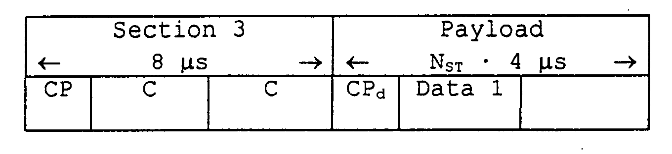
- Section 1 and 2 of the broadcast burst are designed for the identification of the MAC frame start, whereas section 3 is designed to be used for a channel estimation.
- Section 2 of the uplink burst is also designed to enable a successful automatic gain control (AGC) adjustment for all channels. Further details can be taken from the HIPERLAN/2 specification.
- the data part, called payload contains the OFDM symbols being transmitted on fixed subcarriers. Thereby, four pilot symbols are multiplexed into each payload OFDM symbol. Typically, these pilot symbols are used for frequency tracking purposes. Since they are allocated to fixed subcarriers and usually do not fulfil the sampling theorem in frequency direction, they can not be used for channel tracking.
- sytems data packets are transmitted comprising a so-called preamble (which consists of OFDM symbols) followed by data OFDM symbols.
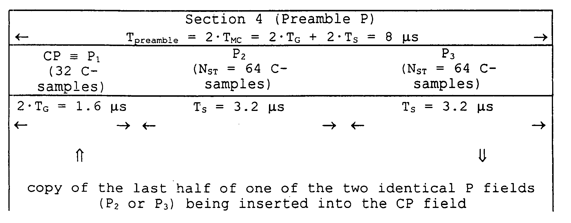
- a QPSK modulation with a code rate of 3/4 is applied, the length of the total burst (comprising said preamble and said data) can, for instance, vary between 16 ⁇ s (preamble length: 8 ⁇ s, data length: 8 ⁇ s, if only one SCH is applied) and 1,928 ⁇ s (preamble length: 8 ⁇ s, data length: 1,920 ⁇ s, if 80 SCHs are applied).
- said extension field (CP) is composed of a cyclic repetition of said OFDM symbols (P 2 , P 3 ) comprising a copy of the last 32 samples of one of the two OFDM symbols (P 2 or P 3 ). It is thus double in length compared to the cyclic prefix (CP d ) of normal data symbols.
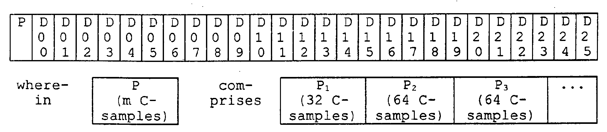
- the entire burst is formed by concatenating the above-described preamble (P ⁇ P 1 ) with the data payload comprising the data OFDM symbols, and possibly with other preambles (P 2 , P 3 , ...) as depicted below:
- the scrambling of pilot patterns of any kind is applied to randomize the deterministic behavior of predefined pilots in order to minimize deterministic spectral peaks.
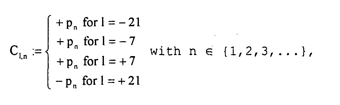
- the reference signal transmitted over the subcarriers referring to the continuous pilot pattern C l,n with the parameters l and n is defined as follows: wherein p is a sequence used for randomizing the transmitted reference signal.
- Each sequence element is used for a single OFDM symbol.
- the scrambler defined in that way should be initialized at the beginning of each PDU train.
- the continuous pilot pattern C l,n is not used for a channel estimation with the purpose to equalize the channel, but e.g. for the purpose of a phase tracking.
- OFDM demodulation consists of three steps: 1. locating the starting point of an OFDM symbol, 2. separating all subcarriers by applying the Discrete Fourier Transform (DFT), and 3. mapping the received symbols into bits.
- DFT Discrete Fourier Transform
- each of the applied pilot pattern based channel estimation and/or channel tracking techniques is optimized to a specific purpose, and thus it contains certain limitations.
- HIPERLAN/2 no channel tracking is performed.
- the channel transfer function is estimated during the preamble part of the data burst, and remains fixed during the entire burst ("single-shot channel estimation") to support a coherent demodulation of the received signal. Any channel variations during the reception of the burst, for example caused by the mobility of the users, are not tracked. Therefore, a degradation of the data transmission for any time-variant channels must be expected. Additionally, as there is no update of said single-shot channel estimation, a poor quality channel estimation at the beginning reduces the reception quality of the whole burst.
- pilot pattern applied to the DVB-T standard is an optimized solution for time-variant channels. Nevertheless, a significant disadvantage of this pilot pattern is the complexity of its implementation, for example concerning the required processing power for the interpolation, and the buffers needed for storing multiple complete OFDM symbols.
- the implementation complexity is also a fundamental disadvantage of pilot patterns applied to the DFE standard, likewise concerning the required processing power.
- the DFE equalizer needs valid channel state information as well (as starting point), and thus a proper pilot pattern is required.
- Channel tracking can also be performed by applying a Decision Feedback Equalization (DFE).
- DFE Decision Feedback Equalization
- the usage of DFE is restricted to the lower level modulation schemes (e.g. BPSK and QPSK), whereas the channel tracking is unsatisfactory for other modulation schemes (e.g. 16QAM and 64QAM).
- the usage of a DFE implies a significant increase in the complexity of the applied receiver architecture.
- the underlying invention describes a low-complexity and low-effort solution for a pilot pattern of a pilot-assisted high-speed wireless multi-carrier system used for supporting mobile applications within envircnments being severely impaired by a time-varying multipath fading behavior of the mobile radio channel.
- the invention is specially optimized for extending conventional "single-shot" pilot pattern based channel estimation schemes to cope with said severe channel conditions, and can easily be realized. Additionally, the proposed scheme allows a continuous improvement of a single-shot channel estimation.
- the existing preamble (or parts of said preamble) is multiplexed into the OFDM symbol stream of a associated data burst to support channel tracking in the receiver.
- the already defined preamble is used, since it implies the advantage of an easy implementation without changing the existing channel estimation algorithm.
- the guard interval is inserted to suppress ISI caused by multipath distortion.
- Said guard interval is also called cyclic prefix (CP). It comprises a copy of the last part of the OFDM symbol which is placed in front of the transmitted symbol. This makes the transmitted symbol periodic, which plays a decisive role in correctly identifying frames to avoid ISI and ICI.
- the price one has to pay for this advantage is a loss of signal-to-noise ratio, as the cyclic prefix is subjected to the "noisy" channel just as the signal is concerned, and by occupying signal space less power is provided for the transmission of the signal frame.
- a filtering function is applied in order to reduce the out-of-band radiation.
- the signal is submitted to a D/A conversion to produce the analog baseband signal, upconverted to the radio frequency (RF), and finally transmitted.
- RF radio frequency
- the independent patent claim 1 and the dependent claims 2 to 9 refer to a mobile transmission system comprising at least one mobile transmitter and/or at least one mobile receiver for supporting wireless communication over a mobile radio channel by means of pilot-assisted wireless multi-carrier systems.
- said multi-carrier system comprises at least one antenna for receiving and transmitting modulated RF signals, respectively, means for performing an OFDM multi-carrier modulation and an OFDM multi-carrier demodulation, and means for performing a channel estimation, a channel equalization and/or a synchronization between said mobile transmitter and said mobile receiver on the basis of at least one pilot subcarrier pattern comprising one or more pilot pattern frames included in at least one data burst of the transmitted RF signal.
- the frame of a pilot pattern transmitted by means of a pilot subcarrier pattern comprises at least one preamble frame for performing a channel estimation and/or a synchronization of the mobile transmitter and the mobile receiver. It contains one cyclic prefix field and/or at least one preamble field for performing a channel estimation.
- the claimed mobile transmission system is characterized in that at least one field of said preamble frame is multiplexed into the OFDM symbol stream of the associated data burst in order to enable an improved channel estimation despite degradations caused by multipath fading, additive noise and the time variance of the mobile radio channel.
- independent patent claim 10 and the dependent claims 11 to 18 relate to a method for supporting wireless communication over a mobile radio channel by means of pilot-assisted wireless multi-carrier systems as described above.
- the independent patent claim 19 refers to a mobile telecommunications device, wherein a mobile transmitter and/or a mobile receiver is employed for supporting a method according to anyone of the claims 10 to 18.
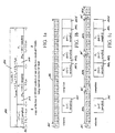
- the independent patent claim 20 and the dependent claims 21 to 27 relate to a data burst structure, wherein at least one preamble frame 100 followed by an OFDM symbol stream 106 is applied, having one cyclic prefix field 105a comprising reference symbols used for correctly identifying the beginning of a transmitted extended OFDM symbol stream 105 and 107a-d, and/or at least one preamble field 105b, 105c and/or 105d for performing a channel estimation.
- the OFDM symbol stream 106 is extended by multiplexing one preamble frame 105 after each N-th OFDM data symbol within the associated data burst, in which N advantageously may be defined 2 M , and M is a positive integer value.
- Figure 1b shows the unextended OFDM symbol stream 106; the extended OFDM symbol stream 107 comprising data symbols 107a-d and multiplexed reference symbols 105 can be taken from figure 1c.
- the multiplexing of the modified preamble (P') field 206 remains the same as described above for the unchanged preamble (P) field 201, which is again depicted in figure 2a.
- Figure 2c shows the unextended OFDM symbol stream 211; the extended OFDM symbol stream 212 comprising data symbols 212a-d and multiplexed reference symbols 209 and 210, respectively, can be seen in figure 2d.
- the main object of an applied pilot scrambling sequence is to randomize (to "whiten") the transmitted signal.
- it is proposed to maintain said scrambling even during the transmission of the additional reference symbol. That means that from the pilot scrambler point of view the multiplexing of additional reference symbols is transparent.
- the additional reference symbols it is proposed to multiply the complete additional reference symbol (and not only the carriers at the four pilot positions) with the actual scrambling value SC n ⁇ ⁇ -1, +1 ⁇ . Furthermore, as an additional advantage, said multiplication serves to randomize the spectrum of the signal to be transmitted.
- the multiplication of the additional reference symbol can either be performed in the time domain by multiplying the complex samples with either '+1' or '-1', or in the frequency (subcarrier) domain by multiplying the complex subcarrier information of the additional reference symbol information with either '+1' or '-1' as shown in the figures 3c and 3d, respectively.
- Figure 3a shows again the structure of the unchanged preamble (P) field 301, whereas figure 3b exhibits the structure of the modified preamble (P') field 306.
- the other components 309-312d depicted in the figures 3b and 3c are identical with the above-described components 209-212d depicted in the figures 2b and 2c.
- channel estimation is needed for each separate transmitting antenna. This is applicable to schemes like Space-Time Block Coding (STC), which uses multiple transmitting antennas.
- STC Space-Time Block Coding
- the symbol 'P' refers to the sequence of channel estimation information (P 1 ...P ⁇ ...P m ) obtained from each of the m antennas.
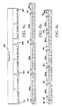
- An other multiplexing option is, for instance, alternatively multiplexing channel estimation symbols from one or the other transmitting antenna into the OFDM symbol stream 407a-f as shown in figure 4c.
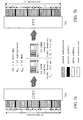
- channel estimates 507a-d are steadily exploited during the reception of the extended OFDM symbol stream comprising data symbols 508a-d and multiplexed reference symbols 501 and 505, respectively, by weighting previously obtained channel estimates 507a-d in order to reduce the effect of noise on the channel estimation.
- the employed weights are typically powers of a number within the range of 0 to 1.
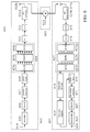
- Figure 6 refers to a block diagram for the employed mobile transmission system comprising one transmitter 601 and one receiver 602 for supporting wireless communication over a mobile radio channel by means of a pilot-assisted wireless multi-carrier system considering channel estimation and equalization.
- the input is a binary data stream 604.
- a scrambler 605 is used for randomizing the transmitted input data bits 604.
- the data is then transformed into a multilevel signal to be prepared for an OFDM modulation 609.
- the serial data stream is converted to parallel by means of the serial-parallel converter 609a, the data rate gets reduced by N, where N is the number of parallel subchannels used for the applied OFDM modulation.
- N is the number of parallel subchannels used for the applied OFDM modulation.
- these parallel channels are essentially low data rate channels, and since they are narrow-band channels they experience flat fading. This is the greatest advantage of the applied OFDM technique.
- the data symbols are mapped to the subcarriers using an Inverse Fast Fourier Transform (IFFT) performed by a digital signal processor 609b, and reconverted to serial by means of a parallel-serial converter 609c.
- IFFT Inverse Fast Fourier Transform
- a guard interval is inserted with the aid of the guard interval insertion unit 610.
- CP cyclic prefix
- a signal filtering is performed in order to reduce the out-of-band radiation. Therefore, a raised-cosine window function can be employed.
- the signal is then submitted to a digital-analog converter 611 to produce the analog baseband signal, modulated to the RF carrier wave by means of an RF upconversion unit 612a, amplified, and transmitted over the mobile radio channel 603.
- the mobile radio channel 603 is assumed to be an Additive White Gaussian Noise (AWGN) channel.
- AWGN Additive White Gaussian Noise
- the complementary operations are applied in reverse order.
- the received RF signal is downconverted to the baseband by means of the RF downconverter 614b, and submitted to an analog-digital converter 615.
- the guard interval is removed with the aid of the guard interval removal unit 616, the OFDM demodulation 617 can be performed.
- the data is then transformed into a multilevel signal to be prepared for an OFDM demodulation.
- the serial data stream is converted to parallel by means of the serial-parallel converter 617a, all subcarriers are separated by applying a Fast Fourier Transform (FFT) performed by a digital signal processor 617b, and reconverted to serial by means of a parallel-serial converter 617c.
- FFT Fast Fourier Transform
- the data stream is submitted to a symbol-to-bit demapper 620 followed by a deinterleaver 621, a decoder 622, and a descrambler 623 to obtain the output data bits 624.
- Figure 7 exhibits a detailed view of the OFDM modulation 701 performed in the transmitter with multiplexing data symbols and pilot symbols, and the OFDM demodulation 702 performed in the receiver.
- IFFT Inverse Fast Fourier Transform
- FFT Fast Fourier Transform
- a convolutional encoder 607 interleaver 608 bit-to-symbol mapper 609 OFDM modulator 609a serial-parallel (S/P) converter 609b digital signal processor performing an Inverse Fast Fourier Transform (IFFT) 609c parallel-serial (P/S) converter 610 guard interval insertion (GII) and windowing in order to reduce the out-of-band radiation 611 digital-to-analog (D/A) converter 612a RF upconversion unit 612b transmitting antenna 613 additive noise 614a receiving antenna 614b RF downconversion unit 615 analog-to-digital (A/D) converter 616 guard interval removal (GIR) and windowing in order to reduce the out-of-band radiation 617 OFDM demodulator 617a serial-parallel (S/P) converter 617b digital signal processor performing a Fast Fourier Transform (FFT) 617c parallel-serial (P/S) converter 618 channel estimator 619 channel equalizator 620 symbol
Landscapes
- Engineering & Computer Science (AREA)
- Computer Networks & Wireless Communication (AREA)
- Signal Processing (AREA)
- Power Engineering (AREA)
- Mobile Radio Communication Systems (AREA)
Abstract
Description


in which the herein used variables are defined as follows:
- Δf:
- bandwidth occupied by each of the equidistant subcarrier signals, subchannel spacing between different subcarrier signals,
- fD,max:
- maximum Doppler frequency of a transmitted signal in a radio channel on the assumption of multipath propagation,
- nf:
- number of the applied subcarrier signals,
- nt:
- number of the applied modulation symbols,
- TMC:
- duration of one modulation symbol, and
- τmax:
- maximum time delay of a transmitted signal in a radio channel on the assumption of multipath propagation.
| Speed v [km/h] | Speed v [m/s] | Doppler Shift fD [Hz] | Coherence Time Tcoh [µs] | |
| 3 | 0.83 | 16.67 | 4,306.99 | 1,077 |
| 10 | 2.78 | 55.56 | 1,292.10 | 324 |
| 30 | 8.33 | 166.67 | 430.70 | 108 |
| 50 | 13.89 | 277.78 | 258.42 | 65 |
| 100 | 27.78 | 555.56 | 129.21 | 33 |
| OFDM Transmission Parameter | Prescribed Value |
| sampling period Δt | Δt = 50 ns |
| sampling rate fs | fs = 1 / Δt = 20 MHz |
| symbol duration TS | TS = 64·Δt = 3.2 µs |
| guard interval TG (required | optional) | TG = 16·Δt = 0.8 µs | TG = 8·Δt = 0.4 µs |
| symbol interval TMC (required | optional) | TMC = TS + TG = 80·Δt = 4.0 µs | TMC = TS + TG = 72·Δt = 3.6 µs |
| number NSD of subcarriers for data signals | NSD = 48 |
| number NSP of subcarriers for pilot signals | NSP = 4 |
| total number NST of subcarriers | NST = NSD + NSP = 52 |
| subchannel spacing Δf between the individual subcarriers | Δf = 1 / TS = 0.3125 MHz |
| subchannel spacing B between the outer subcarriers | B = NST·Δf = 16.25 MHz |
| system bandwidth Bsys | Bsys = 20 MHz |

- In the Broadcast Phase informations concerning the capacity allocation for the current MAC frame are broadcasted to each MT, among other things.
- In the Downlink Phase user data is transmitted from the AP to each of the MT.
- In the Uplink Phase user data is transmitted from the respective MT to the AP.
- In the Random Access Phase the capacity requirements of the registered MTs as well as registration requests of still non-registered MTs are transmitted.
- Broadcast Channel (BCH): Over the BCH fundamental informations of the mobile radio cells are transmitted to each MT, for example the identification of the AP on DLC level or the current transmission power of the AP. Moreover, the BCH pointer comprises the positions of the Frame Channel (FCH) and the Random Access Channel (RCH) within the frame, and their lengths.
- Frame Channel (FCH): By means of the FCH the AP provides a table of contents of the downlink and uplink phases.
- Access Feedback Channel (ACH): With the aid of the ACH the state of the accesses to the RCH of the previous MAC frame is described. The ACH indicates the RCH time slots in which PDUs were successfully received by the AP.
- Downlink Phase: During the Downlink Phase the Long Channel (LCH) and the Short Channel (SCH) are transmitted. Over these transport channels data packets with fixed lengths are transmitted, which serve to transmit the payload and the control information of the respective MTs and their connections. These data packets are variably assigned in groups, the so-called PDU trains. Each PDU train consists of data belonging to a single MT.
- Uplink Phase: The structure of the Uplink Phase is identical with the structure of the above-described Downlink Phase.
- Random Channel (RCH): The RCH is used during the first access to the mobile network, during an handover, and for transmitting resource requests (RR). In the Random Access Phase up to 31 RCHs can be applied.
| Physical Channel | Direction of the transmission | Length [Byte] |
| Access Feedback Channel (ACH) | Downlink | 9 |
| Broadcast Channel (BCH) | | 15 |
| Frame Channel (FCH) | Downlink | n·27 |
| Long Transport Channel (LCH) | Down-/Uplink | 54 |
| Short Transport Channel (SCH) | Down-/Uplink | 9 |
| Random Access Channel (RCH) | Uplink | 9 |




1. locating the starting point of an OFDM symbol, 2. separating all subcarriers by applying the Discrete Fourier Transform (DFT), and 3. mapping the received symbols into bits.
- a channel estimation is done by two sets of interpolation filters (e.g. Wiener filters), wherein one interpolation filter serves to interpolate in the frequency direction, and one to perform interpolation in time direction, and
- the complexity is very high due to the buffering of the applied OFDM symbols in accordance with the periodicity of pilot symbols in the time direction.
- The preamble (P) field contains a cyclic prefix (CP) which is used as a guard interval.
- The impulse response of the channel is shorter than the cyclic prefix (CP). Otherwise, ISI would occur caused by multipath distortions of the mobile radio channel.
- The channel noise is assumed to be additive, white and complex Gaussian.
- The fading is assumed to be slow enough for the channel to be considered constant during one OFDM symbol interval.
Thereby, the
- FIG. 1a
- the structure of the preamble field (P) used in the scope of a pilot-assisted high-speed wireless multi-carrier system in accordance with the first embodiment of the underlying invention,
- FIG. 1b
- the structure of an unextended OFDM symbol stream used in the scope of a pilot-assisted high-speed wireless multi-carrier system in accordance with the first embodiment of the underlying invention before multiplexing additional reference information,
- FIG. 1c
- the structure of an extended OFDM symbol stream used in the scope of a pilot-assisted high-speed wireless multi-carrier system in accordance with the first embodiment of the underlying invention comprising multiplexed reference information,
- FIG. 2a
- the structure of the preamble field (P) used in the scope of a pilot-assisted high-speed wireless multi-carrier system in accordance with the second embodiment of the underlying invention,
- FIG. 2b
- the structure of a modified preamble field (P') used in the scope of a pilot-assisted high-speed wireless multi-carrier system in accordance with the second embodiment of the underlying invention,
- FIG. 2c
- the structure of an unextended OFDM symbol stream used in the scope of a pilot-assisted high-speed wireless multi-carrier system in accordance with the second embodiment of the underlying invention before multiplexing additional reference information,
- FIG. 2d
- the structure of an extended OFDM symbol stream used in the scope of a pilot-assisted high-speed wireless multi-carrier system in accordance with the second embodiment of the underlying invention comprising multiplexed reference information,
- FIG. 3a
- the structure of the preamble field (P) used in the scope of a pilot-assisted high-speed wireless multi-carrier system in accordance with the third embodiment of the underlying invention,
- FIG. 3b
- the structure of a modified preamble field (P') used in the scope of a pilot-assisted high-speed wireless multi-carrier system in accordance with the third embodiment of the underlying invention,
- FIG. 3c
- the structure of an unextended OFDM symbol stream used in the scope of a pilot-assisted high-speed wireless multi-carrier system in accordance with the third embodiment of the underlying invention before multiplexing additional reference information being multiplied with a pilot scrambling sequence,
- FIG. 3d
- the structure of an extended OFDM symbol stream used in the scope of a pilot-assisted high-speed wireless multi-carrier system in accordance with the third embodiment of the underlying invention comprising multiplexed reference information being multiplied with a pilot scrambling sequence,
- FIG. 4a
- the structure of the preamble field (P) used in the scope of a pilot-assisted high-speed wireless multi-carrier system in accordance with the fourth embodiment of the underlying invention referring to channel estimation obtained from m different transmitting antennas,
- FIG. 4b
- the structure of an extended OFDM symbol stream used in the scope of a pilot-assisted high-speed wireless multi-carrier system in accordance with the fourth embodiment of the underlying invention comprising multiplexed reference information referring to subsequently multiplexing channel estimation symbols obtained from two different transmitting antennas,
- FIG. 4c
- the structure of an extended OFDM symbol stream used in the scope of a pilot-assisted high-speed wireless multi-carrier system in accordance with the fourth embodiment of the underlying invention comprising multiplexed reference information referring to alternatively multiplexing channel estimation symbols obtained from two different transmitting antennas,
- FIG. 5a
- the structure of an unextended OFDM symbol stream used in the scope of a pilot-assisted high-speed wireless multi-carrier system in accordance with the fifth embodiment of the underlying invention before multiplexing additional reference information,
- FIG. 5b
- the structure of an extended OFDM symbol stream used in the scope of a pilot-assisted high-speed wireless multi-carrier system in accordance with the fifth embodiment of the underlying invention comprising multiplexed reference information, wherein channel estimates are steadily exploited during the reception of the extended OFDM symbol by weighting previously obtained channel estimates in order to reduce the effect of noise on the channel estimation
- FIG. 6
- a block diagram for a mobile transmission system supporting wireless communication over a mobile radio channel by means of a pilot-assisted wireless multi-carrier system considering channel estimation and equalization,
- FIG. 7a
- a detailed view of the OFDM modulator, and
- FIG. 7b
- a detailed view of the OFDM demodulator.
N := 2M,
nmax := 26,
M := 1,2,3,..., └ld(nmax-1)┘, and
k := 1,2,3, ...,└(nmax-1)/N┘
are chosen. Figure 1b shows the unextended
| No. | Feature |
| 100 | pilot pattern frame transmitted by means of associated pilot subcarrier patterns |
| 101 | preamble (P) field in accordance with the first embodiment of the underlying invention |
| 102 | first preamble section (P1) of the preamble field 101 comprising a cyclic prefix (CP) including the last 32 samples of one of the two identical P-fields 103 or 104 in accordance with the first embodiment of the underlying invention |
| 103 | second preamble section (P2) of the preamble field 101 comprising 64 OFDM (C-)samples in accordance with the first embodiment of the underlying invention |
| 104 | third preamble section (P3) of the preamble field 101 comprising 64 OFDM (C-)samples in accordance with the first embodiment of the underlying invention |
| 105 | preamble (P) field preceding the OFDM data stream in accordance with the first embodiment of the underlying invention |
| 105a | first preamble section (P1) of the preamble field 105 comprising a cyclic prefix (CP) including the last 32 samples of one of the two identical P-fields 103 or 104 (cf. 102) in accordance with the first embodiment of the underlying invention |
| 105b | second preamble section (P2) of the preamble field 105 comprising 64 OFDM (C-)samples in accordance with the first embodiment of the underlying invention |
| 105c | third preamble section (P3) of the preamble field 105 comprising 64 OFDM (C-)samples in accordance with the first embodiment of the underlying invention |
| 105d | further preamble sections (P4,...,Pm) of the preamble field 105 comprising 64 OFDM (C-)samples each in accordance with the first embodiment of the underlying invention |
| 106 | OFDM data stream comprising 26 OFDM data symbols (D01 to D25) in accordance with the first embodiment of the underlying invention |
| 107a | first octet of the OFDM data stream 106 in accordance with the first embodiment of the underlying invention |
| 107b | second octet of the OFDM data stream 106 in accordance with the first embodiment of the underlying invention |
| 107c | third octet of the OFDM data stream 106 in accordance with the first embodiment of the underlying invention |
| 107d | remaining symbols of the OFDM data stream 106 in accordance with the first embodiment of the underlying invention |
| 201 | preamble (P) field in accordance with the second embodiment of the underlying invention |
| 202 | first preamble section (P1) of the preamble field 201 comprising a cyclic prefix (CP) including the last 32 samples of one of the identical P-fields 203 to 205 in accordance with the second embodiment of the underlying invention |
| 203 | second preamble section (P2) of the preamble field 201 comprising 64 OFDM (C-)samples in accordance with the second embodiment of the underlying invention |
| 204 | third preamble section (P3) of the preamble field 201 comprising 64 OFDM (C-)samples in accordance with the second embodiment of the underlying invention |
| 205 | further preamble sections (P4,...,Pm) of the preamble field 201 comprising 64 OFDM (C-)samples each in accordance with the second embodiment of the underlying invention |
| 206 | modified preamble (P') field in accordance with the second embodiment of the underlying invention |
| 207 | first preamble section (P1') of the modified preamble field 206 comprising a modified cyclic prefix (CP') in accordance with the second embodiment of the underlying invention |
| 208 | second preamble section (P2') of the modified preamble field 206 comprising 64 OFDM (C-)samples in accordance with the second embodiment of the underlying invention |
| 209 | preamble (P) field preceding the OFDM data stream in accordance with the second embodiment of the underlying invention |
| 210 | modified preamble (P') field multiplexed into the OFDM data stream in accordance with the second embodiment of the underlying invention |
| 211 | OFDM data stream comprising 26 OFDM data symbols (D01 to D25) in accordance with the second embodiment of the underlying invention |
| 212a | first octet of the OFDM data stream 211 with multiplexed reference information in accordance with the second embodiment of the underlying invention |
| 212b | second octet of the OFDM data stream 211 with multiplexed reference information in accordance with the second embodiment of the underlying invention |
| 212c | third octet of the OFDM data stream 211 with multiplexed reference information in accordance with the second embodiment of the underlying invention |
| 212d | remaining symbols of the OFDM data stream 211 with multiplexed reference information in accordance with the second embodiment of the underlying invention |
| 301 | preamble (P) field in accordance with the third embodiment of the underlying invention |
| 302 | first preamble section (P1) of the preamble field 201 comprising a cyclic prefix (CP) including the last 32 samples of one of the identical P-fields 303 to 305 in accordance with the third embodiment of the underlying invention |
| 303 | second preamble section (P2) of the preamble field 201 comprising 64 OFDM (C-)samples in accordance with the third embodiment of the underlying invention |
| 304 | third preamble section (P3) of the preamble field 201 comprising 64 OFDM (C-)samples in accordance with the third embodiment of the underlying invention |
| 305 | further preamble sections (P4,...,Pm) of the preamble field 201 comprising 64 OFDM (C-)samples each in accordance with the third embodiment of the underlying invention |
| 306 | modified preamble (P') field in accordance with the third embodiment of the underlying invention |
| 307 | first preamble section (P1') of the modified preamble field 206 comprising a modified cyclic prefix (CP') in accordance with the third embodiment of the underlying invention |
| 308 | second preamble section (P2') of the modified preamble field 206 comprising 64 OFDM (C-)samples in accordance with the third embodiment of the underlying invention |
| 309 | preamble (P) field preceding the OFDM data stream in accordance with the third embodiment of the underlying inventicn |
| 310 | modified preamble (P') field multiplexed into the OFDM data stream in accordance with the third embodiment of the underlying invention |
| 311 | OFDM data stream comprising 26 OFDM data symbols (D01 to D25) in accordance with the third embodiment of the underlying invention |
| 312a | first octet of the OFDM data stream 311 with multiplexed reference information in accordance with the third embodiment of the underlying invention |
| 312b | second octet of the OFDM data stream 311 with multiplexed reference information in accordance with the third embodiment of the underlying invention |
| 312c | third octet of the OFDM data stream 311 with multiplexed reference information in accordance with the third embodiment of the underlying invention |
| 312d | remaining symbols of the OFDM data stream 311 with multiplexed reference information in accordance with the third embodiment of the underlying invention |
| 313 | pilot scrambling sequence (SC) in accordance with the third embodiment of the underlying invention |
| 401 | preamble (P) field in accordance with the fourth embodiment of the underlying invention |
| 402 | first preamble section (P1) of the preamble field 401 comprising n1 OFDM (C-)samples received from the first antenna in accordance with the fourth embodiment of the underlying invention |
| 403 | second preamble section (P2) of the preamble field 401 comprising n2 OFDM (C-)samples received from the second antenna in accordance with the fourth embodiment of the underlying invention |
| 404 | further preamble sections (P3,...,Pm) of the preamble field 401 comprising n3,...,nm OFDM (C-)samples each, respectively, received from further antennas in accordance with the fourth embodiment of the underlying invention |
| 405 | m-th preamble section (Pm) of the preamble field 401 comprising nm OFDM (C-)samples received from the m-th antenna in accordance with the fourth embodiment of the underlying invention |
| 406a | first octet of an OFDM data stream with multiplexed reference information in accordance with the fourth embodiment of the underlying invention |
| 406b | second octet of an OFDM data stream with multiplexed reference information in accordance with the fourth embodiment of the underlying invention |
| 406c | third octet of an OFDM data stream with multiplexed reference information in accordance with the fourth embodiment of the underlying invention |
| 406d | remaining symbols of an OFDM data stream with multiplexed reference information in accordance with the fourth embodiment of the underlying invention |
| 407a | first quartet of an OFDM data stream with multiplexed reference information in accordance with the fourth embodiment of the underlying invention |
| 407b | second quartet of an OFDM data stream with multiplexed reference information in accordance with the fourth embodiment of the underlying invention |
| 407c | third quartet of an OFDM data stream with multiplexed reference information in accordance with the fourth embodiment of the underlying invention |
| 407d | fourth quartet of an OFDM data stream with multiplexed reference information in accordance with the fourth embodiment of the underlying invention |
| 407e | fifth quartet of an OFDM data stream with multiplexed reference information in accordance with the fourth embodiment of the underlying invention |
| 407f | remaining symbols of an OFDM data stream with multiplexed reference information in accordance with the fourth embodiment of the underlying invention |
| 501 | preamble (P) field in accordance with the fifth embodiment of the underlying invention |
| 502 | OFDM data stream comprising 26 OFDM data symbols (D01 to D25) in accordance with the fifth embodiment of the underlying invention |
| 503 | "single-shot" channel estimation based on the preamble (P) field 501 used for the reception of the entire burst 504 in accordance with the fifth embodiment of the underlying invention |
| 504 | range of application for said "single-shot" channel estimation 503 |
| 505 | modified preamble (P') field in accordance with the fifth embodiment of the underlying invention |
| 506a | first octet of the OFDM data stream 502 with multiplexed reference information in accordance with the fifth embodiment of the underlying invention |
| 506b | second octet of the OFDM data stream 502 with multiplexed reference information in accordance with the fifth embodiment of the underlying invention |
| 506c | third octet of the OFDM data stream 502 with multiplexed reference information in accordance with the fifth embodiment of the underlying invention |
| 506d | remaining symbols of the OFDM data stream 502 with multiplexed reference information in accordance with the fifth embodiment of the underlying invention |
| 507a | performance of a first channel estimation in accordance with the fifth embodiment of the underlying invention |
| 507b | performance of a second channel estimation in accordance with the fifth embodiment of the underlying invention |
| 507c | performance of a third channel estimation in accordance with the fifth embodiment of the underlying invention |
| 507d | performance of a fourth channel estimation in accordance with the fifth embodiment of the underlying invention |
| 508a | range of application for said first channel estimation 507a in accordance with the fifth embodiment of the underlying invention |
| 508b | range of application for said second channel estimation 507b in accordance with the fifth embodiment of the underlying invention |
| 508c | range of application for said third channel estimation 507c in accordance with the fifth embodiment of the underlying invention |
| 508d | range of application for said fourth channel estimation 507d in accordance with the fifth embodiment of the underlying invention |
| 600 | block diagram for a mobile transmission system supporting wireless communication over a mobile radio channel by means of a pilot-assisted wireless multi-carrier system considering channel estimation and equalization |
| 601 | transmitter of said mobile transmission system 600 |
| 602 | receiver of said mobile transmission system 600 |
| 603 | Multipath fading channel with AWGN, characterized by a severe frequency-selective fading and a time-variant behavior |
| 604 | input data bits |
| 605 | scrambler used for randomizing the deterministic behavior of predefined pilots in order to minimize interferences |
| 606 | encoder (e.g. a convolutional encoder) |
| 607 | interleaver |
| 608 | bit-to-symbol mapper |
| 609 | OFDM modulator |
| 609a | serial-parallel (S/P) converter |
| 609b | digital signal processor performing an Inverse Fast Fourier Transform (IFFT) |
| 609c | parallel-serial (P/S) converter |
| 610 | guard interval insertion (GII) and windowing in order to reduce the out-of-band radiation |
| 611 | digital-to-analog (D/A) converter |
| 612a | RF upconversion unit |
| 612b | transmitting antenna |
| 613 | additive noise |
| 614a | receiving antenna |
| 614b | RF downconversion unit |
| 615 | analog-to-digital (A/D) converter |
| 616 | guard interval removal (GIR) and windowing in order to reduce the out-of-band radiation |
| 617 | OFDM demodulator |
| 617a | serial-parallel (S/P) converter |
| 617b | digital signal processor performing a Fast Fourier Transform (FFT) |
| 617c | parallel-serial (P/S) converter |
| 618 | channel estimator |
| 619 | channel equalizator |
| 620 | symbol-to-bit demapper |
| 621 | deinterleaver |
| 622 | decoder (e.g. a convolutional decoder) |
| 623 | descrambler |
| 624 | output data bits |
| 701 | detailed view of the OFDM modulator 609 |
| 702 | detailed view of the OFDM demodulator 617 |
Claims (28)
- A mobile transmission system comprising at least one mobile transmitter (601) and/or at least one mobile receiver (602) for supporting wireless communication over a mobile radio channel (603) by means of pilot-assisted wireless multi-carrier systems, comprising:wherein the pilot pattern frame (100) transmitted by means of a pilot subcarrier pattern comprisesmeans for performing an OFDM multi-carrier modulation (609) and/or an OFDM multi-carrier demodulation (617),means for performing a channel estimation (618), a channel equalization (619) and/or a synchronization on the basis of at least one pilot subcarrier pattern comprising at least one pilot pattern frame (100) included in at least one data burst of the transmitted RF signal,characterized in thatone cyclic prefix field (105a) comprising reference symbols used for correctly identifying the beginning of a transmitted extended OFDM symbol stream (105 and 107a-d), and/orat least one preamble field (105b, 105c, 105d) for performing a channel estimation,
at least one field (105a, 105b, 105c and/or 105d) of said pilot pattern frame (100) is multiplexed into the OFDM symbol stream (106) of the associated data burst. - A mobile transmission system according to claim 1,
wherein the OFDM symbol stream (106) is extended by multiplexing a preamble frame (105) of the pilot pattern frame (100) after each N-th OFDM data symbol within the associated data burst, in which N is defined as 2M, and M is a positive integer value. - A mobile transmission system according to anyone of the claims 1 or 2 using multiple transmitting antennas,
wherein one preamble frame (401) of the pilot pattern frame (100) comprising preamble fields (402, 403, 404, 405) for each antenna is consecutively multiplexed into the OFDM symbol stream (406a-d) after each N-th OFDM data symbol within the associated data burst, in which N is defined as 2M, and M is a positive integer value. - A mobile transmission system according to anyone of the claims 1 or 2 using multiple transmitting antennas,
wherein one preamble frame (402, 403) of the pilot pattern frame (100) for each antenna is alternatively multiplexed into the OFDM symbol stream (407a-f) after each N-th OFDM data symbol within the associated data burst, in which N is defined as 2M, and M is a positive integer value. - A mobile transmission system according to anyone of the previous claims,
wherein the reference symbols of said cyclic prefix field (105a) comprise redundant OFDM data samples copied from the last part (105d) of the preamble frame (105) of the pilot pattern frame (100) for estimating both time and frequency offsets. - A mobile transmission system according to anyone of the previous claims,
wherein the reference symbols transmitted by means of said pilot subcarrier patterns are scrambled by means of a pseudo-noise scrambling sequence generated by a generator polynomial, which is known to the mobile transmitter and the mobile receiver, to randomize the reference symbols to be transmitted. - A mobile transmission system according to claim 6,
wherein said scrambling is maintained during the transmission of the additional reference symbols represented by the preamble frames (105) multiplexed into the OFDM symbol stream (106). - A mobile transmission system according to anyone of the previous claims,
wherein a modified preamble frame (206) of the pilot pattern frame (100) having one or more preamble fields (207, 208) with a reduced or extended number of OFDM data symbols is applied for performing a channel estimation. - A mobile transmission system according to anyone of the previous claims,
wherein channel estimates are steadily exploited during the reception of the extended OFDM symbol stream (105 and 107a-d) by weighting previously obtained channel estimates in order to reduce the effect of noise on the channel estimation. - A method for supporting wireless communication over a mobile radio channel (603) by means of pilot-assisted wireless multi-carrier systems, comprising the steps of:wherein the frame (100) of a pilot pattern comprisesperforming an OFDM multi-carrier modulation (609) and an OFDM multi-carrier demodulation (617),performing a channel estimation (618), a channel equalization (619) and/or a synchronization on the basis of at least one pilot subcarrier pattern comprising one or more pilot pattern frames (100) included in at least one data burst of the transmitted RF signal,characterized in thatone cyclic prefix field (105a) comprising reference symbols used for correctly identifying the beginning of a transmitted extended OFDM symbol stream (105 and 107a-d), and/orat least one preamble field (105b, 105c, 105d) for performing a channel estimation,
at least one field (105a, 105b, 105c and/or 105d) of said preamble frame (105) is multiplexed into the OFDM symbol stream (106) of the associated data burst. - A method according to claim 10,
wherein the OFDM symbol stream (106) is extended by multiplexing one preamble frame (105) of said pilot pattern frame (100) after each N-th OFDM data symbol within the associated data burst, in which N is defined as 2M, and M is a positive integer value. - A method according to anyone of the claims 10 or 11 using multiple transmitting antennas,
wherein one preamble frame (401) of said pilot pattern frame (100) comprising preamble fields (402, 403, 404, 405) for each antenna is.consecutively multiplexed into the OFDM symbol stream (406a-d) after each N-th OFDM data symbol within the associated data burst, in which N is defined as 2M, and M is a positive integer value. - A method according to anyone of the claims 10 or 11 using multiple transmitting antennas,
wherein one preamble frame (402, 403) of said pilot pattern frame (100) for each antenna is alternatively multiplexed into the OFDM symbol stream (407a-f) after each N-th OFDM data symbol within the associated data burst, in which N is defined as 2M, and M is a positive integer value. - A method according to anyone of the claims 10 to 13,
wherein the reference symbols of said cyclic prefix field (105a) comprise redundant OFDM data symbols copied from the last part (105d) of the preamble frame (105) for estimating both time and frequency offsets. - A method according to anyone of the claims 10 to 14,
wherein the reference symbols transmitted by means of said pilot pattern subcarrier are scrambled by means of a pseudo-noise scrambling sequence generated by a generator polynomial, which is known to the mobile transmitter and the mobile receiver, to randomize the reference symbols to be transmitted. - A method according to claim 15,
wherein said scrambling is maintained during the transmission of the additional reference symbols represented by the preamble frames (105) multiplexed into the OFDM symbol stream (106). - A method according to anyone of the claims 10 to 16,
wherein a modified preamble frame (206) having one or more preamble fields (207, 208) with a reduced or extended number of OFDM data symbols is applied for performing a channel estimation. - A method according to anyone of the claims 10 to 17,
wherein channel estimates are steadily exploited during the reception of the extended OFDM symbol stream (105 and 107a-d) by weighting previously obtained channel estimates in order to reduce the effect of noise on the channel estimation. - A mobile telecommunications device,
characterized in that
it comprises a mobile transmitter and/or a mobile receiver designed for supporting a method according to anyone of the claims 10 to 18. - A data burst structure,
wherein at least one preamble frame (209) followed by an OFDM symbol stream (211) is applied, havingcharacterized in thatone cyclic prefix field (201) comprising reference symbols used for correctly identifying the beginning of a transmitted extended OFDM symbol stream (209 and 212a-d), and/orat least one preamble field (203, 204, 205) for performing a channel estimation,
the OFDM symbol stream (211) is extended by multiplexing one preamble frame (206) after each N-th OFDM data symbol within the associated data burst, in which N is defined as 2M, and M is a positive integer value. - A data burst structure according to claim 20,
wherein at least two preamble frames (402, 403) are used referring to a transmission system comprising different transmitting antennas,
wherein one preamble frame (401) comprising preamble fields (402, 403, 404, 405) for each antenna is consecutively multiplexed into the OFDM symbol stream (406a-d) after each N-th OFDM data symbol within the associated data burst, in which N is defined as 2M, and M is a positive integer value. - A data burst structure according to claim 20,
wherein at least two preamble frames (402, 403) are used referring to a transmission system comprising different transmitting antennas,
wherein one preamble frame (402, 403) for each antenna is alternatively multiplexed into the OFDM symbol stream (407a-f) after each N-th OFDM data symbol within the associated data burst, in which N is defined as 2M, and M is a positive integer value. - A data burst structure according to anyone of the claims 20 to 22,
wherein the reference symbols of said cyclic prefix field (105a) comprise redundant OFDM data symbols copied from the last part (105d) of the preamble frame (105) for estimating both time and frequency offsets. - A data burst structure according to anyone of the claims 20 to 23,
wherein said reference symbols are scrambled by means of a pseudo-noise scrambling sequence generated by a generator polynomial to randomize the reference symbols to be transmitted. - A data burst structure according to claim 24,
wherein said scrambling is maintained during the transmission of the additional reference symbols represented by the preamble frames (105) multiplexed into the OFDM symbol stream (106). - A data burst structure according to anyone of the claims 20 to 25,
wherein a modified preamble frame (206) having one or more preamble fields (207, 208) with a reduced or extended number of OFDM data symbols is applied for performing a channel estimation. - A data burst structure according to anyone of the claims 20 to 26,
wherein channel estimates are steadily exploited during the reception of the extended OFDM symbol stream (209 and 212a-d) by weighting previously obtained channel estimates in order to reduce the effect of noise on the channel estimation. - A mobile telecommunications device,
characterized in that
it supports a data burst structure according to anyone of the claims 20 to 27.
Priority Applications (3)
| Application Number | Priority Date | Filing Date | Title |
|---|---|---|---|
| EP01116839A EP1276288B1 (en) | 2001-07-10 | 2001-07-10 | Reference symbols for channel estimation with multicarrier transmission |
| DE60125925T DE60125925T2 (en) | 2001-07-10 | 2001-07-10 | Reference symbols for channel estimation in multi-carrier transmission |
| ES01116839T ES2278661T3 (en) | 2001-07-10 | 2001-07-10 | REFERENCE SYMBOLS FOR THE ESTIMATION OF CHANNELS WITH MULTIPORT CARRIAGE. |
Applications Claiming Priority (1)
| Application Number | Priority Date | Filing Date | Title |
|---|---|---|---|
| EP01116839A EP1276288B1 (en) | 2001-07-10 | 2001-07-10 | Reference symbols for channel estimation with multicarrier transmission |
Publications (2)
| Publication Number | Publication Date |
|---|---|
| EP1276288A1 true EP1276288A1 (en) | 2003-01-15 |
| EP1276288B1 EP1276288B1 (en) | 2007-01-10 |
Family
ID=8178006
Family Applications (1)
| Application Number | Title | Priority Date | Filing Date |
|---|---|---|---|
| EP01116839A Expired - Lifetime EP1276288B1 (en) | 2001-07-10 | 2001-07-10 | Reference symbols for channel estimation with multicarrier transmission |
Country Status (3)
| Country | Link |
|---|---|
| EP (1) | EP1276288B1 (en) |
| DE (1) | DE60125925T2 (en) |
| ES (1) | ES2278661T3 (en) |
Cited By (22)
| Publication number | Priority date | Publication date | Assignee | Title |
|---|---|---|---|---|
| WO2004073276A1 (en) | 2003-02-14 | 2004-08-26 | Docomo Communications Laboratories Europe Gmbh | Two-dimensional channel estimation for multicarrier multiple input outpout communication systems |
| EP1631031A1 (en) * | 2004-08-26 | 2006-03-01 | Samsung Electronics Co.,Ltd. | Method for detecting initial operation mode in wireless communication system employing ofdma scheme |
| EP1489808A3 (en) * | 2003-06-18 | 2006-10-25 | Samsung Electronics Co., Ltd. | Apparatus and method for transmitting and receiving a pilot pattern for identification of a base station in a OFDM communication system |
| WO2008083622A1 (en) * | 2007-01-09 | 2008-07-17 | Huawei Technologies Co., Ltd. | Method and apparatus for achieving system acquisition and other signaling purposes using the preamble in an ofdm based communications system |
| USRE40568E1 (en) | 1999-01-08 | 2008-11-11 | Sony Corporation | Synchronization symbol structure using OFDM based transmission method |
| US7580490B2 (en) | 2004-04-21 | 2009-08-25 | Samsung Electronics Co., Ltd | Apparatus and method for channel estimation in an orthogonal frequency division multiplexing cellular communication system using multiple transmit antennas |
| EP1521413A3 (en) * | 2003-10-01 | 2009-09-30 | Panasonic Corporation | Multicarrier reception with channel estimation and equalisation |
| US20100080307A1 (en) * | 2007-01-04 | 2010-04-01 | Moon-Sik Lee | Random access preamble structure in extended cells environment |
| US7778357B2 (en) | 2004-03-10 | 2010-08-17 | Stmicroelectronics S.A. | COFDM demodulator |
| US7835262B2 (en) * | 2003-05-14 | 2010-11-16 | Texas Instruments Incorporated | Multi-band OFDM communications system |
| EP2186234A4 (en) * | 2007-12-04 | 2011-06-01 | Lg Electronics Inc | Method and system for transmitting and receiving signals |
| RU2461139C2 (en) * | 2006-12-21 | 2012-09-10 | ФУЕНТЕ Висенте ДИАС | Improved method of encoding and decoding data using at least two pairs of orthogonal sequences |
| US9113484B2 (en) | 2006-05-09 | 2015-08-18 | Interdigital Technology Corporation | Random access channel for OFDM-MIMO system |
| US9414110B2 (en) | 2007-10-15 | 2016-08-09 | Thomson Licensing | Preamble for a digital television system |
| US9608700B2 (en) | 2003-12-26 | 2017-03-28 | Kabushiki Kaisha Toshiba | Wireless transmitting and receiving device and method |
| US9923744B2 (en) | 2004-03-12 | 2018-03-20 | Kabushiki Kaisha Toshiba | OFDM signal transmission method and apparatus |
| US10700800B2 (en) | 2003-05-21 | 2020-06-30 | Regents Of The University Of Minnesota | Estimating frequency-offsets and multi-antenna channels in MIMO OFDM systems |
| CN115085749A (en) * | 2022-08-22 | 2022-09-20 | 中国人民解放军国防科技大学 | Transmission distortion processing method of communication signal and related assembly |
| US11683136B2 (en) | 2004-02-13 | 2023-06-20 | Neo Wireless Llc | Methods and apparatus for multi-carrier communication systems with adaptive transmission and feedback |
| CN116366142A (en) * | 2023-02-15 | 2023-06-30 | 华中科技大学 | A backscatter multi-label transmission and reception method, device and system |
| US11804870B2 (en) | 2004-01-29 | 2023-10-31 | Neo Wireless Llc | Channel probing signal for a broadband communication system |
| US12368624B2 (en) | 2004-03-09 | 2025-07-22 | Neo Wireless Llc | Methods and apparatus for random access in multi-carrier communication systems |
Families Citing this family (2)
| Publication number | Priority date | Publication date | Assignee | Title |
|---|---|---|---|---|
| CN101682466A (en) | 2007-05-16 | 2010-03-24 | 汤姆森特许公司 | Apparatus and method for encoding and decoding signals |
| US8908773B2 (en) | 2007-10-15 | 2014-12-09 | Thomson Licensing | Apparatus and method for encoding and decoding signals |
Citations (2)
| Publication number | Priority date | Publication date | Assignee | Title |
|---|---|---|---|---|
| GB2313261A (en) * | 1996-05-17 | 1997-11-19 | Motorola Ltd | Apparatus and Method for Setting Transmitter Antenna Weights |
| WO1999053665A1 (en) * | 1998-04-14 | 1999-10-21 | Fraunhnofer-Gesellschaft Zur Förderung Der Angewand Ten Forschung E.V. | Frame structure and frame synchronization for multicarrier systems |
-
2001
- 2001-07-10 EP EP01116839A patent/EP1276288B1/en not_active Expired - Lifetime
- 2001-07-10 ES ES01116839T patent/ES2278661T3/en not_active Expired - Lifetime
- 2001-07-10 DE DE60125925T patent/DE60125925T2/en not_active Expired - Lifetime
Patent Citations (2)
| Publication number | Priority date | Publication date | Assignee | Title |
|---|---|---|---|---|
| GB2313261A (en) * | 1996-05-17 | 1997-11-19 | Motorola Ltd | Apparatus and Method for Setting Transmitter Antenna Weights |
| WO1999053665A1 (en) * | 1998-04-14 | 1999-10-21 | Fraunhnofer-Gesellschaft Zur Förderung Der Angewand Ten Forschung E.V. | Frame structure and frame synchronization for multicarrier systems |
Non-Patent Citations (3)
| Title |
|---|
| "Broadband Radio Access Networks (BRAN); HIPERLAN Type 2; Physical (PHY) Layer", ETSI TS 101 475, February 2001 (2001-02-01), XP002183214, Retrieved from the Internet <URL:http://pda.etsi.org/> [retrieved on 20011115] * |
| "Wireless LAN Medium Access Control (MAC) and Physical Layer (PHY) specifications", IEEE STANDARD 802.11A-1999, 1999, XP002183215 * |
| VAN NEE, AWATER: "New high-rate wireless LAN standards", IEEE COMMUNICATIONS MAGAZINE, vol. 37, no. 12, December 1999 (1999-12-01), Piscataway, US, pages 82 - 88, XP000908328, ISSN: 0163-6804 * |
Cited By (40)
| Publication number | Priority date | Publication date | Assignee | Title |
|---|---|---|---|---|
| USRE41470E1 (en) | 1999-01-08 | 2010-08-03 | Sony Corporation | Synchronization symbol structure using OFDM based transmission method |
| USRE41486E1 (en) | 1999-01-08 | 2010-08-10 | Sony Corporation | Synchronization symbol structure using OFDM based transmission method |
| USRE41641E1 (en) | 1999-01-08 | 2010-09-07 | Sony Corporation | Synchronization symbol structure using OFDM based transmission method |
| USRE41606E1 (en) | 1999-01-08 | 2010-08-31 | Sony Corporation | Synchronization symbol structure using OFDM based transmission method |
| USRE40568E1 (en) | 1999-01-08 | 2008-11-11 | Sony Corporation | Synchronization symbol structure using OFDM based transmission method |
| USRE41432E1 (en) | 1999-01-08 | 2010-07-13 | Sony Corporation | Synchronization symbol structure using OFDM based transmission method |
| USRE41431E1 (en) | 1999-01-08 | 2010-07-13 | Sony Corporation | Synchronization symbol structure using OFDM based transmission method |
| WO2004073276A1 (en) | 2003-02-14 | 2004-08-26 | Docomo Communications Laboratories Europe Gmbh | Two-dimensional channel estimation for multicarrier multiple input outpout communication systems |
| US7835262B2 (en) * | 2003-05-14 | 2010-11-16 | Texas Instruments Incorporated | Multi-band OFDM communications system |
| US11303377B2 (en) | 2003-05-21 | 2022-04-12 | Regents Of The University Of Minnesota | Estimating frequency-offsets and multi-antenna channels in MIMO OFDM systems |
| US10700800B2 (en) | 2003-05-21 | 2020-06-30 | Regents Of The University Of Minnesota | Estimating frequency-offsets and multi-antenna channels in MIMO OFDM systems |
| EP1489808A3 (en) * | 2003-06-18 | 2006-10-25 | Samsung Electronics Co., Ltd. | Apparatus and method for transmitting and receiving a pilot pattern for identification of a base station in a OFDM communication system |
| EP1521413A3 (en) * | 2003-10-01 | 2009-09-30 | Panasonic Corporation | Multicarrier reception with channel estimation and equalisation |
| US10003478B2 (en) | 2003-12-26 | 2018-06-19 | Kabushiki Kaisha Toshiba | Wireless transmitting and receiving device and method |
| US10348524B2 (en) | 2003-12-26 | 2019-07-09 | Kabushiki Kaisha Toshiba | Wireless transmitting and receiving device and method |
| US9608700B2 (en) | 2003-12-26 | 2017-03-28 | Kabushiki Kaisha Toshiba | Wireless transmitting and receiving device and method |
| US11804870B2 (en) | 2004-01-29 | 2023-10-31 | Neo Wireless Llc | Channel probing signal for a broadband communication system |
| US11683136B2 (en) | 2004-02-13 | 2023-06-20 | Neo Wireless Llc | Methods and apparatus for multi-carrier communication systems with adaptive transmission and feedback |
| US12368624B2 (en) | 2004-03-09 | 2025-07-22 | Neo Wireless Llc | Methods and apparatus for random access in multi-carrier communication systems |
| EP1583306A3 (en) * | 2004-03-10 | 2012-06-13 | St Microelectronics S.A. | Multicarrier receiver with estimation of channel time variance |
| US7778357B2 (en) | 2004-03-10 | 2010-08-17 | Stmicroelectronics S.A. | COFDM demodulator |
| US10243771B2 (en) | 2004-03-12 | 2019-03-26 | Kabushiki Kaisha Toshiba | OFDM signal transmission method and apparatus |
| US9923744B2 (en) | 2004-03-12 | 2018-03-20 | Kabushiki Kaisha Toshiba | OFDM signal transmission method and apparatus |
| US7580490B2 (en) | 2004-04-21 | 2009-08-25 | Samsung Electronics Co., Ltd | Apparatus and method for channel estimation in an orthogonal frequency division multiplexing cellular communication system using multiple transmit antennas |
| EP1631031A1 (en) * | 2004-08-26 | 2006-03-01 | Samsung Electronics Co.,Ltd. | Method for detecting initial operation mode in wireless communication system employing ofdma scheme |
| US7558293B2 (en) | 2004-08-26 | 2009-07-07 | Samsung Electronics Co., Ltd. | Method for detecting initial operation mode in wireless communication system employing OFDMA scheme |
| US9113484B2 (en) | 2006-05-09 | 2015-08-18 | Interdigital Technology Corporation | Random access channel for OFDM-MIMO system |
| US9930696B2 (en) | 2006-05-09 | 2018-03-27 | Interdigital Technology Corporation | Random access channel for OFDM-MIMO system |
| RU2461139C2 (en) * | 2006-12-21 | 2012-09-10 | ФУЕНТЕ Висенте ДИАС | Improved method of encoding and decoding data using at least two pairs of orthogonal sequences |
| US9450796B2 (en) * | 2007-01-04 | 2016-09-20 | Electronics And Telecommunications Research Institute | Random access preamble structure in extended cells environment |
| US20100080307A1 (en) * | 2007-01-04 | 2010-04-01 | Moon-Sik Lee | Random access preamble structure in extended cells environment |
| US7693031B2 (en) | 2007-01-09 | 2010-04-06 | Futurewei Technologies, Inc. | Method and apparatus for achieving system acquisition and other signaling purposes using the preamble in an OFDM based communications system |
| US8194637B2 (en) | 2007-01-09 | 2012-06-05 | Futurewei Technologies, Inc. | Method and apparatus for achieving system acquisition and other signaling purposes using the preamble in an OFDM based communications system |
| WO2008083622A1 (en) * | 2007-01-09 | 2008-07-17 | Huawei Technologies Co., Ltd. | Method and apparatus for achieving system acquisition and other signaling purposes using the preamble in an ofdm based communications system |
| CN101548518B (en) * | 2007-01-09 | 2012-08-22 | 华为技术有限公司 | Method and apparatus for using preambles for system acquisition and other signaling purposes in an OFDM-based communication system |
| US9414110B2 (en) | 2007-10-15 | 2016-08-09 | Thomson Licensing | Preamble for a digital television system |
| EP2186234A4 (en) * | 2007-12-04 | 2011-06-01 | Lg Electronics Inc | Method and system for transmitting and receiving signals |
| CN115085749A (en) * | 2022-08-22 | 2022-09-20 | 中国人民解放军国防科技大学 | Transmission distortion processing method of communication signal and related assembly |
| CN115085749B (en) * | 2022-08-22 | 2022-11-04 | 中国人民解放军国防科技大学 | A kind of transmission distortion processing method of communication signal and related components |
| CN116366142A (en) * | 2023-02-15 | 2023-06-30 | 华中科技大学 | A backscatter multi-label transmission and reception method, device and system |
Also Published As
| Publication number | Publication date |
|---|---|
| DE60125925D1 (en) | 2007-02-22 |
| DE60125925T2 (en) | 2007-06-28 |
| EP1276288B1 (en) | 2007-01-10 |
| ES2278661T3 (en) | 2007-08-16 |
Similar Documents
| Publication | Publication Date | Title |
|---|---|---|
| EP1276288B1 (en) | Reference symbols for channel estimation with multicarrier transmission | |
| Narasimhamurthy et al. | OFDM systems for wireless communications | |
| Edfors et al. | An introduction to orthogonal frequency-division multiplexing | |
| EP1610514A1 (en) | Method and apparatus for generating a pilot signal with a cell identification in an OFDM system | |
| Marchetti et al. | OFDM: Principles and challenges | |
| JP2004523945A (en) | Error reduction method and apparatus in quadrature modulation system | |
| US8817918B2 (en) | Cyclic prefix and precursor joint estimation | |
| CN101675637A (en) | FFT spread between selected OFDM subcarriers | |
| US9306716B2 (en) | Carrier tracking without pilots | |
| US20060088112A1 (en) | Process and a system for transmission of data | |
| KR100790484B1 (en) | Partial Response Signaling for Orthogonal Frequency Division Multiplexing | |
| US8774330B2 (en) | Coarse timing acquisition | |
| JP3891986B2 (en) | Multi-carrier transmission method and apparatus | |
| Rony et al. | Performance analysis of OFDM signal using BPSK and QPSK modulation techniques | |
| Kumar et al. | Error Probability of Different Modulation Schemes for OFDM based WLAN standard IEEE 802.11 a | |
| Mohapatra | A new approach for performance improvement of OFDM system using pulse shaping | |
| Amasa | Inter Carrier Interference Cancellation in OFDM Systems | |
| Cimini Jr et al. | Orthogonal frequency division multiplexing for wireless channels | |
| Dinis et al. | On the impact of phase noise and frequency offsets in block transmission CDMA schemes | |
| Wang et al. | A novel preamble scheme for packet-based OFDM WLAN | |
| Haider et al. | Phase noise effect on hiperLAN/2 system performance | |
| Singal et al. | Design Issues and Challenges in MIMO-OFDM System: A Review. | |
| Borhani et al. | A new channel estimator design for next generation high-speed mobile data communications based on OFDM | |
| You et al. | Low-complexity and MAI-robust wireless broadcasting system with return channel | |
| Ahlawat | A Review on Orthogonal Frequency Division Multiplexing (OFDM). |
Legal Events
| Date | Code | Title | Description |
|---|---|---|---|
| PUAI | Public reference made under article 153(3) epc to a published international application that has entered the european phase |
Free format text: ORIGINAL CODE: 0009012 |
|
| AK | Designated contracting states |
Kind code of ref document: A1 Designated state(s): AT BE CH CY DE DK ES FI FR GB GR IE IT LI LU MC NL PT SE TR |
|
| AX | Request for extension of the european patent |
Free format text: AL;LT;LV;MK;RO;SI |
|
| 17P | Request for examination filed |
Effective date: 20030415 |
|
| AKX | Designation fees paid |
Designated state(s): DE ES FR GB IT |
|
| 17Q | First examination report despatched |
Effective date: 20050628 |
|
| RAP1 | Party data changed (applicant data changed or rights of an application transferred) |
Owner name: SIEMENS AG Owner name: SONY DEUTSCHLAND GMBH |
|
| RAP1 | Party data changed (applicant data changed or rights of an application transferred) |
Owner name: SIEMENS AG Owner name: SONY DEUTSCHLAND GMBH |
|
| RAP1 | Party data changed (applicant data changed or rights of an application transferred) |
Owner name: SONY DEUTSCHLAND GMBH Owner name: SIEMENS AG |
|
| GRAP | Despatch of communication of intention to grant a patent |
Free format text: ORIGINAL CODE: EPIDOSNIGR1 |
|
| RAP1 | Party data changed (applicant data changed or rights of an application transferred) |
Owner name: SONY DEUTSCHLAND GMBH Owner name: SIEMENS AG |
|
| GRAS | Grant fee paid |
Free format text: ORIGINAL CODE: EPIDOSNIGR3 |
|
| GRAA | (expected) grant |
Free format text: ORIGINAL CODE: 0009210 |
|
| AK | Designated contracting states |
Kind code of ref document: B1 Designated state(s): DE ES FR GB IT |
|
| REG | Reference to a national code |
Ref country code: GB Ref legal event code: FG4D |
|
| REF | Corresponds to: |
Ref document number: 60125925 Country of ref document: DE Date of ref document: 20070222 Kind code of ref document: P |
|
| ET | Fr: translation filed | ||
| REG | Reference to a national code |
Ref country code: ES Ref legal event code: FG2A Ref document number: 2278661 Country of ref document: ES Kind code of ref document: T3 |
|
| PLBE | No opposition filed within time limit |
Free format text: ORIGINAL CODE: 0009261 |
|
| STAA | Information on the status of an ep patent application or granted ep patent |
Free format text: STATUS: NO OPPOSITION FILED WITHIN TIME LIMIT |
|
| 26N | No opposition filed |
Effective date: 20071011 |
|
| REG | Reference to a national code |
Ref country code: ES Ref legal event code: PC2A Owner name: SIEMENS AG Effective date: 20140205 |
|
| REG | Reference to a national code |
Ref country code: DE Ref legal event code: R082 Ref document number: 60125925 Country of ref document: DE |
|
| REG | Reference to a national code |
Ref country code: FR Ref legal event code: TP Owner name: SIEMENS AKTIENGESELLSCHAFT, DE Effective date: 20140210 |
|
| REG | Reference to a national code |
Ref country code: FR Ref legal event code: PLFP Year of fee payment: 16 |
|
| REG | Reference to a national code |
Ref country code: FR Ref legal event code: PLFP Year of fee payment: 17 |
|
| REG | Reference to a national code |
Ref country code: FR Ref legal event code: PLFP Year of fee payment: 18 |
|
| PGFP | Annual fee paid to national office [announced via postgrant information from national office to epo] |
Ref country code: GB Payment date: 20200813 Year of fee payment: 20 Ref country code: DE Payment date: 20200921 Year of fee payment: 20 Ref country code: FR Payment date: 20200720 Year of fee payment: 20 |
|
| PGFP | Annual fee paid to national office [announced via postgrant information from national office to epo] |
Ref country code: IT Payment date: 20200727 Year of fee payment: 20 |
|
| PGFP | Annual fee paid to national office [announced via postgrant information from national office to epo] |
Ref country code: ES Payment date: 20201026 Year of fee payment: 20 |
|
| REG | Reference to a national code |
Ref country code: DE Ref legal event code: R071 Ref document number: 60125925 Country of ref document: DE |
|
| REG | Reference to a national code |
Ref country code: GB Ref legal event code: PE20 Expiry date: 20210709 |
|
| PG25 | Lapsed in a contracting state [announced via postgrant information from national office to epo] |
Ref country code: GB Free format text: LAPSE BECAUSE OF EXPIRATION OF PROTECTION Effective date: 20210709 |
|
| REG | Reference to a national code |
Ref country code: ES Ref legal event code: FD2A Effective date: 20220105 |
|
| PG25 | Lapsed in a contracting state [announced via postgrant information from national office to epo] |
Ref country code: ES Free format text: LAPSE BECAUSE OF EXPIRATION OF PROTECTION Effective date: 20210711 |