EP1276227A2 - Feedforward amplifier - Google Patents
Feedforward amplifier Download PDFInfo
- Publication number
- EP1276227A2 EP1276227A2 EP02254877A EP02254877A EP1276227A2 EP 1276227 A2 EP1276227 A2 EP 1276227A2 EP 02254877 A EP02254877 A EP 02254877A EP 02254877 A EP02254877 A EP 02254877A EP 1276227 A2 EP1276227 A2 EP 1276227A2
- Authority
- EP
- European Patent Office
- Prior art keywords
- amplifier
- band
- signal
- amplified
- directional coupler
- Prior art date
- Legal status (The legal status is an assumption and is not a legal conclusion. Google has not performed a legal analysis and makes no representation as to the accuracy of the status listed.)
- Withdrawn
Links
Images


Classifications
-
- H—ELECTRICITY
- H03—ELECTRONIC CIRCUITRY
- H03F—AMPLIFIERS
- H03F1/00—Details of amplifiers with only discharge tubes, only semiconductor devices or only unspecified devices as amplifying elements
- H03F1/32—Modifications of amplifiers to reduce non-linear distortion
- H03F1/3223—Modifications of amplifiers to reduce non-linear distortion using feed-forward
- H03F1/3229—Modifications of amplifiers to reduce non-linear distortion using feed-forward using a loop for error extraction and another loop for error subtraction
-
- H—ELECTRICITY
- H04—ELECTRIC COMMUNICATION TECHNIQUE
- H04L—TRANSMISSION OF DIGITAL INFORMATION, e.g. TELEGRAPHIC COMMUNICATION
- H04L12/00—Data switching networks
- H04L12/54—Store-and-forward switching systems
- H04L12/56—Packet switching systems
- H04L12/5601—Transfer mode dependent, e.g. ATM
- H04L2012/5603—Access techniques
- H04L2012/5604—Medium of transmission, e.g. fibre, cable, radio
- H04L2012/5606—Metallic
-
- H—ELECTRICITY
- H04—ELECTRIC COMMUNICATION TECHNIQUE
- H04L—TRANSMISSION OF DIGITAL INFORMATION, e.g. TELEGRAPHIC COMMUNICATION
- H04L12/00—Data switching networks
- H04L12/54—Store-and-forward switching systems
- H04L12/56—Packet switching systems
- H04L12/5601—Transfer mode dependent, e.g. ATM
- H04L2012/5603—Access techniques
- H04L2012/5609—Topology
- H04L2012/561—Star, e.g. cross-connect, concentrator, subscriber group equipment, remote electronics
-
- H—ELECTRICITY
- H04—ELECTRIC COMMUNICATION TECHNIQUE
- H04Q—SELECTING
- H04Q2213/00—Indexing scheme relating to selecting arrangements in general and for multiplex systems
- H04Q2213/13039—Asymmetrical two-way transmission, e.g. ADSL, HDSL
-
- H—ELECTRICITY
- H04—ELECTRIC COMMUNICATION TECHNIQUE
- H04Q—SELECTING
- H04Q2213/00—Indexing scheme relating to selecting arrangements in general and for multiplex systems
- H04Q2213/13292—Time division multiplexing, TDM
-
- H—ELECTRICITY
- H04—ELECTRIC COMMUNICATION TECHNIQUE
- H04Q—SELECTING
- H04Q2213/00—Indexing scheme relating to selecting arrangements in general and for multiplex systems
- H04Q2213/13296—Packet switching, X.25, frame relay
Definitions
- This invention relates to a feedforward amplifier utilized in the base station of a mobile phone system, the PHS (Personal Hand phone System) or other such mobile telecommunications system to detect distortion components generated in the main amplifier for amplifying the transmit signal and remove from the amplified signal those of the distortion components present in a prescribed band, and particularly to a feedforward amplifier that reduces noise outside the prescribed band.
- the PHS Personal Hand phone System
- the well-known feedforward amplifier is the one generally used in the base stations of a mobile telecommunications system or the like as the common amplifier for amplifying multichannel RF signals including multiple frequency components.
- FF amplifier feedforward amplifier
- W-CDMA Wideband - Code Division Multiple Access
- FIG. 6 shows an example of a feedforward amplifier installed in the transmitter unit, for instance, of a base station provided in a mobile telecommunications system utilizing the W-CDMA technology and used to amplify signals for wireless transmission from the base station.
- What the illustrated feedforward amplifier does, in most general terms, is to use the feedforward technique to compensate for the distortion components generated in a main amplifier 43 when the main amplifier 43 amplifies a transmit signal.
- the signal to be transmitted (transmit signal) is input to an input terminal 41, the input transmit signal is divided by a first directional coupler 42, one divided signal is multiplied by the amplifier 43 (sometimes called the main amplifier herein), and the other divided signal is delayed by a first delay line 44.
- the amplified signal output by the main amplifier 43 (the transmit signal) and the other divided signal delayed by the first delay line 44 are combined by a second directional coupler 45 to detect (extract) the distortion components generated in the main amplifier 43 and contained in the amplified signal, the detected distortion components are amplified by an amplifier 47 (sometimes called the auxiliary amplifier herein), and the amplified signal output by the main amplifier 43 is delayed by a second delay line 46.
- the second directional coupler 45 combines part of the amplified signal received from the main amplifier 43 and the other divided signal received from the first delay line 44 and outputs the remaining part of the amplified signal to the second delay line 46.
- the amplified distortion components output by the auxiliary amplifier 47 and the amplified signal delayed by the second delay line 46 are combined by a third directional coupler 48 to remove from the amplified signal those of the distortion components present in a prescribed band.
- the amplified signal removed of the distortion components present in the prescribed band is output from an output terminal 49.
- the band defined as the prescribed band is, for example, one including the transmit band and having several times the width of the transmit band.
- a concrete example of the prescribed band would be, for example, a band centered on the transmit band and extending to the same width on either side of the transmit band so as to have an overall width that is a number of times that of the transmit band.
- the main amplifier 43 amplifies and outputs a transmit signal that fits within the transmit band
- the foregoing operation of the illustrated feedforward amplifier enables output of an amplified signal removed of those of the distortion components generated in the main amplifier 43 that are present in the prescribed band.
- the time that the first delay line 44 delays the other divided signal can be defined as a time that enables the second directional coupler 45 to combine the amplified signal from the main amplifier 43 and the other divided signal from the first delay line 44 in opposite phase (i.e., with a difference of 180 degrees between their phases) and thereby suitably detect the distortion components generated in the main amplifier 43.
- the time that the second delay line 46 delays the amplified signal from the main amplifier 43 can be defined as a time that enables the third directional coupler 48 to combine the amplified signal from the second delay line 46 and those of the distortion components present in the prescribed band from the auxiliary amplifier 47 so as to realize suitable removal of the those distortion components from the amplified signal.
- the illustrated feedforward amplifier is therefore unable to conduct distortion component removal at the same accuracy in every band and can achieve practically effective distortion component removal only with respect to certain bands (e.g., a band that is several times the pass band). Because of this, the pass band of the illustrated feedforward amplifier is set to the transmit band of the wireless signals used by the system in which the feedforward amplifier is utilized. In other words, it is set so as to conduct practically effective distortion component removal in a band that is several times the transmit band.
- the aforesaid feedforward distortion compensation processing removes the distortion components in the transmit band and adjacent bands so that these distortion components are not output from the output terminal 49.
- the distortion components the main amplifier 43 generates in other bands are not removed and are output from the output terminal 49 to become out-of-transmit-band noise.
- the power Pnmo of the noise generated in the main amplifier 43 (distortion component noise) is represented by Equation 1.
- Equation 2 The power Pno1 of the noise output from the output terminal 49 via the first path (1) is represented by Equation 2 and the power Pno2 of the noise output from the output terminal 49 via the second path (2) is represented by Equation 3.
- Equation 4 The power Pno of the out-of-prescribed-band noise output from the output terminal 49 of the feedforward amplifier is therefore represented by Equation 4.
- out-of-prescribed-band noise Pno in this example and taking into account that the limit established for spurious emissions from the W-CDMA systems that are expected to emerge shortly to the PHS band has been set at -41 dBm/300 kHz, consideration needs to be given to measures for reducing out-of-prescribed-band noise.
- out-of-prescribed-band noise has not been viewed as a serious problem with regard to conventional PDC (Japanese digital cellular mobile telecommunications) devices, it can be expected to emerge as a major issue because the specified output point in W-CDMA is the amplifier (AMP) output and noise standards have been established for the PHS band, receive band and the like.
- AMP amplifier
- the conventional feedforward amplifier requires improvement with regard to out-of-prescribed-band noise (out-of-transmit-band noise removed of components in the prescribed band in which distortion compensation is conducted) and a need is felt for development of a feedforward amplifier capable of efficiently reducing out-of-prescribed-band noise.
- the present invention was accomplished in light of these circumstances of the prior art, and has as an object to provide a feedforward amplifier that, in the process of detecting distortion components generated in a main amplifier for amplifying signals and removing from the amplified signal those of the distortion components contained in a prescribed band, can reduce out-of-prescribed-band noise.
- the present invention achieves these objects by providing a feedforward amplifier that divides a signal to be amplified, amplifies one divided signal with a main amplifier, combines the amplified signal and another divided signal to detect distortion components generated in the main amplifier and contained in the amplified signal, amplifies the detected distortion components with an auxiliary amplifier, and combines the amplified distortion components and the amplified signal from the main amplifier to remove those of the distortion components present in a prescribed band from the amplified signal, which feedforward amplifier comprises a filter that reduces out-of-prescribed-band components contained in the detected distortion components.
- the feedforward amplifier comprises the filter for reducing out-of-prescribed-band components contained in the detected distortion component a relatively small filter can be used because the level (power) of the distortion components is lower than the level at the output terminal.
- the configuration has substantially no effect on power consumption, moreover, the out-of-prescribed-band noise contained in the amplified signal can be reduced with good efficiency to improve the out-of-prescribed-band noise characteristic in comparison with the prior art.
- the filter can be installed at any of various locations on the line having the auxiliary amplifier.
- the filter can be installed at any of various locations on the auxiliary amplifier path between the second directional coupler and the third directional coupler.
- the prescribed band can be any of various bands.
- the prescribed band is preferably a band that is several times the transmit band. Specifically, it is preferably a band centered on the transmit band and extending to the same width on the left and right sides of the transmit band so as to have an overall width (combined width of the left band, transmit band and right band) that is a number of times that of the transmit band.
- a transmit band signal is input to the feedforward amplifier and signal of a prescribed band (e.g., band that is several times the transmit band) is output as the signal amplified by the feedforward amplifier.
- the transmit band can be any of various bands.
- the transmit band can be the 2.11 GHz- 2. 13 GHz band or other band used for transmit signals.
- the band having several times the width of the transmit band can be of any of various sizes. It can, for example, be a band that is two or three times the width of the transmit band and, in the case of a W-CDMA system, can be a band on the order of 60 MHz, for instance.
- the main amplifier can be any of various types. For example, it can be a single amplifier or a combination of multiple amplifiers.
- auxiliary amplifier can be any of various types.
- the filter can, for example, be a band-pass filter or a band-elimination filter.
- the amplified signal is removed of those distortion components among the distortion components generated in the main amplifier that are present in a prescribed band
- the frequency dependence of distortion compensation accuracy by the feedforward method makes it possible to compensate for and reduce distortion components within a prescribed band with relatively good accuracy but prevents distortion-compensation with respect to out-of-prescribed band distortion components, which therefore markedly remain in the amplified signal.
- distortion compensation accuracy does not change abruptly at the boundary between inside and outside of the prescribed band and it is therefore possible to adopt a configuration that, in the vicinity of the boundary, enables distortion compensation with some degree of accuracy even outside the prescribed band.
- the accuracy with which those of the distortion components present in the prescribed band are removed from the amplified signal can be set as desired in accordance with the conditions of use of the feedforward amplifier.
- the filter used to reduce components outside the prescribed band need not necessarily be one that reduces all frequency components outside the prescribed band. It suffices to use a filter that can reduce those frequency components that need to be reduced.
- the degree of reduction of out-of-prescribed-band distortion components by the filter can be variously set. For example, it suffices for the out-of-prescribed-band distortion components to be reduced to a degree that enables practically effective diminution of out-of-prescribed-band noise.
- the filter is installed ahead of the auxiliary amplifier.
- the configuration in which the filter is installed ahead of the auxiliary amplifier is not limited to one in which the filter is installed immediately ahead of the auxiliary amplifier.
- the filter can be installed at any of various locations between the detection means and the auxiliary amplifier.
- a first vector adjuster for adjusting signal phase and amplitude can be provided between a first directional coupler 2, 12 and a main amplifier 3, 13, and a second vector adjuster for adjustting distortion component phase and amplitude can be provided between the second directional coupler 5, 15 and an auxiliary amplifier 8, 18.
- the filter can be incorporated between the second vector adjuster and the auxiliary amplifier 8, 18 or between the second directional coupler 5, 15 and the second vector adjuster.
- the filter is preferably located ahead of the auxiliary amplifier because the filter can be prevented from attenuating of the distortion components amplified by the auxiliary amplifier, the filter can also be installed intermediate of or behind the auxiliary amplifier.
- the auxiliary amplifier is constituted by combining multiple amplifier elements and the filter is provided intermediate of the multiple amplifier elements constituting the auxiliary amplifier.
- the auxiliary amplifier can have any of various configurations.
- the multiple amplifier elements constituting the auxiliary amplifier can be combined in various numbers and various modes of combination.
- the filter is installed behind of the auxiliary amplifier.
- the configuration in which the filter is installed behind the auxiliary amplifier is not limited to one in which the filter is installed immediately behind the auxiliary amplifier and installation at any of various locations behind the auxiliary amplifier is acceptable.
- a filter is provided for reducing the out-of-prescribed-band components contained in an amplified signal from the main amplifier combined with the amplified distortion components (second filter).
- the second filter can be installed at any of various locations. In the embodiments set out later, for example, it can be installed at various locations of the path between the second directional coupler that transmits the amplified signal from the main amplifier and the third directional coupler.
- the second filter can be any of various types: For example, when the amplified signal from the main amplifier needs to be delayed, it is preferably a delay filter having both delay and filtering capability.
- a feedforward amplifier which comprises:
- the first delay means and second delay means can be any of various means and can, for example, be delay lines.
- the distortion detection loop and distortion removal loop can have any of various configurations. For example, they can be equipped with vector adjusters that adjust signal phase and amplitude for adjusting distortion detection and distortion removal, can be equipped with a processing unit that conducts pilot signal processing for adjusting distortion detection and distortion removal, and can be equipped with a processing unit that conducts feedback processing for enhancing the accuracy of distortion detection and distortion removal.
- a feedforward amplifier which comprises:
- a feedforward amplifier which comprises:
- a feedforward amplifier which comprises:
- a feedforward amplifier according to any of (1) to (4) above, wherein the second delay means is a filter that reduces the out-of-prescribed-band components contained in the amplified signal from the main amplifier.
- the filter can be a delay filter.
- the feedforward amplifier according to the present invention can suitably be applied in a base station of a W-CDMA system and used to amplify multichannel RF signals that are the W-CDMA transmit signals. However, it can also be applied to systems that adopt a telecommunications technology other than W-CDMA. Moreover, the feedforward amplifier of the present invention is not limited to application in a base station and can also be incorporated in any of various other telecommunications devices such as a relay (amplifier) station.
- the filter that is a constituent of the present invention is not limited to one for reducing PHS band components among the distortion components but can be one that reduces components in any prescribed band desired outside the transmit band.
- the effect of enabling efficient reduction of out-of-prescribed-band components realized by providing the filter that reduces the out-of-prescribed-band components among the distortion components ahead of, intermediate of or behind the auxiliary amplifier can be obtained not only in the processing of transmit signals but can also be obtained in the processing of any of various other desired signals.
- the feedforward amplifier divides the signal to be amplified, amplifies one divided signal with a main amplifier, combines the amplified signal and another divided signal to detect distortion components generated in the main amplifier and contained in the amplified signal, amplifies the detected distortion components with an auxiliary amplifier, and combines the amplified distortion components and the amplified signal from the main amplifier to remove those of the distortion components present in a prescribed band from the amplified signal, and in this process the feedforward amplifier reduces out-of-prescribed-band components contained in the detected distortion components with a filter provided ahead, intermediate or behind the auxiliary amplifier.
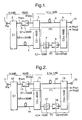
- FIG 1 shows the configuration of the feedforward amplifier. This illustrated feedforward amplifier is what is obtained by applying the present invention to the feedforward amplifier shown in Figure 6.
- the feedforward amplifier of this embodiment is provided between an input terminal 1 and an output terminal 10 with a first directional coupler 2, a main amplifier 3, a first delay line 4, a second directional coupler 5, a second delay line 6, a band-pass filter 7, an auxiliary amplifier 8, and a third directional coupler 9.
- the feedforward amplifier of this embodiment is similar in configuration and operation to the feedforward amplifier shown in Figure 6.
- the detailed explanation that follows will therefore focus on the points in which the feedforward amplifier differs in structure and operation from that shown in Figure 6.
- the distortion components detected by the second directional coupler 5 are output to the band-pass filter 7, passed through the band-pass filter 7 and forwarded to the auxiliary amplifier 8.
- the band-pass filter 7 passes mainly those of the distortion components received from the second directional coupler 5 that are present in a prescribed band and reduces components outside the prescribed band. Owing to this characteristic of the band-pass filter 7, the amount (power) of components outside the prescribed band passing through the band-pass filter 7 is small.
- the band in which signals are passed by the band-pass filter 7 (the filter pass band) is, for example, set to be the same as the prescribed band.
- a band including the transmit band and having a width of several times the transmit band is used as the prescribed band.
- the prescribed band in this embodiment is a band centered on the transmit band and extending to the same width on either side of the transmit band so as to have an overall width that is a number of times that of the transmit band.
- the explanation of the feedforward amplifier will for simplicity be made on the assumption that the frequency characteristics of the directional couplers 2, 5 and 9 and the auxiliary amplifier 8 are the same inside and outside the transmit band and the same inside and outside the prescribed band.
- the power Pno2 of the noise output from the output terminal 10 via the second path (2) is represented by Equation 5.
- Equation 6 power -Pno of the out-of-prescribed-band noise output from the output terminal 10 of the feedforward amplifier is represented by Equation 6.
- the level (power) of the distortion component ahead of the auxiliary amplifier 8 is relatively low, a relatively small filter can be used as the band-pass filter 7 and the provision of the band-pass filter 7 causes substantially no change in power consumption relative to that of the conventional feedforward amplifier.
- the feedforward amplifier of this embodiment removes out-of-prescribed-band components among the distortion components at a point upstream of the auxiliary amplifier 8.
- the out-of-prescribed-band noise contained in the amplified signal output from the output terminal 10 can be efficiently reduced and out-of-prescribed-band noise (e.g., noise in a band subject to a strict noise limit) can be diminished more than possible heretofore.
- the transmit signals are signals wirelessly transmitted from a W-CDMA system base station to mobile stations or the like, PHS band noise components present outside the W-CDMA transmit band (and outside the prescribed band) are reduced by the band-pass filter 7, and, as a result, amplified signals with reduced out-of-prescribed-band noise can be wirelessly transmitted from the base station.
- the feedforward amplifier of the present embodiment is installed in the transmitter unit or the like of a W-CDMA system base station or the like, and transmit signals are amplified by the feedforward amplifier, the effect of interference on the bands of other systems such as the PHS system can be efficiently suppressed.
- the function of the first directional coupler 2 constitutes the invention means for dividing a transmit signal
- the main amplifier 3 corresponds to the main amplifier for amplifying one divided signal
- the function of the second directional coupler 5 constitutes the means for combining the amplified signal and the other divided signal to detect distortion components generated in the main amplifier and contained in the amplified signal
- the auxiliary amplifier 8 corresponds to the auxiliary amplifier for amplifying the detected distortion components
- the function of the third directional coupler 9 constitutes the means for combining the amplified distortion components and the amplified signal from the main amplifier to remove those of the distortion components present in a prescribed band from the amplified signal.
- the function of the band-pass filter 7 constitutes the invention filter for reducing the out-of-prescribed-band components among the detected distortion components and the band-pass filter 7 is provided immediately ahead of the auxiliary amplifier 8.
- FIG 2 shows the configuration of the feedforward amplifier.
- This feedforward amplifier is what is obtained by applying the present invention to the feedforward amplifier shown in Figure 6.
- the feedforward amplifier of this embodiment is provided between an input terminal 11 and an output terminal 20 with a first directional coupler 12, a main amplifier 13, a first delay line 14, a second directional coupler 15, a second delay line 16, a band-elimination filter 17, an auxiliary amplifier 18, and a third and directional coupler 9.
- the feedforward amplifier of this embodiment is similar in configuration and operation to the feedforward amplifier shown in Figure 6.
- the configuration of the feedforward amplifier is what is obtained by replacing the band-pass filter 7 provided in the feedforward amplifier of the first embodiment shown in Figure 1 with the band-elimination filter 17.
- the distortion components detected by the second directional coupler 15 are output to the band-elimination filter 17, passed through the band-elimination filter 17 and forwarded to the auxiliary amplifier 18.
- the band-elimination filter 17 reduces out-of-prescribed-band components among the distortion components received from the second directional coupler 15 and passes mainly components present in a prescribed band.
- a band including the transmit band and having a width of several times the transmit band is used as the prescribed band.
- the prescribed band in this embodiment is a band centered on the transmit band and extending to the same width on either side of the transmit band so as to have an overall width that is a number of times that of the transmit band.
- the feedforward amplifier of this second embodiment removes out-of-prescribed-band components among the distortion components at a point upstream of the auxiliary amplifier 18.
- the out-of-prescribed-band noise contained in the amplified signal output from the output terminal 20 can be efficiently reduced and out-of-prescribed-band noise can be diminished more than possible heretofore.
- the function of the band-elimination filter 17 constitutes the invention filter for reducing the out-of-prescribed-band components among the detected distortion components and the band-elimination filter 17 is provided immediately ahead of the auxiliary amplifier 18.
- Figure 3 shows part of the configuration of the feedforward amplifier.
- the illustrated portion includes a second directional coupler 21, a second delay line 22, an auxiliary amplifier 23 composed of multiple amplifiers 23a - 23c, filter 24, and a third directional amplifier 25.
- the feedforward amplifier of this third embodiment is also equipped with an input terminal, an output terminal, a first directional coupler, a main amplifier, and a first delay line.
- the auxiliary amplifier 23 is constituted by combining the amplifiers 23a - 23c, and the filter 24 that reduces out-of-prescribed-band components among the distortion components output from the second directional coupler 21 is incorporated among (intermediate of) the multiple amplifiers 23a - 23c.
- the filter 24 can be any of various types.
- the feedforward amplifier configured in the manner of this third embodiment can, like that of the first embodiment, reduce the out-of-prescribed-band noise contained in the amplified signal output from the output terminal 10.
- Figure 4 shows part of the configuration of the feedforward amplifier.
- the illustrated portion includes a second directional coupler 31, a second delay line 32, an auxiliary amplifier 33, a filter 34, and a third directional amplifier 35.
- the feedforward amplifier of this fourth embodiment is also equipped with an input terminal, an output terminal, a first directional coupler, a main amplifier, and a first delay line.
- the filter 34 that reduces out-of-prescribed-band components among the distortion components output from the second directional coupler 31 is installed behind the auxiliary amplifier 33.
- the filter 34 can be any of various types.
- the feedforward amplifier configured in the manner of this fourth embodiment can, like that of the first embodiment, reduce the out-of-prescribed-band noise contained in the amplified signal output from the output terminal 10.
- delay lines 4, 6, 14, 16, 22 and 32 are used as the signal delay means in the first to fourth embodiments set out in the foregoing, other means, such as delay filters, can be used instead.
- the configuration obtained by replacing the second delay line 6 shown in Figure 1, the second delay line 16 shown in Figure 2, the second delay line 22 shown in Figure 3 or the second delay line 32 shown in Figure 4 with a delay filter enables further reduction of out-of-prescribed-band noise.
- the horizontal axis of the graph is scaled for frequency and the vertical axis for the level (power) characteristic (transmission characteristic) of a signal passing through the delay filter.
- the delay filter having the transmission characteristic shown by the graph of Figure 5 is installed in the first path (1) of the foregoing first to fourth embodiments, i.e., is provided between the second directional coupler 5 and third directional coupler 9 in Figure 1, between the second directional coupler 15 and the third directional coupler 19 in Figure 2, between the second directional coupler 21 and the third directional amplifier 25 in Figure 3, or between the second directional coupler 31 and the third directional amplifier 35 in Figure 4, and is used to filter the amplified signal from the main amplifier 3 or 13, the power Pno1 of the distortion component noise output from the output terminal 10 or 20 via the first path (1) is represented by Equation 7.
- Equation 7 the power Pno of the out-of-prescribed-band noise output from the output terminal 10 or 20 of the feedforward amplifier equipped with the delay filter is represented by Equation 7.
- the configuration of the feedforward amplifier according to this invention is not limited to that set out in the foregoing and any of various other configurations can be adopted instead. It should also be noted that the present invention can be implemented in the form of a method of executing the processing of the present invention or a program for implementing the method.
- the various types of processing performed in the feedforward amplifier according to this invention may be constituted by being implemented in hardware resources equipped with a processor and memory and the like, for example, being controlled by means of the processor executing a control program stored in ROM. Further, the various functional means for executing this processing may also be constituted as independent physical circuits.
- the present invention may also be understood as- the aforesaid program per se or as a floppy disk, CD-ROM or other computer-readable recording media in which the control program is stored, so that the processing according to the present invention can be implemented by loading said control program from the recording medium into a computer and executing the program by a processor.
- the feedforward amplifier of the present invention divides the signal to be amplified, amplifies one divided signal with a main amplifier, combines the amplified signal and the other divided signal to detect distortion components generated in the main amplifier and contained in the amplified signal, amplifies the detected distortion components with an auxiliary amplifier, and combines the amplified distortion components and the amplified signal from the main amplifier to remove those of the distortion components present in a prescribed band from the amplified signal, and in this process the feedforward amplifier reduces out-of-prescribed-band components contained in the detected distortion components with a filter provided ahead of, intermediate of or behind the auxiliary amplifier, thereby improving the characteristics of the out-of-prescribed-band noise contained in the amplified signal from the main amplifier relative to what has been possible with the conventional feedforward amplifier.
Landscapes
- Physics & Mathematics (AREA)
- Nonlinear Science (AREA)
- Engineering & Computer Science (AREA)
- Power Engineering (AREA)
- Amplifiers (AREA)
- Transmitters (AREA)
Abstract
Description
Claims (10)
- A feedforward amplifier that divides a signal to be amplified, amplifies one divided signal with a main amplifier, combines the amplified signal and another divided signal to detect distortion components generated in the main amplifier and contained in the amplified signal, amplifies the detected distortion components with an auxiliary amplifier, and combines the amplified distortion components and the amplified signal from the main amplifier to remove those of the distortion components present in a prescribed band from the amplified signal, which feedforward amplifier comprises:a filter that reduces out-of-prescribed-band components contained in the detected distortion components.
- A feedforward amplifier according to claim 1, wherein the filter is provided ahead of the auxiliary amplifier.
- A feedforward amplifier according to claim 1, wherein the auxiliary amplifier is constituted by combining multiple amplifier elements and the filter is provided intermediate of the multiple amplifier elements constituting the auxiliary amplifier.
- A feedforward amplifier according to claim 1, wherein the filter is provided behind the auxiliary amplifier.
- A feedforward amplifier according to any of claims 1 to 4, further comprising a filter that reduces the out-of-prescribed-band components contained in the amplified signal from the main amplifier combined with the amplified distortion components.
- A feedforward amplifier according to claim 1, which comprises:a distortion detection loop including a first directional coupler that divides the signal to be amplified, a main amplifier that amplifies one divided signal, first delay means that delays another divided signal, and a second directional coupler that combines an amplified signal from the main amplifier and the other divided signal delayed by the first delay means to detect distortion components generated in the main amplifier and contained in the amplified signal; anda distortion removal loop including second delay means that delays the amplified signal from the main amplifier, an auxiliary amplifier that amplifies the distortion components detected by the second directional coupler, a third directional coupler that combines amplified distortion components from the auxiliary amplifier and the amplified signal delayed by the second delay means to remove those of the distortion components present in a prescribed band from the amplified signal, and a filter that reduces out-of-prescribed-band components contained in the distortion components detected by the second directional coupler.
- A feedforward amplifier according to claim 2, which comprises:a distortion detection loop including a first directional coupler that divides the signal to be amplified, a main amplifier that amplifies one divided signal, first delay means that delays another divided signal, and a second directional coupler that combines an amplified signal from the main amplifier and the other divided signal delayed by the first delay means to detect distortion components generated in the main amplifier and contained in the amplified signal; anda distortion removal loop including second delay means that delays the amplified signal from the main amplifier, a filter that reduces out-of-prescribed-band components contained in the distortion components detected by the second directional coupler, an auxiliary amplifier that amplifies the distortion components from the filter, and a third directional coupler that combines amplified distortion components from the auxiliary amplifier and the amplified signal delayed by the second delay means to remove those of the distortion components present in a prescribed band from the amplified signal.
- A feedforward amplifier according to claim 3, which comprises:a distortion detection loop including a first directional coupler that divides the signal to be amplified, a main amplifier that amplifies one divided signal, first delay means that delays another divided signal, and a second directional coupler that combines an amplified signal from the main amplifier and the other divided signal delayed by the first delay means to detect distortion components generated in the main amplifier and contained in the amplified signal; anda distortion removal loop including second delay means that delays the amplified signal from the main amplifier, an auxiliary amplifier constituted by combining multiple amplifier elements that amplifies the distortion components detected by the second directional coupler, a filter provided intermediate of the multiple amplifier elements constituting the auxiliary amplifier that reduces out-of-prescribed-band components contained in the distortion components detected by the second directional coupler, and a third directional coupler that combines amplified distortion components from the auxiliary amplifier and the amplified signal delayed by the second delay means to remove those of the distortion components present in a prescribed band from the amplified signal.
- A feedforward amplifier according to claim 4, which comprises:a distortion detection loop including a first directional coupler that divides the signal to be amplified, a main amplifier that amplifies one divided signal, first delay means that delays another divided signal, and a second directional coupler that combines an amplified signal from the main amplifier and the other divided signal delayed by the first delay means to detect distortion components generated in the main amplifier and contained in the amplified signal; anda distortion removal loop including second delay means that delays the amplified signal from the main amplifier, an auxiliary amplifier that amplifies the distortion components detected by the second directional coupler, a filter that reduces out-of-prescribed-band components contained in the amplified distortion components from the auxiliary amplifier, and a third directional coupler that combines amplified distortion components from the filter and the amplified signal delayed by the second delay means to remove those of the distortion components present in a prescribed band from the amplified signal.
- A feedforward amplifier according to any of claims 6 to 9, wherein the second delay means is a filter that reduces the out-of-prescribed-band components contained in the amplified signal from the main amplifier.
Applications Claiming Priority (4)
| Application Number | Priority Date | Filing Date | Title |
|---|---|---|---|
| JP2001213316 | 2001-07-13 | ||
| JP2001213316 | 2001-07-13 | ||
| JP2002141184 | 2002-05-16 | ||
| JP2002141184A JP3662552B2 (en) | 2001-07-13 | 2002-05-16 | Feed forward amplifier |
Publications (2)
| Publication Number | Publication Date |
|---|---|
| EP1276227A2 true EP1276227A2 (en) | 2003-01-15 |
| EP1276227A3 EP1276227A3 (en) | 2004-06-09 |
Family
ID=26618666
Family Applications (1)
| Application Number | Title | Priority Date | Filing Date |
|---|---|---|---|
| EP20020254877 Withdrawn EP1276227A3 (en) | 2001-07-13 | 2002-07-11 | Feedforward amplifier |
Country Status (4)
| Country | Link |
|---|---|
| US (1) | US20030011428A1 (en) |
| EP (1) | EP1276227A3 (en) |
| JP (1) | JP3662552B2 (en) |
| CN (1) | CN100426706C (en) |
Families Citing this family (15)
| Publication number | Priority date | Publication date | Assignee | Title |
|---|---|---|---|---|
| US6850115B2 (en) * | 2002-08-26 | 2005-02-01 | Powerwave Technologies, Inc. | Enhanced efficiency LDMOS based feed forward amplifier |
| JP2005176195A (en) * | 2003-12-15 | 2005-06-30 | Nec Corp | Feedforward amplifier |
| US7218237B2 (en) | 2004-05-27 | 2007-05-15 | Lawrence Kates | Method and apparatus for detecting water leaks |
| US7623028B2 (en) * | 2004-05-27 | 2009-11-24 | Lawrence Kates | System and method for high-sensitivity sensor |
| US7561057B2 (en) * | 2004-05-27 | 2009-07-14 | Lawrence Kates | Method and apparatus for detecting severity of water leaks |
| US7142107B2 (en) | 2004-05-27 | 2006-11-28 | Lawrence Kates | Wireless sensor unit |
| US7228726B2 (en) * | 2004-09-23 | 2007-06-12 | Lawrence Kates | System and method for utility metering and leak detection |
| JP2006279249A (en) * | 2005-03-28 | 2006-10-12 | Hitachi Kokusai Electric Inc | Feedforward amplifier |
| US7336168B2 (en) * | 2005-06-06 | 2008-02-26 | Lawrence Kates | System and method for variable threshold sensor |
| EP1905200A1 (en) | 2005-07-01 | 2008-04-02 | Terahop Networks, Inc. | Nondeterministic and deterministic network routing |
| US7230528B2 (en) * | 2005-09-20 | 2007-06-12 | Lawrence Kates | Programmed wireless sensor system |
| US7142123B1 (en) * | 2005-09-23 | 2006-11-28 | Lawrence Kates | Method and apparatus for detecting moisture in building materials |
| US7528711B2 (en) * | 2005-12-19 | 2009-05-05 | Lawrence Kates | Portable monitoring unit |
| WO2009151877A2 (en) | 2008-05-16 | 2009-12-17 | Terahop Networks, Inc. | Systems and apparatus for securing a container |
| CN105243041B (en) * | 2015-09-30 | 2018-08-28 | 英特格灵芯片(天津)有限公司 | A kind of feed forward equalization preemphasis circuit and processing method, usb driver |
Family Cites Families (4)
| Publication number | Priority date | Publication date | Assignee | Title |
|---|---|---|---|---|
| US4394624A (en) * | 1981-08-07 | 1983-07-19 | The United States Of America As Represented By The Secretary Of The Navy | Channelized feed-forward system |
| JP3662138B2 (en) * | 1998-03-16 | 2005-06-22 | 株式会社日立国際電気 | amplifier |
| EP1030441A3 (en) * | 1999-02-16 | 2004-03-17 | Matsushita Electric Industrial Co., Ltd. | Feedforward amplifier |
| GB2352570B (en) * | 1999-07-28 | 2003-12-24 | Wireless Systems Int Ltd | Distortion reduction |
-
2002
- 2002-05-16 JP JP2002141184A patent/JP3662552B2/en not_active Expired - Fee Related
- 2002-06-28 CN CNB021244707A patent/CN100426706C/en not_active Expired - Fee Related
- 2002-07-10 US US10/191,053 patent/US20030011428A1/en not_active Abandoned
- 2002-07-11 EP EP20020254877 patent/EP1276227A3/en not_active Withdrawn
Also Published As
| Publication number | Publication date |
|---|---|
| CN1398072A (en) | 2003-02-19 |
| JP3662552B2 (en) | 2005-06-22 |
| CN100426706C (en) | 2008-10-15 |
| EP1276227A3 (en) | 2004-06-09 |
| US20030011428A1 (en) | 2003-01-16 |
| JP2003092519A (en) | 2003-03-28 |
Similar Documents
| Publication | Publication Date | Title |
|---|---|---|
| EP1276227A2 (en) | Feedforward amplifier | |
| EP1710920A1 (en) | Receiving modulated radio signals | |
| US6801083B2 (en) | Feedforward amplifier | |
| KR100329262B1 (en) | A cancellation circuit of inter-modulation product by RF passive component in repeater | |
| US6888404B2 (en) | Multicarrier amplifying device | |
| US8010055B2 (en) | Method and apparatus for RF communication system signal to noise ratio improvement | |
| EP1505744A1 (en) | Adaptive antenna transmission apparatus, and base station apparatus using the same | |
| EP1189339A1 (en) | System and method for producing a pilot signal in a distortion reduction system | |
| US6940346B2 (en) | Feedforward amplifier, communication apparatus, feedforward amplification method, program and medium | |
| KR100592588B1 (en) | Time Division Duplex System using Feedforward Linear Amplifier for Improved Transceiver Separation | |
| KR20040032672A (en) | Received using forward cancellation techniques | |
| KR100764429B1 (en) | Relay system and its driving method | |
| EP1628392A1 (en) | Amplification device | |
| KR20020061727A (en) | The transmittion power amplifier in mobile communication system | |
| KR100329639B1 (en) | Base station recieption transceiver jamming eliminator of the mobile communication system | |
| KR100519700B1 (en) | Optimized loop control method for a linear power amplifier | |
| JP2000156657A (en) | Near disturbance wave eliminating device | |
| KR101405890B1 (en) | Frequency division duplexing apparatus and antenna apparatus for controlling and eliminating passive intermodulation | |
| JP2000269879A (en) | Relay amplifier | |
| JP2855989B2 (en) | High frequency signal amplifier circuit | |
| KR100924793B1 (en) | Filter module suppresses WCDA and WIR-based interference signals | |
| JPH10200340A (en) | Feedforward amplifier | |
| JP2002223131A (en) | Feedforward amplifier | |
| JP2002158596A (en) | Receiver front end | |
| JP2002185266A (en) | Feedforward amplifier with gain monitoring function |
Legal Events
| Date | Code | Title | Description |
|---|---|---|---|
| PUAI | Public reference made under article 153(3) epc to a published international application that has entered the european phase |
Free format text: ORIGINAL CODE: 0009012 |
|
| AK | Designated contracting states |
Kind code of ref document: A2 Designated state(s): AT BE BG CH CY CZ DE DK EE ES FI FR GB GR IE IT LI LU MC NL PT SE SK TR |
|
| AX | Request for extension of the european patent |
Free format text: AL;LT;LV;MK;RO;SI |
|
| PUAL | Search report despatched |
Free format text: ORIGINAL CODE: 0009013 |
|
| AK | Designated contracting states |
Kind code of ref document: A3 Designated state(s): AT BE BG CH CY CZ DE DK EE ES FI FR GB GR IE IT LI LU MC NL PT SE SK TR |
|
| AX | Request for extension of the european patent |
Extension state: AL LT LV MK RO SI |
|
| AKX | Designation fees paid | ||
| REG | Reference to a national code |
Ref country code: DE Ref legal event code: 8566 |
|
| STAA | Information on the status of an ep patent application or granted ep patent |
Free format text: STATUS: THE APPLICATION IS DEEMED TO BE WITHDRAWN |
|
| 18D | Application deemed to be withdrawn |
Effective date: 20050202 |