EP1276219A1 - Three-phase rectifier - Google Patents
Three-phase rectifier Download PDFInfo
- Publication number
- EP1276219A1 EP1276219A1 EP01914173A EP01914173A EP1276219A1 EP 1276219 A1 EP1276219 A1 EP 1276219A1 EP 01914173 A EP01914173 A EP 01914173A EP 01914173 A EP01914173 A EP 01914173A EP 1276219 A1 EP1276219 A1 EP 1276219A1
- Authority
- EP
- European Patent Office
- Prior art keywords
- phase
- equal
- capacitor
- phase rectifier
- reactors
- Prior art date
- Legal status (The legal status is an assumption and is not a legal conclusion. Google has not performed a legal analysis and makes no representation as to the accuracy of the status listed.)
- Withdrawn
Links
Images






Classifications
-
- H—ELECTRICITY
- H02—GENERATION; CONVERSION OR DISTRIBUTION OF ELECTRIC POWER
- H02M—APPARATUS FOR CONVERSION BETWEEN AC AND AC, BETWEEN AC AND DC, OR BETWEEN DC AND DC, AND FOR USE WITH MAINS OR SIMILAR POWER SUPPLY SYSTEMS; CONVERSION OF DC OR AC INPUT POWER INTO SURGE OUTPUT POWER; CONTROL OR REGULATION THEREOF
- H02M1/00—Details of apparatus for conversion
- H02M1/42—Circuits or arrangements for compensating for or adjusting power factor in converters or inverters
- H02M1/4208—Arrangements for improving power factor of AC input
- H02M1/4216—Arrangements for improving power factor of AC input operating from a three-phase input voltage
-
- H—ELECTRICITY
- H02—GENERATION; CONVERSION OR DISTRIBUTION OF ELECTRIC POWER
- H02M—APPARATUS FOR CONVERSION BETWEEN AC AND AC, BETWEEN AC AND DC, OR BETWEEN DC AND DC, AND FOR USE WITH MAINS OR SIMILAR POWER SUPPLY SYSTEMS; CONVERSION OF DC OR AC INPUT POWER INTO SURGE OUTPUT POWER; CONTROL OR REGULATION THEREOF
- H02M1/00—Details of apparatus for conversion
- H02M1/12—Arrangements for reducing harmonics from AC input or output
- H02M1/126—Arrangements for reducing harmonics from AC input or output using passive filters
-
- H—ELECTRICITY
- H02—GENERATION; CONVERSION OR DISTRIBUTION OF ELECTRIC POWER
- H02M—APPARATUS FOR CONVERSION BETWEEN AC AND AC, BETWEEN AC AND DC, OR BETWEEN DC AND DC, AND FOR USE WITH MAINS OR SIMILAR POWER SUPPLY SYSTEMS; CONVERSION OF DC OR AC INPUT POWER INTO SURGE OUTPUT POWER; CONTROL OR REGULATION THEREOF
- H02M1/00—Details of apparatus for conversion
- H02M1/42—Circuits or arrangements for compensating for or adjusting power factor in converters or inverters
- H02M1/4208—Arrangements for improving power factor of AC input
- H02M1/4266—Arrangements for improving power factor of AC input using passive elements
-
- Y—GENERAL TAGGING OF NEW TECHNOLOGICAL DEVELOPMENTS; GENERAL TAGGING OF CROSS-SECTIONAL TECHNOLOGIES SPANNING OVER SEVERAL SECTIONS OF THE IPC; TECHNICAL SUBJECTS COVERED BY FORMER USPC CROSS-REFERENCE ART COLLECTIONS [XRACs] AND DIGESTS
- Y02—TECHNOLOGIES OR APPLICATIONS FOR MITIGATION OR ADAPTATION AGAINST CLIMATE CHANGE
- Y02B—CLIMATE CHANGE MITIGATION TECHNOLOGIES RELATED TO BUILDINGS, e.g. HOUSING, HOUSE APPLIANCES OR RELATED END-USER APPLICATIONS
- Y02B70/00—Technologies for an efficient end-user side electric power management and consumption
- Y02B70/10—Technologies improving the efficiency by using switched-mode power supplies [SMPS], i.e. efficient power electronics conversion e.g. power factor correction or reduction of losses in power supplies or efficient standby modes
Definitions
- This invention relates to improvement of a three-phase rectifier.
- the present invention was made in view of the above problems.
- a three-phase rectifier of claim 1 connects between a three-phase power source and a diode rectification circuitry a low frequency filter comprising ⁇ -connection or Y-connection capacitors.
- a three-phase rectifier of claim 2 determines a % impedance of each of the AC reactors to be equal to or greater than 12% and equal to or less than 36%.
- a three-phase rectifier of claim 3 determines an inductance value of each of the AC reactors to be equal to or greater than (V /400) 2 x10m H (where, V is a voltage of the three-phase power supply) and equal to or less than (V/400) 2 x30m H.
- a three-phase rectifier of claim 4 determines a capacitance of the capacitor to be a capacitance so as to determine a resonance period of the AC reactor and the capacitor to be equal to or less than 1 cycle even when load is light
- a three-phase rectifier of claim 5 employs a capacitor included within a common mode filter for high frequency noise removal, as the capacitor.
- a three-phase rectifier of claim 6 employs capacitors including a capacitor included within a common mode filter for high frequency noise removal, as the capacitor.
- a phase of an input current can be advanced by flowing a resonance current to the low frequency filter, consequently lowering in input power factor and lowering in DC voltage are prevented from occurrence, because the low frequency filter is connected between the three phase power source and the diode rectification circuitry.
- higher harmonic currents are reduced to be equal to or less than standard values by the AC reactors.
- the three-phase rectifier of claim 2 When the three-phase rectifier of claim 2 is employed, a high input power factor is maintained in addition to the operation and effect of claim 1, because the % impedance of each of the AC reactors is determined to be equal to or greater than 12% and equal to or less than 36%.
- the higher harmonic currents are determined to be equal to or less than the standard values despite of variation in load in addition to the operation and effect of one of claims 1-3, because the capacitance of the capacitor is determined to be a capacitance so as to determine a resonance period of the AC reactor and the capacitor to be equal to or less than 1 cycle even when load is light.
- capacitors are not needed to be especially provided so that increase in cost is prevented from occurrence in addition to the operation and effect of one of claims 1-4, because the capacitor included within the common mode filter for high frequency noise removal is employed as the capacitor.
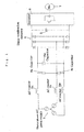
- Fig. 1 is an electric circuit diagram illustrating an embodiment of a three-phase rectifier according to the present invention.
- each one terminal of AC reactors 2u, 2v and 2w is connected to a terminal of each phase 1u, 1v and 1w of a three-phase AC power supply 1.
- Each the other terminal of the AC reactors 2u, 2v and 2w is connected to each input terminal of a diode rectification circuitry 4.
- a smoothing capacitor 5 and an inverter 6 are connected in parallel to one another between output terminals of the diode rectification circuitry 4.
- each of capacitors (filter capacitors) 8u, 8v and 8w is connected between lines, each being between each of the other terminals of the AC reactors 2u, 2v and 2w and each of the input terminals of the diode rectification circuitry 4.
- an output from the inverter 6 is supplied to a motor 7.
- the filter capacitors 8u, 8v and 8w may be connected to one the other in Y-connection.
- a %-impedance of each of three-phase AC reactors is determined to be equal to or greater than 12% and equal to or less than 36%, despite of rating power of the three-phase rectification circuitry. Further, the inductance value of each of the AC reactors is determined to be equal to or greater than (V/400) 2 x10m H and equal to or less than (V/400) 2 x30m H, where the rating power of the three-phase rectification circuitry is supposed to be about 6kW and the voltage of the three-phase power supply is supposed to be V
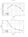
- a low frequency filter comprising AC reactors and filter capacitors in ⁇ -connection or Y- connection is connected between the three-phase power supply 1 and the diode rectification circuitry 4. Therefore, the phase of the input current is advanced by the resonance current which flows through the low frequency filter and is illustrated in Fig. 2(C) (refer to Fig. 2(B) and Fig. 3(C) which illustrates the phase of the input current of the conventional three-phase rectifier). And, the input power factor is improved, as illustrated with (A) in Fig. 4, with respect to the input power factor of the conventional three-phase rectifier (refer to (B) in Fig. 4).
- the DC voltage is increased, as illustrated with (A) in Fig. 5, with respect to the DC voltage of the conventional three-phase rectifier (refer to (B) in Fig. 5). In other words, lowering in input power factor and lowering in DC voltage are prevented from occurrence.
- the limit values of higher harmonic currents are determined for devices having input currents which are equal to or less than 16A per phase, when the power voltage of the three-phase power supply is 400V grade.
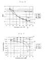
- the inductance value of each AC reactors should be determined to be equal to or greater than 23mH, as is understood from Fig. 6.
- standards (class E) for professional devices, which is determined by moderating the class A, are under consideration, to satisfy the moderated standards, the inductance value of each AC reactors should be determined to be equal to or greater than 10mH.
- (A), (B) and (C) in Fig. 6 represent fifth harmonic current-inductance value characteristics for cases that the capacitance of the filter capacitor is determined to be 1 ⁇ F, 3 ⁇ F, and 10 ⁇ F, respectively, and the operation is carried out with the rating power.
- a high input power factor of equal to or greater than 80% is maintained despite of the capacitance of the filter capacitor by determining the inductance value of the AC reactor to be 30mH, as is understood from Fig. 7 which illustrates input power factor-inductance value characteristics in cases that the capacitance of the filter capacitor at the rating power is determined to be 1 ⁇ F ⁇ refer to (A) in Fig. 7 ⁇ , 3 ⁇ F ⁇ refer to (B) in Fig. 7 ⁇ and 10 ⁇ F ⁇ refer to (C) in Fig. 7 ⁇ .
- Fig. 8 is a diagram illustrating an input power factor-input power characteristics corresponding to cases where power voltage of three phase AC power supply is 400 V grade and 200 V grade
- Fig. 9 is a diagram illustrating a fifth harmonic current generation rate with respect to the fundamental wave-input power characteristics corresponding to cases where power voltage of three phase AC power supply is 400 V grade and 200 V grade
- Fig. 10 is a diagram illustrating each of higher harmonic current generation rate with respect to the fundamental wave corresponding to cases where power voltage of three phase AC power supply is 400 V grade and 200 V grade.
- black circles represent the case of 400V grade, while black squares represent the case of 200V grade.
- black sticks represent the case of 400V grade, while white sticks represent the case of 200V grade.
- Fig. 11 is a diagram illustrating higher harmonics generation rate with respect to the fundamental wave in cases that the input power is 6kW and 12kw.
- White sticks correspond to the 6kW case, while black sticks correspond to the 12kW case.
- the rating power of the three-phase rectifier is 12kW
- the inductance value is determined to have a half value (the filter capacitor has a twice value) so as to make the AC reactor to have the same capacitance as that of the AC reactor corresponding to the case that the rating power is 6kW.
- the higher harmonic current generation rate with respect to the input power factor and the fundamental wave is determined to be equal to that of the other case, as illustrated in Figs. 8-10, by determining the inductance value to have a 1/4 value (the filter capacitor has a 4 times value) so as to make the AC reactor to have the same capacitance as that of the AC reactor corresponding to the case that the power voltage is 400V grade.
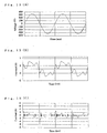
- Figs. 12(A)-(C) are diagrams illustrating a power supply voltage wave pattern ⁇ refer to Fig. 12(A) ⁇ , an input current wave pattern ⁇ refer to Fig. 12(B) ⁇ , and a filter capacitor current wave pattern ⁇ refer to Fig.
- Figs. 13(A)-(C) are diagrams illustrating a power supply voltage wave pattern ⁇ refer to Fig. 13(A) ⁇ , an input current wave pattern ⁇ refer to Fig. 13(B) ⁇ , and a filter capacitor current wave pattern ⁇ refer to Fig. 13(C) ⁇ where the capacitance of the filter capacitor is determined to be 3 ⁇ F.
- Fig. 14 is a diagram illustrating relationships between harmonic currents at light load (refer to black sticks in Fig. 14) and rating load (refer to white sticks in Fig. 14) and harmonic current standard values (refer to a solid line in Fig.
- Fig. 15 is a diagram illustrating relationships between harmonic currents at light load (refer to black sticks in Fig. 15) and rating load (refer to white sticks in Fig. 15) and harmonic current standard values (refer to a solid line in Fig. 14) where the capacitance of the filter capacitor is determined to be 3 ⁇ F.
- Fig. 16 is a diagram illustrating relationships between a capacitance of the filter capacitor and an inductance value of the AC reactor for determining resonance frequency to be 0.4kHz ⁇ refer to (A) in Fig. 16 ⁇ , 0.6kHz ⁇ refer to (B) in Fig.
- higher harmonic current values are determined to be equal to or less than the higher harmonic current standard values even when the load is light, by determining the capacitance of the filter capacitor and the inductance value of the AC reactor to have values corresponding to the above region with respect to (E) in Fig. 16.
- Fig. 17 is an electric circuit diagram illustrating another embodiment of a three-phase rectifier according to the present invention.
- each one terminal of AC reactors 2u, 2v and 2w is connected to a terminal of each phase 1u, 1v and 1w of a three-phase AC power supply 1.
- Each the other terminal of the AC reactors 2u, 2v and 2w and a neutral point 1n are connected to each input terminal of a common mode filter 3.
- Each output terminal of the common mode filter 3 is connected to each input terminal of a diode rectification circuitry 4.
- a smoothing capacitor 5 and an inverter 6 are connected in parallel to one another between output terminals of the diode rectification circuitry 4. Also, an output from the inverter 6 is supplied to a motor 7.
- A%-impedance of each of three-phase AC reactors is determined to be equal to or greater than 12% and equal to or less than 36%, despite of rating power of the three-phase rectification circuitry. Further, the inductance value of each of the AC reactors is determined to be equal to or greater than (V/400) 2 x10m H and equal to or less than (V/400) 2 x30m H, where the rating power of the three-phase rectification circuitry is supposed to be about 6kW and the voltage of the three-phase power supply is supposed to be V
- Fig. 18 is an electric circuit diagram illustrating an example of an arrangement of a common mode filter.
- each pair of high frequency noise removal reactors 31u, 31v, 31w, 31n, 32u, 32v, 32w and 32n are connected in series to one another to each input terminal.
- Each of first capacitors 33u, 33v, 33w and 33n is connected between lines, each of which connecting each of the input terminal and each of the input terminal side high frequency noise removal reactors 31u, 31v, 31w, 31n.
- Each of second capacitors 34u, 34v, 34w and 34n is connected between each line and the ground, each line connecting each pair of high frequency noise removal reactors 31u, 31v, 31w, 31n, 32u, 32v, 32w, and 32n.
- Each of third capacitors 35u, 35v, 35w and 35n is connected between lines, each of which connecting each of the output terminal side high frequency noise removal reactors 32u, 32v, 32w and 32n and each of the output terminal. Only output terminals are connected to the diode rectification circuitry 4, the only output terminal corresponding to input terminals each of which is connected to each of the AC reactors 2u, 2v and 2w.
- each capacitance is determined to satisfy the following equations.
- capacitors and capacitors included within the common mode filter may compose the filter capacitors.
- the invention of claim 1 has characteristic effect such that a phase of an input current can be advanced by flowing a resonance current to the low frequency filter, consequently lowering in input power factor and lowering in DC voltage are prevented from occurrence, and that higher harmonic currents are reduced to be equal to or less than standard values by the AC reactors.
- the invention of claim 2 has characteristic effect such that a high input power factor is maintained in addition to the effect of claim 1.
- the invention of claim 3 has characteristic effect such that a high input power factor is maintained in addition to the effect of claim 1.
- the invention of claim 4 has characteristic effect such that higher harmonic currents are determined to be equal to or less than the standard values despite of variation in load in addition to the effect of one of claims 1-3.
- the invention of claim 5 has characteristic effect such that capacitors are not needed to be especially provided so that increase in cost is prevented from occurrence in addition to the effect of one of claims 1-4.
- the invention of claim 6 has characteristic effect such that increase in cost due to provision of capacitors is suppressed in addition to the effect of one of claims 1-4.
Landscapes
- Engineering & Computer Science (AREA)
- Power Engineering (AREA)
- Rectifiers (AREA)
- Power Conversion In General (AREA)
- Inverter Devices (AREA)
Abstract
Description
C1=C2=C3=C4=C9=C10=C11=C12=Cx
C5=C6=C7=C8=Cy
Cuv=C1 · C2/(C1+C2)+C9 • C10/(C9+C10)=Cx
Claims (6)
- A three-phase rectifier comprising:A three-phase AC power supply (1);A diode rectification circuitry (4); andA low frequency filter connected between the three-phase AC power supply (1) and the diode rectification circuitry (4), the low frequency filter consisting of AC reactors (2u)(2v)(2w) and Δ-connection or Y-connection capacitors (8u)(8v)(8w).
- A three-phase rectifier as set forth in claim 1, wherein %- impedance of each of the AC reactors (2u)(2v)(2w) is determined to be equal to or greater than 12% and to be equal to or less than 36%.
- A three-phase rectifier as set forth in claim 1, wherein the inductance value of each of the AC reactors is determined to be equal to or greater than (V/400)2x10m H (where, V is a voltage of the three-phase power supply) and equal to or less than (V/400)2x30m H.
- A three-phase rectifier as set forth in one of claims 1-3, a capacitance of the capacitor is determined to be a capacitance so as to determine a resonance period of the AC reactor and the capacitor to be equal to or less than 1 cycle even when load is light.
- A three-phase rectifier as set forth in one of claims 1-4, wherein the capacitor comprises a capacitor included within a common mode filter for high frequency noise removal.
- A three-phase rectifier as set forth in one of claims 1-4, wherein the capacitor comprises capacitors including a capacitor included within a common mode filter for high frequency noise removal.
Applications Claiming Priority (3)
| Application Number | Priority Date | Filing Date | Title |
|---|---|---|---|
| JP2000081802A JP2001268913A (en) | 2000-03-17 | 2000-03-17 | Three-phase rectifier |
| JP2000081802 | 2000-03-17 | ||
| PCT/JP2001/002139 WO2001069770A1 (en) | 2000-03-17 | 2001-03-16 | Three-phase rectifier |
Publications (2)
| Publication Number | Publication Date |
|---|---|
| EP1276219A1 true EP1276219A1 (en) | 2003-01-15 |
| EP1276219A4 EP1276219A4 (en) | 2004-10-06 |
Family
ID=18598688
Family Applications (1)
| Application Number | Title | Priority Date | Filing Date |
|---|---|---|---|
| EP01914173A Withdrawn EP1276219A4 (en) | 2000-03-17 | 2001-03-16 | THREE-PHASE STRAIGHTENING DEVICE |
Country Status (4)
| Country | Link |
|---|---|
| EP (1) | EP1276219A4 (en) |
| JP (1) | JP2001268913A (en) |
| AU (1) | AU3954101A (en) |
| WO (1) | WO2001069770A1 (en) |
Cited By (12)
| Publication number | Priority date | Publication date | Assignee | Title |
|---|---|---|---|---|
| CN103138544A (en) * | 2011-11-29 | 2013-06-05 | 永济新时速电机电器有限责任公司 | Output filter device and power conversion device of inverter |
| EP2485382A4 (en) * | 2009-09-28 | 2017-01-04 | Daikin Industries, Ltd. | Power converter |
| US10396695B2 (en) | 2017-04-18 | 2019-08-27 | General Electric Company | Method for protecting an electrical power system |
| WO2019206289A1 (en) * | 2018-04-28 | 2019-10-31 | 华为技术有限公司 | Inverter, power generation system, and method for inhibiting the distortion of harmonic waves |
| US10587121B2 (en) | 2017-05-23 | 2020-03-10 | General Electric Company | Electrical power systems and subsystems |
| US10763674B2 (en) | 2017-09-29 | 2020-09-01 | General Electric Company | System and method for controlling cluster-based wind farms |
| US10778112B2 (en) | 2018-04-04 | 2020-09-15 | General Electric Company | DFIG converter with active filter |
| US10784689B2 (en) | 2017-05-08 | 2020-09-22 | General Electric Company | Electrical power systems and methods using distortion filters |
| US10784685B2 (en) | 2017-05-08 | 2020-09-22 | General Electric Company | Electrical power systems and subsystems |
| US10951030B2 (en) | 2017-05-05 | 2021-03-16 | General Electric Company | System and method for reactive power control of a wind farm |
| US11081891B2 (en) | 2017-05-05 | 2021-08-03 | General Electric Company | Electrical power systems having reactive power and harmonic support components |
| US11736056B2 (en) | 2019-05-30 | 2023-08-22 | General Electric Company | System and method for controlling harmonics in a renewable energy power system |
Families Citing this family (5)
| Publication number | Priority date | Publication date | Assignee | Title |
|---|---|---|---|---|
| US6567283B2 (en) | 2001-03-30 | 2003-05-20 | Youtility Inc. | Enhanced conduction angle power factor correction topology |
| JP4939819B2 (en) * | 2006-02-28 | 2012-05-30 | 株式会社東芝 | Three-phase rectifier |
| JP5127032B2 (en) * | 2007-04-19 | 2013-01-23 | パナソニック株式会社 | Capacitor drop power supply circuit and power control device |
| JP2009142002A (en) * | 2007-12-04 | 2009-06-25 | Panasonic Corp | Power supply |
| CN105610310B (en) * | 2015-12-28 | 2018-12-21 | 深圳市库马克新技术股份有限公司 | Transducer drive circuit and its method for detecting short circuit |
Family Cites Families (8)
| Publication number | Priority date | Publication date | Assignee | Title |
|---|---|---|---|---|
| DE2950411C2 (en) * | 1979-12-14 | 1986-07-03 | Patent-Treuhand-Gesellschaft Fuer Elektrische Gluehlampen Mbh, 8000 Muenchen | Rectifier device with filtered output voltage |
| JPH01214265A (en) * | 1988-02-23 | 1989-08-28 | Fuji Electric Co Ltd | Output voltage control device for current type converter device |
| JP2869498B2 (en) * | 1990-09-10 | 1999-03-10 | 株式会社日立製作所 | Power converter |
| JP3195105B2 (en) * | 1993-02-26 | 2001-08-06 | 株式会社東芝 | DC power supply circuit for multi-phase input |
| JP2922844B2 (en) * | 1996-04-19 | 1999-07-26 | 日立金属株式会社 | Apparatus using inverter |
| JPH09312541A (en) * | 1996-05-22 | 1997-12-02 | Shizuki Denki Seisakusho:Kk | Inverter filter unit |
| JP3658482B2 (en) * | 1997-01-20 | 2005-06-08 | 株式会社東芝 | Inverter device |
| JP4106496B2 (en) * | 1997-12-26 | 2008-06-25 | 株式会社安川電機 | Inverter common mode voltage / current suppression method and apparatus |
-
2000
- 2000-03-17 JP JP2000081802A patent/JP2001268913A/en active Pending
-
2001
- 2001-03-16 WO PCT/JP2001/002139 patent/WO2001069770A1/en not_active Ceased
- 2001-03-16 EP EP01914173A patent/EP1276219A4/en not_active Withdrawn
- 2001-03-16 AU AU39541/01A patent/AU3954101A/en not_active Abandoned
Cited By (13)
| Publication number | Priority date | Publication date | Assignee | Title |
|---|---|---|---|---|
| EP2485382A4 (en) * | 2009-09-28 | 2017-01-04 | Daikin Industries, Ltd. | Power converter |
| CN103138544A (en) * | 2011-11-29 | 2013-06-05 | 永济新时速电机电器有限责任公司 | Output filter device and power conversion device of inverter |
| US10396695B2 (en) | 2017-04-18 | 2019-08-27 | General Electric Company | Method for protecting an electrical power system |
| US10951030B2 (en) | 2017-05-05 | 2021-03-16 | General Electric Company | System and method for reactive power control of a wind farm |
| US11081891B2 (en) | 2017-05-05 | 2021-08-03 | General Electric Company | Electrical power systems having reactive power and harmonic support components |
| US10784689B2 (en) | 2017-05-08 | 2020-09-22 | General Electric Company | Electrical power systems and methods using distortion filters |
| US10784685B2 (en) | 2017-05-08 | 2020-09-22 | General Electric Company | Electrical power systems and subsystems |
| US10587121B2 (en) | 2017-05-23 | 2020-03-10 | General Electric Company | Electrical power systems and subsystems |
| US10763674B2 (en) | 2017-09-29 | 2020-09-01 | General Electric Company | System and method for controlling cluster-based wind farms |
| US10778112B2 (en) | 2018-04-04 | 2020-09-15 | General Electric Company | DFIG converter with active filter |
| WO2019206289A1 (en) * | 2018-04-28 | 2019-10-31 | 华为技术有限公司 | Inverter, power generation system, and method for inhibiting the distortion of harmonic waves |
| US11336094B2 (en) | 2018-04-28 | 2022-05-17 | Huawei Technologies Co., Ltd. | Inverter, power generating system, and method for suppressing harmonic distortion of alternating current system |
| US11736056B2 (en) | 2019-05-30 | 2023-08-22 | General Electric Company | System and method for controlling harmonics in a renewable energy power system |
Also Published As
| Publication number | Publication date |
|---|---|
| EP1276219A4 (en) | 2004-10-06 |
| WO2001069770A1 (en) | 2001-09-20 |
| JP2001268913A (en) | 2001-09-28 |
| AU3954101A (en) | 2001-09-24 |
Similar Documents
| Publication | Publication Date | Title |
|---|---|---|
| AU3954101A (en) | Three-phase rectifier | |
| US7187566B2 (en) | Three-phase rectifier | |
| Thomas et al. | Design and performance of active power filters | |
| Redl | Electromagnetic environmental impact of power electronics equipment | |
| JPS6367435B2 (en) | ||
| JPH09294374A (en) | Power supply circuit | |
| Redl | An economical single-phase passive power-factor-corrected rectifier: topology, operation, extensions, and design for compliance | |
| EP0244644A1 (en) | Circuit arrangement for the high-frequency operation of low-pressure discharge lamps | |
| CA2114809A1 (en) | Power factor dc power supply | |
| CN214674885U (en) | EMI filter circuit and system | |
| CN112564538B (en) | Method and device for determining converter parameters | |
| CN1222100C (en) | Great-power switching voltage regulator with no electromagnetic pollution | |
| CN213817575U (en) | A frequency conversion integrated board suitable for wide voltage fluctuations | |
| CN2640123Y (en) | 12 pulse wave commutation frequency converter made of 6 pulse wave commutation frequency converter | |
| Maset et al. | Improved passive solutions to meet IEC 1000-3-2 regulation in low-cost power supplies | |
| CN215300481U (en) | Transform system | |
| Suzuki et al. | Experimental studies on active and passive PFC circuits | |
| CN213125832U (en) | Three-phase passive PFC filter circuit | |
| CN209627232U (en) | Passive three-phase power factor correction device and variable frequency electrical equipment | |
| Borage et al. | Passive techniques for compliance of single-phase rectifiers with IEC 1000-3-2 norms | |
| KR102036580B1 (en) | Improved passive harmonic filter for 3-phase nonlinear load | |
| Anzalchi et al. | A modified higher order power filter for grid-connected renewable energy systems | |
| CN1317859A (en) | Power factor correction circuit for three-phase power supply system | |
| CN105846430B (en) | The passive filter of 110kV or more high-pressure systems and its determining method and apparatus | |
| CN222620892U (en) | Filter circuit of valve power amplifier switching power supply |
Legal Events
| Date | Code | Title | Description |
|---|---|---|---|
| PUAI | Public reference made under article 153(3) epc to a published international application that has entered the european phase |
Free format text: ORIGINAL CODE: 0009012 |
|
| 17P | Request for examination filed |
Effective date: 20021104 |
|
| AK | Designated contracting states |
Kind code of ref document: A1 Designated state(s): AT BE CH CY DE DK ES FI FR GB GR IE IT LI LU MC NL PT SE TR |
|
| A4 | Supplementary search report drawn up and despatched |
Effective date: 20040823 |
|
| RIC1 | Information provided on ipc code assigned before grant |
Ipc: 7H 02M 1/12 B Ipc: 7H 02M 1/00 A |
|
| 17Q | First examination report despatched |
Effective date: 20091008 |
|
| STAA | Information on the status of an ep patent application or granted ep patent |
Free format text: STATUS: THE APPLICATION IS DEEMED TO BE WITHDRAWN |
|
| 18D | Application deemed to be withdrawn |
Effective date: 20100219 |