EP1276179A2 - Card connector apparatus capable of receiving plural kinds od cards - Google Patents
Card connector apparatus capable of receiving plural kinds od cards Download PDFInfo
- Publication number
- EP1276179A2 EP1276179A2 EP02014937A EP02014937A EP1276179A2 EP 1276179 A2 EP1276179 A2 EP 1276179A2 EP 02014937 A EP02014937 A EP 02014937A EP 02014937 A EP02014937 A EP 02014937A EP 1276179 A2 EP1276179 A2 EP 1276179A2
- Authority
- EP
- European Patent Office
- Prior art keywords
- card
- slide member
- contact
- connector
- fastening
- Prior art date
- Legal status (The legal status is an assumption and is not a legal conclusion. Google has not performed a legal analysis and makes no representation as to the accuracy of the status listed.)
- Withdrawn
Links
Images







Classifications
-
- H—ELECTRICITY
- H01—ELECTRIC ELEMENTS
- H01R—ELECTRICALLY-CONDUCTIVE CONNECTIONS; STRUCTURAL ASSOCIATIONS OF A PLURALITY OF MUTUALLY-INSULATED ELECTRICAL CONNECTING ELEMENTS; COUPLING DEVICES; CURRENT COLLECTORS
- H01R12/00—Structural associations of a plurality of mutually-insulated electrical connecting elements, specially adapted for printed circuits, e.g. printed circuit boards [PCB], flat or ribbon cables, or like generally planar structures, e.g. terminal strips, terminal blocks; Coupling devices specially adapted for printed circuits, flat or ribbon cables, or like generally planar structures; Terminals specially adapted for contact with, or insertion into, printed circuits, flat or ribbon cables, or like generally planar structures
- H01R12/70—Coupling devices
- H01R12/71—Coupling devices for rigid printing circuits or like structures
-
- G—PHYSICS
- G06—COMPUTING OR CALCULATING; COUNTING
- G06K—GRAPHICAL DATA READING; PRESENTATION OF DATA; RECORD CARRIERS; HANDLING RECORD CARRIERS
- G06K13/00—Conveying record carriers from one station to another, e.g. from stack to punching mechanism
- G06K13/02—Conveying record carriers from one station to another, e.g. from stack to punching mechanism the record carrier having longitudinal dimension comparable with transverse dimension, e.g. punched card
- G06K13/08—Feeding or discharging cards
- G06K13/0868—Feeding or discharging cards using an arrangement for keeping the feeding or insertion slot of the card station clean of dirt, or to avoid feeding of foreign or unwanted objects into the slot
- G06K13/0887—Feeding or discharging cards using an arrangement for keeping the feeding or insertion slot of the card station clean of dirt, or to avoid feeding of foreign or unwanted objects into the slot the arrangement comprising a size filter for filtering out only cards having the proper size
-
- G—PHYSICS
- G06—COMPUTING OR CALCULATING; COUNTING
- G06K—GRAPHICAL DATA READING; PRESENTATION OF DATA; RECORD CARRIERS; HANDLING RECORD CARRIERS
- G06K13/00—Conveying record carriers from one station to another, e.g. from stack to punching mechanism
- G06K13/02—Conveying record carriers from one station to another, e.g. from stack to punching mechanism the record carrier having longitudinal dimension comparable with transverse dimension, e.g. punched card
- G06K13/08—Feeding or discharging cards
-
- G—PHYSICS
- G06—COMPUTING OR CALCULATING; COUNTING
- G06K—GRAPHICAL DATA READING; PRESENTATION OF DATA; RECORD CARRIERS; HANDLING RECORD CARRIERS
- G06K7/00—Methods or arrangements for sensing record carriers, e.g. for reading patterns
- G06K7/0013—Methods or arrangements for sensing record carriers, e.g. for reading patterns by galvanic contacts, e.g. card connectors for ISO-7816 compliant smart cards or memory cards, e.g. SD card readers
- G06K7/0021—Methods or arrangements for sensing record carriers, e.g. for reading patterns by galvanic contacts, e.g. card connectors for ISO-7816 compliant smart cards or memory cards, e.g. SD card readers for reading/sensing record carriers having surface contacts
-
- G—PHYSICS
- G06—COMPUTING OR CALCULATING; COUNTING
- G06K—GRAPHICAL DATA READING; PRESENTATION OF DATA; RECORD CARRIERS; HANDLING RECORD CARRIERS
- G06K7/00—Methods or arrangements for sensing record carriers, e.g. for reading patterns
- G06K7/0013—Methods or arrangements for sensing record carriers, e.g. for reading patterns by galvanic contacts, e.g. card connectors for ISO-7816 compliant smart cards or memory cards, e.g. SD card readers
- G06K7/0034—Methods or arrangements for sensing record carriers, e.g. for reading patterns by galvanic contacts, e.g. card connectors for ISO-7816 compliant smart cards or memory cards, e.g. SD card readers the connector being capable of simultaneously receiving a plurality of cards in the same insertion slot
- G06K7/0043—Methods or arrangements for sensing record carriers, e.g. for reading patterns by galvanic contacts, e.g. card connectors for ISO-7816 compliant smart cards or memory cards, e.g. SD card readers the connector being capable of simultaneously receiving a plurality of cards in the same insertion slot the plurality of cards being cards of different formats, e.g. SD card and memory stick
-
- G—PHYSICS
- G06—COMPUTING OR CALCULATING; COUNTING
- G06K—GRAPHICAL DATA READING; PRESENTATION OF DATA; RECORD CARRIERS; HANDLING RECORD CARRIERS
- G06K7/00—Methods or arrangements for sensing record carriers, e.g. for reading patterns
- G06K7/0013—Methods or arrangements for sensing record carriers, e.g. for reading patterns by galvanic contacts, e.g. card connectors for ISO-7816 compliant smart cards or memory cards, e.g. SD card readers
- G06K7/0047—Methods or arrangements for sensing record carriers, e.g. for reading patterns by galvanic contacts, e.g. card connectors for ISO-7816 compliant smart cards or memory cards, e.g. SD card readers for reading/sensing record carriers having edge contacts
-
- H—ELECTRICITY
- H01—ELECTRIC ELEMENTS
- H01R—ELECTRICALLY-CONDUCTIVE CONNECTIONS; STRUCTURAL ASSOCIATIONS OF A PLURALITY OF MUTUALLY-INSULATED ELECTRICAL CONNECTING ELEMENTS; COUPLING DEVICES; CURRENT COLLECTORS
- H01R12/00—Structural associations of a plurality of mutually-insulated electrical connecting elements, specially adapted for printed circuits, e.g. printed circuit boards [PCB], flat or ribbon cables, or like generally planar structures, e.g. terminal strips, terminal blocks; Coupling devices specially adapted for printed circuits, flat or ribbon cables, or like generally planar structures; Terminals specially adapted for contact with, or insertion into, printed circuits, flat or ribbon cables, or like generally planar structures
- H01R12/70—Coupling devices
- H01R12/71—Coupling devices for rigid printing circuits or like structures
- H01R12/712—Coupling devices for rigid printing circuits or like structures co-operating with the surface of the printed circuit or with a coupling device exclusively provided on the surface of the printed circuit
- H01R12/714—Coupling devices for rigid printing circuits or like structures co-operating with the surface of the printed circuit or with a coupling device exclusively provided on the surface of the printed circuit with contacts abutting directly the printed circuit; Button contacts therefore provided on the printed circuit
-
- H—ELECTRICITY
- H01—ELECTRIC ELEMENTS
- H01R—ELECTRICALLY-CONDUCTIVE CONNECTIONS; STRUCTURAL ASSOCIATIONS OF A PLURALITY OF MUTUALLY-INSULATED ELECTRICAL CONNECTING ELEMENTS; COUPLING DEVICES; CURRENT COLLECTORS
- H01R13/00—Details of coupling devices of the kinds covered by groups H01R12/70 or H01R24/00 - H01R33/00
- H01R13/62—Means for facilitating engagement or disengagement of coupling parts or for holding them in engagement
-
- H—ELECTRICITY
- H01—ELECTRIC ELEMENTS
- H01R—ELECTRICALLY-CONDUCTIVE CONNECTIONS; STRUCTURAL ASSOCIATIONS OF A PLURALITY OF MUTUALLY-INSULATED ELECTRICAL CONNECTING ELEMENTS; COUPLING DEVICES; CURRENT COLLECTORS
- H01R27/00—Coupling parts adapted for co-operation with two or more dissimilar counterparts
Definitions
- the present invention relates to a structure of a card connector apparatus used for small memory cards for use in various portable information terminals, such as a portable telephone or a PC, or memory support equipments such as a digital camera or a digital AV equipment.
- a card connector apparatus is generally used as an expanded recording apparatus of an electronic equipment such as a personal computer or a digital camera.
- an electronic equipment such as a personal computer or a digital camera.
- a storage medium of the card connector apparatus a PC card or a memory card has come into wide use.
- This PC card or memory card is installed in the card connector apparatus to write and read necessary information.
- various kinds of memory cards having different shapes such as a long one, a short one, a thick one, or a thin one, have been developed, and various kinds of card connector apparatuses corresponding to these have been developed.
- the card connector apparatus corresponds to only one kind of memory card, and only one specific memory card has been installed in one card connector apparatus.
- the card connector apparatuses dedicated to the respective memory cards it has been necessary to prepare card connector apparatuses dedicated to the respective memory cards.
- the invention has an object to provide a card connector apparatus which solves the foregoing problems and in which connector terminals are disposed in front and in rear in an insertion direction of a card to enable installation of cards having different lengths, and the respective cards can be smoothly inserted at the time of insertion of the cards.
- another object is to eject the respective cards by a simple structure.
- first means of the invention comprises a housing including a storage portion in which both a first short card and a second long card can be installed, a first connector terminal to be connected with a contact terminal portion of the first card, a second connector terminal to be connected with a contact terminal portion of the second card, the first and the second connector terminals being arranged in two lines in front and in rear in a card insertion direction of the storage portion, a slide member disposed to be movable in the card insertion direction in accordance with insertion of a card, and lock means for locking the slide member at a card installation position, and is characterized in that the slide member is provided with a presser plate portion to come in contact with the first connector terminal at a card ejection position to restrain the first connector terminal from protruding into the storage portion, first fastening portions provided at a front side and not coming in contact with the second card but coming in contact with only a front end portion of the first card, and a second fastening portion provided behind the first fastening
- second means comprises a housing including a storage portion in which both a first short card and a second long card can be installed, a first connector terminal to be connected with a contact terminal portion of the first card, a second connector terminal to be connected with a contact terminal portion of the second card, the first and the second connector terminals being arranged in two lines in front and in rear in a card insertion direction of the storage portion, a slide member disposed to be movable in the card insertion direction in accordance with insertion of a card, and lock means for locking the slide member at a card installation position, and is characterized in that the slide member is divided in two parts in front and in rear to include a first slide member and a second slide member, the first slide member is provided with a presser plate portion to come in contact with the first connector terminal at a card ejection position to restrain the first connector terminal from protruding into the storage portion, and first fastening portions provided at a front side and not coming in contact with the second card but coming in contact with only a front end
- third means is characterized in that the first card is formed to be wide and thin, the second card is formed to be narrower and thicker than the first card, the first fastening portions are formed at opposite positions of inside portions of the slide member, and a width between the first fastening portions is formed to be narrower than a width of the first card and wider than a width of the second card.
- fourth means is characterized in that the slide member is urged toward a card ejecting direction by an urging member, and the lock means is constituted by a heart-shaped cam groove formed at one of the slide member and the housing, and an engagement pin provided at the other and engaging with the heart-shaped cam groove.
- Fig. 1 is a plan view of a card connector apparatus
- Fig. 2 is a plan view of the same in a state where a cover is removed
- Fig. 3 is a plan view of a housing
- Fig. 4 is a plan view of a slide member
- Fig. 5 is a plan view of a first card
- Fig. 6 is a front view of the same
- Fig. 7 is a bottom view of the same
- Fig. 8 is a plan view of a second card
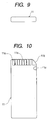
- Fig. 9 is a front view of the same
- Fig. 10 is a bottom view of the same
- Fig. 1 is a plan view of a card connector apparatus
- Fig. 2 is a plan view of the same in a state where a cover is removed
- Fig. 3 is a plan view of a housing
- Fig. 4 is a plan view of a slide member
- Fig. 5 is a plan view of a first card
- Fig. 6 is
- FIG. 11 is a plan view of the card connector apparatus at the time of ejection of the fist card
- Fig. 12 is a longitudinal sectional view of the same
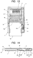
- Fig. 13 is a plan view of the card connector apparatus at the time of installation of the first card
- Fig. 14 is a longitudinal sectional view of the same
- Fig. 15 is a plan view of the card connector apparatus at the time of ejection of the second card
- Fig. 16 is a longitudinal sectional view of the same
- Fig. 17 is a plan view of the card connector apparatus at the time of installation of the second card
- Fig. 18 is a longitudinal sectional view of the same
- Fig. 12 is a longitudinal sectional view of the same
- Fig. 13 is a plan view of the card connector apparatus at the time of installation of the first card
- Fig. 14 is a longitudinal sectional view of the same
- Fig. 15 is a plan view of the card connector apparatus at the time of ejection of the second card
- FIG. 19 is a partial explanatory view showing a state of engagement with a holding member at the time of ejection of the first card
- Fig. 20 is a partial explanatory view showing a state of engagement with the holding member at the time of installation of the first card
- Figs. 21 to 30 show another embodiment
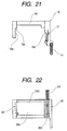
- Fig. 21 is a plan view of a first slide member
- Fig. 22 is a plan view of a second slide member
- Fig. 23 is a plan view of a card connector apparatus at the time of ejection of the first card
- Fig. 24 is a longitudinal sectional view of the same
- Fig 25 is a plan view of the card connector apparatus at the time of installation of the first card
- Fig. 26 is a longitudinal sectional view of the same
- Fig. 21 is a plan view of a first slide member
- Fig. 22 is a plan view of a second slide member
- Fig. 23 is a plan view of a card connector apparatus at the time of ejection
- FIG. 27 is a plan view of the card connector apparatus at the time of ejection of the second card
- Fig. 28 is a longitudinal sectional view of the same
- Fig. 29 is a plan view of the card connector apparatus at the time of installation of the second card
- Fig. 30 is a longitudinal sectional view of the same.
- a housing 1 is made of an insulating material such as synthetic resin and is formed into a square box shape with front and upper openings.
- a storage portion 1a is provided at the center of this housing 1, and a card insertion portion 1b continuous with the storage portion 1a and extending to the front of the housing 1 is formed in the housing 1.
- first and second connector terminals 2 and 3 made of conductive metal material are arranged side by side.
- the first connector terminals 2 are disposed substantially at the center position of the storage portion 1a, and each of them is formed of a flat plate-like base portion, and a connection piece 2a and a contact piece 2b formed in the directions opposite to each other from this base portion and to be bent substantially into a Z shape.
- the first connector terminal 2 is disposed so that the connection piece 2a formed at one end side is exposed to the outside from a first opening portion 1c provided in a bottom portion of the storage portion 1a, and this connection piece 2a is soldered and fixed to a circuit pattern on an external circuit board of an electronic equipment or the like, so that signal transmission is carried out.
- the contact piece 2b formed at the other end side of the base portion of the first connector terminal 2 is disposed to protrude into the storage portion 1a from a second opening portion 1d provided in the bottom portion of the storage portion 1a.
- a contact portion 2c to be connected to a contact terminal portion 10a of a first card 10 described later is formed at the front end side of the contact piece 2b.
- the second connector terminal 3 is disposed to be deeper in the storage portion 1a than the disposal position of the first connector terminal 2, and is formed of a flat plate-like base portion, and a connection piece 3a and a contact piece 3b formed to be bent in directions opposite to each other from this base portion.
- the second connector terminal 3 is disposed so that the connection piece 3a formed at one end side is exposed to the outside from a third opening portion 1e provided in the bottom portion of the storage portion 1a, and this connection piece 3a is soldered and fixed to a circuit pattern on an external circuit board of an electronic equipment or the like, so that signal transmission is carried out.
- the contact piece 3b formed to be bent substantially into a U shape at the other end side of the base portion of the second connector terminal 3 is disposed to protrude into the storage portion 1a.
- a contact portion 3c to be connected to a contact terminal portion 11a of a second card 11 described later is formed at the front end side of the contact piece 3b.
- the card insertion portion 1b is provided with a flat portion 1f made of a plane for guiding plane portions of the first and the second cards 10 and 11 described later, and a pair of guide portions 1g, 1g for guiding side portions of the first and the second cards 10 and 11 described later are formed at both sides of the flat portion 1f.
- the card insertion portion 1b is formed so that the maximum width is substantially equal to the width of the first card 10, and the maximum thickness is substantially equal to the thickness of the second card 11.
- a spring reception portion 1h for receiving a return spring 4 made of a coil spring for urging a slide member 6 described later toward a card ejecting direction is formed at a one side rear portion of the housing 1.
- a press contact portion 1j protruding from the bottom of the storage portion 1a is formed at the other side center portion of the housing 1, and a tongue piece portion 8c of a second holding member 8 fixed to the slide member 6 described later comes in contact with the press contact portion 1j and is supported.
- the slide member 6 is formed of an insulating material such as synthetic resin. This slide member 6 is provided with a first card reception portion 6a positioned on this side and receiving the first card 10 described later and a second card reception portion 6b positioned behind the first card reception portion 6a and receiving the second card 11 described later.
- a pair of fastening portions 6c and 6d to come in contact with both side front end portions of the first card 10 are formed at opposite positions of the inside portions of the first card reception portion 6a.
- the width size between the first fastening portions 6c and 6d is formed to be narrower than the width of the first card 10 and wider than the width of the second card 11.
- a second fastening portion 6e of a cross rail shape to come in contact with the front edge portion of the second card 11 is formed at the front end portion of the second card reception portion 6b.
- a presser plate portion 6f suspended like a cross rail is formed at the front of the first card reception portion 6a.
- the presser plate portion 6f comes in contact with the contact pieces 2b of the first connector terminals 2 to restrain the contact pieces 2b of the first connector terminals 2 from protruding into the storage portion 1a.
- the first and the second holding members 7 and 8 are formed of support piece portions 7a and 8a supported like a cantilever, engagement piece portions 7b and 8b provided at free end sides of the support piece portions 7a and 8a, and tongue piece portions 7c and 8c provided opposite to the engagement piece portions 7b and 8b.
- the tongue piece portions 7c and 8c are provided with inclined surfaces 7d and 8d bent outward at free end sides of the support piece portions 7a and 8a.
- the tongue piece portions 7d and 8d come in contact with press contact portion 9a of a cover member 9 described later and the press contact portion 1j of the housing 1, so that the engagement piece portions 7b and 8b, together with the support piece portions 7a and 8a, are restrained from coming away from the holding concave portions 10e and 11c of the cards.
- the press contact portions 9a and 1j are brought into slide contact with the inclined surfaces 7d and 8d, so that the support piece portions 7a and 8a are curved and urged, and the engagement piece portions 7b and 8b come in elastic contact with the holding concave portions 10e and 11c of the cards.
- the holding members 7 and 8 are constructed by using the spring properties of the metal plates themselves having the spring properties, the card can be held at the installation position by the simple structure.
- the cover member 9 is formed of a conductive metal plate, and is attached to an upper surface side of the housing 1 so as to cover the opening portion of the housing 1 at the upper surface side.
- the press contact portion 9a protruded to the side of the storage portion 1a of the housing 1 by cutting and bending is formed at one side portion of the cover member 9, and the tongue piece portion 7c of the first holding member 7 fixed to the slide member 6 comes in contact with the press contact portion 9a and is supported.
- an urging spring piece 9b for urging the lock pin 5 supported in the housing 1 to be brought into slide contact with the heart-shaped cam groove 6h of the slide member 6 is formed by cutting and bending at a position corresponding to the lock pin 5.
- the cover member 9 is formed so as to cover the upper surfaces of the first and the second connector terminals 2 and 3 disposed in the storage portion 1a of the housing 1, and also functions as a shield plate to prevent intrusion of radiation noise or the like from the outside.
- the first card 10 contains an integrated circuit (IC) in the inside and is widely used as a recording medium.
- IC integrated circuit
- a plurality of contact terminal portions 10a are formed on one surface of the first card 10 at one end side thereof, and the contact terminal portions 10a come in contact with the contact pieces 2b of the first connector terminals 2 disposed in the storage portion 1a of the housing 1, so that various information processings to an externally connected electronic equipment are carried out.
- an inclined cut portion 10b is provided at one corner at the formation side of the contact terminal portion 10a.
- this cut portion 10b and a corner portion at the other end side are engaged with the first fastening portions 6c and 6d of the first card reception portion 6a of the slide member 6, so that the slide member 6 can be moved in the insertion direction in accordance with the insertion of the first card 10.
- a concave groove portion 10c as an identification portion showing write inhibit of a card is formed in one side portion of the first card 10, and a slidable identifier 10d is provided in this concave groove portion 10c.
- the position of the concave groove portion 10c can be changed by sliding and moving this identifier 10d, and in accordance with this position, permission/nonpermission of writing to the card can be changed.
- the holding concave portion 10e is formed at the other side portion of the first card 10.
- the first engagement piece 7 provided at the one side portion of the first card reception portion 6a and having the spring property is engaged with this holding concave portion 10e, so that the first card 10 is held in the first card reception portion 6a of the slide member 6.
- long cut groove portions 10f are formed at both end portions of the first card 10 at the lower surface side, and the maximum width size except for this cut groove portions 10f is formed to be a little wide, whereas the maximum thickness size is formed to be a little thin.
- the second card 11 contains an integrated circuit (IC) in the inside and is widely used as a recording medium.
- IC integrated circuit
- a plurality of contact terminal portions 11a are formed on one surface of the second card 11 at one end side thereof, and the contact terminal portions 11a come in contact with the contact pieces 3b of the second connector terminals 3 disposed in the storage portion 1a of the housing 1, so that various information processings to an externally connected electronic equipment are carried out.
- a cut portion 11b made of an inclined surface is formed at one end portion of the second card 11, and a holding concave portion 11c is formed at one side portion of the second card 11 to be spaced a definite distance apart from this cut portion 11b.
- the second card 11 is formed to be a substantially rectangular parallelepiped, and as compared with the first card 10, the maximum width size is formed to be a little narrow, whereas the maximum thickness size is formed to be a little thick. Besides, the length in the insertion direction is longer than the first card 10 and is formed to be long.
- the guide portions 1g, 1g of the card insertion portion 1b are formed so that the maximum width is substantially equal to the width of the first card 10 which is wide and thin, and the maximum thickness is substantially equal to the thickness of the second card 11 which is narrow and thick, so that the first and the second cards 10 and 11 can be inserted, and plural kinds of cards having different shapes can be smoothly and certainly guided to the installation positions of the cards.
- the second card 11 is longer than the first card 10 in the insertion direction and is formed to be long, and the first connector terminals 2 to come in contact with the contact terminal portions 10a of the first card 10 and the second connector terminals 3 to come in contact with the contact terminal portions 11a of the second card 11 are disposed in the storage portion 1a of the housing 1 at positions different from each other in the insertion direction of the card and correspondingly to the formation positions of the contact terminal portions 10a and 11a, so that plural kinds of cards having different shapes can be certainly brought into contact with the connector terminals of the connector apparatus for installation of these.
- the disposal positions of the second connector terminals 3 disposed in the storage portion 1a of the housing 1 are formed to be deeper in the card insertion portion than the disposal positions of the first connector terminals 2, and the protrusion position of the rear edge portion of the first card 10 installed in the housing 1 becomes substantially equal to the protrusion position of the rear edge portion of the second card 11 installed in the housing 1, and accordingly, even in the case where plural kinds of cards having different shapes are installed in the same card connector apparatus, the protrusion positions do not become irregular and the appearance becomes excellent.
- the slide member 6 is urged toward the ejecting direction of the card by the urging force of the return spring 4, and the contact pieces 2b of the first connector terminals 2 are restrained by the presser plate portion 6f of the slide member 6 from protruding into the storage portion 1a.
- the contact terminal portions 10a of the first card 10 are separate from the contact portions 2c of the contact pieces 2b.
- the holding concave portion 10e is engaged with the engagement piece portion 7b of the first holding member 7 and the first card 10 is held in the first card reception portion 6a (Fig. 11, Fig. 12).
- the tongue piece portion 7c provided opposite to the engagement piece portion 7b of the first holding member 7 is not in contact with the press contact portion 9a provided to protrude in the cover member 9 but is separate from it, and in the case where the first card 10 is extracted in this state, the support piece portion 7a of the first holding member 7 is bent so that it can be easily extracted (Fig. 19).
- the presser plate portion 6f of the slide member 6 comes away from the restraint position of the contact pieces 2b of the first connector terminals 2, and the contact terminal portions 10a of the first card 10 come in contact with the contact portions 2c of the contact pieces 2b.
- the tongue piece portion 7c formed opposite to the engagement piece portion 7b of the first holding member 7 is pressed by the press contact portion 9a provided in the cover member 9, and accordingly, the engagement piece portion 7b is supported so as not to come away from the holding concave portion 10e of the first card, and the first card 10 is certainly held at the installation position of the card (Fig. 20).
- the slide member 6 is urged toward the ejecting direction of the card by the urging force of the return spring 4, and the contact pieces 2b of the first connector terminals 2 are restrained by the presser plate portion 6f of the slide member 6 from protruding into the storage portion 1a.
- the contact terminal portions 11a of the second card 11 are separate from the contact portions 3c of the contact pieces 3b of the second connector terminals 3.
- the holding concave portion 11c is engaged with the engagement piece portion 8b of the second holding member 8, and the second card 11 is held in the second card reception portion 6b (Fig. 15, Fig. 16).
- the presser plate portion 6f of the slide member 6 comes away from the restraint position of the contact pieces 2b of the first connector terminals 2, and the bottom of the second card 11 comes in slide contact with the contact pieces 2b of the first connector terminals 2, however, this slide contact distance is slight, and on the contrary, in the process in which the second card 11 is inserted to the installation position of the card, the contact pieces 2b of the first connector terminals 2 are restrained from protruding into the storage portion 1a, and accordingly, when a long card such as the second card 11 is inserted, it is possible to prevent the insertion resistance from increasing, and to prevent the occurrence of abrasion or the like.
- the tongue piece portion 8c formed opposite to the engagement piece portion 8b of the second holding member 8 is pressed by the press contact portion 1j provided in the housing 1, so that the engagement piece portion 8b is supported so as not to come away from the holding concave portion 11c of the second card 11, and the second card 11 is certainly held at the installation position of the card.
- the engagement piece portions 7b and 8b to engage with the holding concave portions 10e and 11c of the first and the second cards 10 and 11 and the support piece portions 7a and 8a to elastically support the engagement piece portions 7b and 8b are formed in the first and the second holding members 7 and 8, and the press contact portions 9a and 1j, which are separate from the support piece portions 7a and 8a at the card ejection position and come in contact with the support piece portions 7a and 8a at the card installation position to make the engagement piece portions 7b and 8b engage with the holding concave portions 10e and 11c of the first and the second cards 10 and 11, are formed in the housing 1 and the cover member 9, and accordingly, the elastic force of the engagement portion can be raised in the state where the card is installed, and the elastic force of the engagement portion can be weakened at the time of ejection of the card. Therefore, at the time of installation of the card, the card can be certainly held, and at the time of ejection of the card, the card can be easily extracted.
- the first card 10 is formed to be wide and thin
- the second card 11 is formed to be narrower and thicker than the first card 10
- the first fastening portions 6c and 6d formed in the first card reception portion 6a for receiving the first card 10 are formed at the opposite positions of the inside portions of the slide member 6, and the width size between the first fastening portions 6c and 6d is formed to be narrower than the width size of the first card 10 and wider than the width size of the second card 11.
- the second card 11 passes the first fastening portions 6c and 6d and comes in contact with the second fastening portion 6e, and accordingly, in the insertion process, it is possible to prevent the second card 11 from coming in slide contact with the first connector terminals 2, and the contact terminal portions 11a of the second card 11 can be brought into direct contact with the second connector terminals 3.
- the slide member 6 is formed to be urged toward the card ejecting direction by the return spring 4, and means for locking the slide member 6 at the card installation position is constructed such that the heart-shaped cam groove 6h is formed in the slide member 6, and the other end portion of the engagement pin 5 one end portion of which is engaged with the heart-shaped cam groove 6h is supported in the housing 1, so that a card can be locked at the installation position by the simple structure, and the card can be smoothly ejected to the ejection position.
- Figs. 21 and 22 show another embodiment of the slide member 6, and this case is different from the structure shown in Figs. 1 to 4 in that the slide member 6 is divided into a first slide member 16 and a second slide member 26.
- the first slide member 16 is provided with a first card reception portion 16a in which the first card 10 is received, and a pair of first fastening portions 16c and 16d to come in contact with both side front end portions of the first card 10 are formed at opposite positions of the inside portions of the first card reception portion 16a.
- the width size between the first fastening portions 16c and 16d is formed to be narrower than the width of the first card 10 and to be wider than the width of the second card 11.
- a presser plate portion 16f suspended like a cross rail is formed at the front of the first card reception portion 16a.
- the presser plate portion 16f comes in contact with the contact pieces 2b of the first connector terminals 2, and restrains the contact pieces 2b of the first connector terminals 2 from protruding into the storage portion 1a.
- a first return spring 14 to urge the first slide member 16 toward the card ejecting direction is disposed at one end side, and a heart-shaped cam groove (not shown) with which a lock pin (not shown) supported in the housing 1 is brought into slide contact is formed at the other end side.
- the second slide member 26 is provided with a second card reception portion 26a in which the second card 11 is received, and a second fastening portion 26b of a cross rail shape to come in contact with the front edge of the second card 11 is formed at the front end portion of the second card reception portion 26a.
- a spring fastening portion 26c to which one end side of a second return spring 24 received in the spring reception portion 1i of the housing 1 is fastened, and a heart-shaped cam groove (not shown) with which a lock pin 25 supported in the housing 1 is brought into slide contact is formed at one end side of the second slide member 26.
- the first slide member 16 and the second slide member 26 are urged toward a card ejecting direction by the urging forces of the first return spring 14 and the second return spring 24 in the state where they are overlapped with each other in front and in rear, and the contact pieces 2b of the first connector terminals 2 are restrained by the presser plate portion 16f of the first slide member 16 from protruding into the storage portion 1a.
- the contact terminal portions 10a of the first card 10 are separate from the contact portions 2c of the contact pieces 2b.
- the first card 10 is held in the first card reception portion 16a by the first holding member 17 (Fig. 23, Fig. 24).
- the cut portion 10b of the first card 10 and the corner portion of the other end side are engaged with the first fastening portions 16c and 16d of the first card reception portion 16a of the first slide member 16, so that the first slide member 16 and the second slide member 26 can be moved in the insertion direction in accordance with the insertion of the first card 10, and both the first slide member 16 and the second slide member 26 are moved in the card insertion direction against the urging forces of the first return spring 14 and the second return spring 24, and are locked at the lock position of the not-shown heart-shaped cam groove by the lock pin 25 and the like.
- the presser plate portion 16f of the first slide member 16 comes away from the restraint position of the contact pieces 2b of the first connector terminals 2, and the contact terminal portions 10a of the first card 10 come in contact with the contact portions 2c of the contact pieces 2b (Fig. 25, Fig. 26).
- the first slide member 16 and the second slide member 26 are urged toward the card ejecting direction by the urging forces of the first return spring 14 and the second return spring 24, and the contact pieces 2b of the first connector terminals 2 are restrained by the presser plate portion 16f of the first slide member 16 from protruding into the storage portion 1a.
- the contact terminal portions 11a of the second card 11 are separate from the contact portions 3c of the contact pieces 3b of the second connector terminals 3.
- the second card 11 is inserted through the first card reception portion 16a of the first slide member 16, and is held in the second card reception portion 26a by the second holding member 18 (Fig. 27, Fig. 28).
- both a first card and a second can be ejected by the slide member, there is obtained an effect that both the first card and the second card can be ejected by a simple structure without enlargement.
- the card connector apparatus of the invention comprises a housing including a storage portion in which both a first short card and a second long card can be installed, a first connector terminal to be connected with a contact terminal portion of the first card, a second connector terminal to be connected with a contact terminal portion of the second card, the first and the second connector terminals being arranged in two lines in front and in rear in a card insertion direction of the storage portion, a slide member disposed to be movable in the card insertion direction in accordance with insertion of the card, and lock means for locking the slide member at a card installation position, wherein the slide member is provided with a presser plate portion to come in contact with the first connector terminal at a card ejection position to restrain the first connector terminal from protruding into the storage portion, first fastening portions provided at a front side and not coming in contact with the second card but coming in contact with only a front end portion of the first card, and a second fastening portion provided behind the first fastening portions and coming in contact with only a front
- the card connector apparatus of the invention comprises a housing including a storage portion in which both a first short card and a second long card can be installed, a first connector terminal to be connected with a contact terminal portion of the first card, a second connector terminal to be connected with a contact terminal portion of the second card, the first and the second connector terminals being arranged in two lines in front and in rear in a card insertion direction of the storage portion, a slide member disposed to be movable in the card insertion direction in accordance with insertion of the card, and lock means for locking the slide member at a card installation position, wherein the slide member is divided in two parts in front and in rear to include a first slide member and a second slide member, the first slide member is provided with a presser plate portion to come in contact with the first connector terminal at a card ejection position to restrain the first connector terminal from protruding into the storage portion, and first fastening portions provided at a front side and not coming in contact with the second card but coming in contact with only a front end
- the first card is formed to be wide and thin
- the second card is formed to be narrower and thicker than the first card
- the first fastening portions are formed at opposite positions of inside portions of the slide member
- a width between the first fastening portions is narrower than a width of the first card and wider than a width of the second card, whereby at the time of insertion of the second card, the second card passes the first fastening portion to come in contact with the second fastening portion, and accordingly, it is possible to prevent the second card from coming in slide contact with the first connector terminal in an insertion process, and it becomes possible to make the contact terminal portion of the second card come in direct contact with the second connector terminal.
- the slide member is urged toward a card ejecting direction by an urging member
- the lock means is constituted by a heart-shaped cam groove formed at one of the slide member and the housing, and an engagement pin provided at the other and engaging with the heart-shaped cam groove, whereby the card can be locked at the installation position by the simple structure, and the card can be smoothly. ejected to the ejection position.
Landscapes
- Engineering & Computer Science (AREA)
- Physics & Mathematics (AREA)
- General Physics & Mathematics (AREA)
- Theoretical Computer Science (AREA)
- Artificial Intelligence (AREA)
- Computer Vision & Pattern Recognition (AREA)
- Coupling Device And Connection With Printed Circuit (AREA)
Abstract
Description
Claims (6)
- A card connector apparatus comprising:wherein the slide member is provided with first fastening portions allowing the second card to pass without contact and coming in contact with only a front end portion of the first card, and a second fastening portion provided behind the first fastening portions with respect to card insertion and coming in contact with only a front end portion of the second card, anda housing including a storage portion in which both a first short card and a second long card can be installed;a first connector terminal to be connected with a contact terminal portion of the first card;a second connector terminal to be connected with a contact terminal portion of the second card, the first and the second connector terminals being arranged in two lines in front and in rear in a card insertion direction of the storage portion;a slide member disposed to be movable in the card insertion direction;urging member for urging the slide member in a card ejecting direction; andlock means for locking the slide member at a card installation position against an urging force of the urging member,
lock by the lock means is released and the slide member is moved in the card ejecting direction to eject the first card and the second card. - A card connector apparatus comprising:wherein the slide member is provided with a presser plate portion to come in contact with the first connector terminal at a card ejection position to restrain the first connector terminal from protruding into the storage portion, first fastening portions provided at a front side and not coming in contact with the second card but coming in contact with only a front end portion of the first card, and a second fastening portion provided behind the first fastening portions and coming in contact with only a front end portion of the second card, anda housing including a storage portion in which both a first short card and a second long card can be installed;a first connector terminal to be connected with a contact terminal portion of the first card;a second connector terminal to be connected with a contact terminal portion of the second card, the first and the second connector terminals being arranged in two lines in front and in rear in a card insertion direction of the storage portion;a slide member disposed to be movable in the card insertion direction in accordance with insertion of a card; andlock means for locking the slide member at a card installation position,
at a time of insertion of the second card, after the second card passes the first fastening portions to come in contact with the second fastening portion, the slide member is moved from the card ejection position to the card installation position, and the first connector terminal comes away from restraint of the presser plate portion and protrudes into the card storage portion. - A card connector apparatus comprising:wherein the slide member is divided in two parts in front and in rear to include a first slide member and a second slide member,a housing including a storage portion in which both a first short card and a second long card can be installed;a first connector terminal to be connected with a contact terminal portion of the first card;a second connector terminal to be connected with a contact terminal portion of the second card, the first and the second connector terminals being arranged in two lines in front and in rear in a card insertion direction of the storage portion;a slide member disposed to be movable in the card insertion direction in accordance with insertion of the card; andlock means for locking the slide member at a card installation position,
the first slide member is provided with a presser plate portion to come in contact with the first connector terminal at a card ejection position to restrain the first connector terminal from protruding into the storage portion, and first fastening portions provided at a front side and not coming in contact with the second card but coming in contact with only a front end portion of the first card,
the second slide member is provided with a second fastening portion provided at a rear side and coming in contact with only a front end portion of the second card,
at a time of insertion of the first card, after the first card comes in contact with the first fastening portions, the first slide member is moved to the card installation position while pressing the second slide member, and
at a time of insertion of the second card, after the second card passes the first fastening portions to come in contact with the second fastening portion, only the second slide member is moved to the card installation position. - A card connector apparatus according to claim 2 or 3, wherein the first card is wide and thin, the second card is narrower and thicker than the first card, the first fastening portions are formed at opposite positions of inside portions of the slide member, and a width between the first fastening portions is narrower than a width of the first card and wider than a width of the second card.
- A card connector apparatus according to any of claims 2 to 4, wherein the slide member is urged toward a card ejecting direction by an urging member, and the lock means includes a heart-shaped cam groove formed at one of the slide member and the housing, and an engagement pin provided at the other and engaging with the heart-shaped cam groove.
- A card connector apparatus according to claim 1, wherein the lock means includes a heart-shaped cam groove formed at one of the slide member and the housing, and an engagement pin provided at the other and engaging with the heart-shaped cam groove, and the lock of the lock means is relieved by once pressing the first card and the second card.
Applications Claiming Priority (4)
| Application Number | Priority Date | Filing Date | Title |
|---|---|---|---|
| JP2001212518 | 2001-07-12 | ||
| JP2001212518A JP4297633B2 (en) | 2001-07-12 | 2001-07-12 | Card connector device |
| JP2001234696A JP3868772B2 (en) | 2001-08-02 | 2001-08-02 | Card connector device |
| JP2001234696 | 2001-08-02 |
Publications (2)
| Publication Number | Publication Date |
|---|---|
| EP1276179A2 true EP1276179A2 (en) | 2003-01-15 |
| EP1276179A3 EP1276179A3 (en) | 2003-11-19 |
Family
ID=26618626
Family Applications (1)
| Application Number | Title | Priority Date | Filing Date |
|---|---|---|---|
| EP02014937A Withdrawn EP1276179A3 (en) | 2001-07-12 | 2002-07-08 | Card connector apparatus capable of receiving plural kinds od cards |
Country Status (5)
| Country | Link |
|---|---|
| US (1) | US6641413B2 (en) |
| EP (1) | EP1276179A3 (en) |
| KR (1) | KR100495888B1 (en) |
| CN (1) | CN1191662C (en) |
| TW (1) | TW574774B (en) |
Families Citing this family (59)
| Publication number | Priority date | Publication date | Assignee | Title |
|---|---|---|---|---|
| KR100404629B1 (en) | 1999-11-05 | 2003-11-07 | 마츠시타 덴끼 산교 가부시키가이샤 | Card connector |
| US6438638B1 (en) | 2000-07-06 | 2002-08-20 | Onspec Electronic, Inc. | Flashtoaster for reading several types of flash-memory cards with or without a PC |
| US7295443B2 (en) | 2000-07-06 | 2007-11-13 | Onspec Electronic, Inc. | Smartconnect universal flash media card adapters |
| US6981885B2 (en) * | 2001-12-11 | 2006-01-03 | Molex Incorporated | Secure digital memory card socket |
| TW553444U (en) * | 2002-09-09 | 2003-09-11 | Carry Computer Eng Co Ltd | Tray-type silicon card reader |
| US6932275B2 (en) * | 2002-10-03 | 2005-08-23 | Onspec Electronic Inc. | Frame kit to accommodate multiple host processing system connector interfaces |
| TWM243685U (en) * | 2002-12-17 | 2004-09-11 | Carry Computer Eng Co Ltd | Improved structure of memory adapting device |
| JP3949060B2 (en) * | 2003-01-08 | 2007-07-25 | アルプス電気株式会社 | Card connector device |
| TWM241838U (en) * | 2003-02-24 | 2004-08-21 | Tai Sol Electronics Co Ltd | Card connector with card ejecting function |
| JP4287673B2 (en) * | 2003-02-26 | 2009-07-01 | アルプス電気株式会社 | Card connector device |
| TWI226733B (en) * | 2003-05-20 | 2005-01-11 | Benq Corp | Internal connector |
| JP4046659B2 (en) * | 2003-07-31 | 2008-02-13 | 日本圧着端子製造株式会社 | Memory card connector |
| US6776653B1 (en) * | 2003-09-17 | 2004-08-17 | Wem Technology Inc. | 5-in-1 connector |
| JP2007041629A (en) * | 2003-11-04 | 2007-02-15 | Renesas Technology Corp | Memory card and semiconductor device |
| CN2682617Y (en) * | 2003-11-25 | 2005-03-02 | 富士康(昆山)电脑接插件有限公司 | Electronic card connector |
| CN2687868Y (en) * | 2003-12-12 | 2005-03-23 | 富士康(昆山)电脑接插件有限公司 | Electronic card connector |
| JP4210224B2 (en) * | 2004-01-23 | 2009-01-14 | 山一電機株式会社 | Card connector for electronic equipment and contact used therefor |
| CN100369057C (en) * | 2004-02-24 | 2008-02-13 | 阿尔卑斯电气株式会社 | card adapter |
| CA108511S (en) | 2004-04-07 | 2007-03-29 | Nintendo Co Ltd | Information storage cartridge for electronic game machine |
| US6932652B1 (en) * | 2004-05-10 | 2005-08-23 | Kingconn Technology Co., Ltd. | Memory card connector |
| TWM257528U (en) * | 2004-05-14 | 2005-02-21 | Molex Taiwan Ltd | Electronic card connector |
| JP4673006B2 (en) * | 2004-06-09 | 2011-04-20 | タイコエレクトロニクスジャパン合同会社 | Card connector |
| US7044767B2 (en) * | 2004-06-29 | 2006-05-16 | Intel Corporation | Hybrid card interconnect |
| CN100365875C (en) * | 2004-07-09 | 2008-01-30 | 佳必琪国际股份有限公司 | card socket |
| US6974350B1 (en) * | 2004-10-07 | 2005-12-13 | Jess-Link Products Co., Ltd. | Card reception device |
| JP4076228B2 (en) * | 2004-10-12 | 2008-04-16 | インターナショナル・ビジネス・マシーンズ・コーポレーション | Connector for connecting multiple cards |
| TWI264160B (en) * | 2004-10-12 | 2006-10-11 | Tai Sol Electronics Co Ltd | Memory card connector with protecting effect |
| US7044797B1 (en) * | 2005-01-26 | 2006-05-16 | Taisol Electronics Co., Ltd. | Memory card connector |
| JP4104603B2 (en) * | 2005-03-01 | 2008-06-18 | 日本航空電子工業株式会社 | Card connector |
| TWM280565U (en) * | 2005-03-11 | 2005-11-11 | Hon Hai Prec Ind Co Ltd | Electrical card connector |
| JP4231023B2 (en) * | 2005-04-01 | 2009-02-25 | 山一電機株式会社 | IC card connector |
| TWM277143U (en) | 2005-05-30 | 2005-10-01 | Tai Sol Electronics Co Ltd | Card adaptor with terminal protection function |
| TWM277144U (en) * | 2005-05-30 | 2005-10-01 | Tai Sol Electronics Co Ltd | Card adaptor containing terminal protection function |
| JP2006350725A (en) * | 2005-06-16 | 2006-12-28 | Alps Electric Co Ltd | Card mounting device |
| US7175452B1 (en) * | 2005-09-23 | 2007-02-13 | Itw Tech. Co., Ltd. | Memory card connector |
| JP4664170B2 (en) * | 2005-09-27 | 2011-04-06 | 富士通株式会社 | Card connector device |
| TWM289915U (en) * | 2005-10-07 | 2006-04-21 | Molex Taiwan Ltd | Connector of electronic card |
| JP4669384B2 (en) | 2005-12-09 | 2011-04-13 | 山一電機株式会社 | IC card erroneous insertion prevention mechanism, and IC card connector provided with the same |
| TWI322382B (en) * | 2005-12-12 | 2010-03-21 | Hon Hai Prec Ind Co Ltd | Electrical card connector |
| CN100440625C (en) * | 2005-12-14 | 2008-12-03 | 富士康(昆山)电脑接插件有限公司 | electronic card connector |
| US7226318B1 (en) * | 2006-07-19 | 2007-06-05 | Yun-Hsiu Lee | Card adapter structure |
| JP4795995B2 (en) * | 2007-03-07 | 2011-10-19 | アルプス電気株式会社 | Card connector device |
| KR100936570B1 (en) | 2007-08-30 | 2010-01-13 | 엘에스엠트론 주식회사 | Easy entry and exit of memory cards |
| USD588133S1 (en) * | 2007-12-17 | 2009-03-10 | Panasonic Corporation | IC memory card |
| USD588597S1 (en) * | 2007-12-17 | 2009-03-17 | Panasonic Corporation | IC memory card |
| USD588134S1 (en) * | 2008-01-11 | 2009-03-10 | Panasonic Corporation | IC memory card |
| USD588598S1 (en) * | 2008-04-01 | 2009-03-17 | Panasonic Corporation | IC memory card |
| USD588599S1 (en) * | 2008-04-01 | 2009-03-17 | Panasonic Corporation | IC memory card |
| USD588135S1 (en) * | 2008-04-01 | 2009-03-10 | Panasonic Corporation | IC memory card |
| CN201197013Y (en) * | 2008-04-08 | 2009-02-18 | 富士康(昆山)电脑接插件有限公司 | Connector for electronic card |
| JP4607217B2 (en) * | 2008-07-23 | 2011-01-05 | 山一電機株式会社 | Card connector |
| JP5533028B2 (en) | 2009-04-01 | 2014-06-25 | 山一電機株式会社 | IC card connector |
| JP5013278B2 (en) | 2009-08-04 | 2012-08-29 | 山一電機株式会社 | IC card connector |
| CN102087879A (en) * | 2009-12-07 | 2011-06-08 | 三星电子株式会社 | Memory card and electronic device |
| US8177564B1 (en) | 2010-12-03 | 2012-05-15 | Yamaichi Electronics Co., Ltd. | Receptacle connector and an electrical connector using the same |
| USD667830S1 (en) * | 2011-11-29 | 2012-09-25 | Samsung Electronics Co., Ltd. | SD memory card |
| CN104795651B (en) * | 2014-01-22 | 2017-10-13 | 富士康(昆山)电脑接插件有限公司 | Electronic card coupler |
| USD836641S1 (en) * | 2016-10-19 | 2018-12-25 | Nintendo Co., Ltd. | Memory card |
| JP6867775B2 (en) | 2016-10-19 | 2021-05-12 | 任天堂株式会社 | cartridge |
Family Cites Families (13)
| Publication number | Priority date | Publication date | Assignee | Title |
|---|---|---|---|---|
| JPH088538Y2 (en) * | 1990-01-23 | 1996-03-06 | シャープ株式会社 | IC card ejector |
| JPH0636834A (en) * | 1992-07-20 | 1994-02-10 | Kiyousera Elco Kk | Memory card connector device |
| JPH08250167A (en) * | 1995-03-08 | 1996-09-27 | Alps Electric Co Ltd | Connector for pc card |
| US5716221A (en) * | 1995-10-20 | 1998-02-10 | Itt Corporation | Stacked IC card assembly for insertion into stacked receivers |
| JPH10302030A (en) * | 1997-02-28 | 1998-11-13 | Toshiba Corp | Connection device and information processing device |
| FR2763413B1 (en) * | 1997-05-13 | 1999-07-02 | Itt Mfg Enterprises Inc | ELECTRICAL CONNECTOR FOR SIMULTANEOUS CONNECTION OF MULTIPLE CARDS WITH INTEGRATED CIRCUIT (S) WITH CONTACT |
| US6004155A (en) | 1998-07-28 | 1999-12-21 | Hon Hai Precision Ind. Co., Ltd. | Card connector |
| US5933328A (en) * | 1998-07-28 | 1999-08-03 | Sandisk Corporation | Compact mechanism for removable insertion of multiple integrated circuit cards into portable and other electronic devices |
| FR2783622B1 (en) * | 1998-09-22 | 2000-10-27 | Itt Mfg Enterprises Inc | ELECTRICAL CONNECTOR FOR THE SIMULTANEOUS CONNECTION OF TWO ELECTRONIC MEMORY CARDS |
| JP3396457B2 (en) * | 2000-02-08 | 2003-04-14 | 山一電機株式会社 | Card connector |
| JP4671484B2 (en) * | 2000-10-11 | 2011-04-20 | ケル株式会社 | Card connector |
| CN1217450C (en) * | 2000-11-03 | 2005-08-31 | 安弗诺-图歇尔电子有限公司 | Intelligence card connector for connecting two intelligence cards |
| TW495110U (en) * | 2000-11-27 | 2002-07-11 | Kinpo Elect Inc | Common seat for memory card |
-
2002
- 2002-06-03 TW TW91111896A patent/TW574774B/en not_active IP Right Cessation
- 2002-06-25 US US10/180,246 patent/US6641413B2/en not_active Expired - Lifetime
- 2002-06-28 KR KR10-2002-0036922A patent/KR100495888B1/en not_active Expired - Fee Related
- 2002-07-08 EP EP02014937A patent/EP1276179A3/en not_active Withdrawn
- 2002-07-12 CN CNB021410631A patent/CN1191662C/en not_active Expired - Lifetime
Also Published As
| Publication number | Publication date |
|---|---|
| US20030013334A1 (en) | 2003-01-16 |
| KR100495888B1 (en) | 2005-06-16 |
| CN1398024A (en) | 2003-02-19 |
| CN1191662C (en) | 2005-03-02 |
| US6641413B2 (en) | 2003-11-04 |
| TW574774B (en) | 2004-02-01 |
| EP1276179A3 (en) | 2003-11-19 |
| KR20030007012A (en) | 2003-01-23 |
Similar Documents
| Publication | Publication Date | Title |
|---|---|---|
| US6641413B2 (en) | Card connector apparatus capable of receiving plural kinds of cards | |
| EP1276178B1 (en) | Card connector apparatus capable of receiving different kinds of cards | |
| EP1331595B1 (en) | Connector device for cards permitting insertion of different types of cards | |
| US6527590B2 (en) | Card connector having overstroke for card mounting position | |
| US6402529B2 (en) | Card connector | |
| US20030068927A1 (en) | Card connector device | |
| JP3948938B2 (en) | Card connector device | |
| JP3827584B2 (en) | Card connector device | |
| JP2003092167A (en) | Connector device for card | |
| JP2004259051A (en) | Connector device for card | |
| US20080207012A1 (en) | Electrical card connector | |
| JP3827578B2 (en) | Card connector device | |
| JP3827582B2 (en) | Card connector device | |
| JP3939727B2 (en) | Card connector device | |
| JP3868772B2 (en) | Card connector device | |
| JP4374017B2 (en) | Card connector device | |
| JP2003086289A (en) | Connector equipment for card | |
| JP3827586B2 (en) | Card connector device | |
| JP3967893B2 (en) | Card connector device | |
| JP4756086B2 (en) | Card connector device | |
| JP2003045560A (en) | Connector device for card | |
| JP2004311123A (en) | Connector device for card | |
| JP2003077591A (en) | Connector device for card |
Legal Events
| Date | Code | Title | Description |
|---|---|---|---|
| PUAI | Public reference made under article 153(3) epc to a published international application that has entered the european phase |
Free format text: ORIGINAL CODE: 0009012 |
|
| AK | Designated contracting states |
Kind code of ref document: A2 Designated state(s): AT BE BG CH CY CZ DE DK EE ES FI FR GB GR IE IT LI LU MC NL PT SE SK TR |
|
| AX | Request for extension of the european patent |
Free format text: AL;LT;LV;MK;RO;SI |
|
| PUAL | Search report despatched |
Free format text: ORIGINAL CODE: 0009013 |
|
| AK | Designated contracting states |
Kind code of ref document: A3 Designated state(s): AT BE BG CH CY CZ DE DK EE ES FI FR GB GR IE IT LI LU MC NL PT SE SK TR |
|
| AX | Request for extension of the european patent |
Extension state: AL LT LV MK RO SI |
|
| RIC1 | Information provided on ipc code assigned before grant |
Ipc: 7G 06K 13/08 B Ipc: 7H 01R 13/633 A |
|
| 17P | Request for examination filed |
Effective date: 20031128 |
|
| AKX | Designation fees paid |
Designated state(s): DE FI FR GB |
|
| 17Q | First examination report despatched |
Effective date: 20061009 |
|
| STAA | Information on the status of an ep patent application or granted ep patent |
Free format text: STATUS: THE APPLICATION HAS BEEN WITHDRAWN |
|
| 18W | Application withdrawn |
Effective date: 20091022 |