EP1276118A2 - Insulator and insulator apparatus - Google Patents
Insulator and insulator apparatus Download PDFInfo
- Publication number
- EP1276118A2 EP1276118A2 EP02254811A EP02254811A EP1276118A2 EP 1276118 A2 EP1276118 A2 EP 1276118A2 EP 02254811 A EP02254811 A EP 02254811A EP 02254811 A EP02254811 A EP 02254811A EP 1276118 A2 EP1276118 A2 EP 1276118A2
- Authority
- EP
- European Patent Office
- Prior art keywords
- rib portion
- insulator
- rib
- insulators
- shed
- Prior art date
- Legal status (The legal status is an assumption and is not a legal conclusion. Google has not performed a legal analysis and makes no representation as to the accuracy of the status listed.)
- Granted
Links
Images




Classifications
-
- H—ELECTRICITY
- H01—ELECTRIC ELEMENTS
- H01B—CABLES; CONDUCTORS; INSULATORS; SELECTION OF MATERIALS FOR THEIR CONDUCTIVE, INSULATING OR DIELECTRIC PROPERTIES
- H01B17/00—Insulators or insulating bodies characterised by their form
- H01B17/02—Suspension insulators; Strain insulators
-
- H—ELECTRICITY
- H01—ELECTRIC ELEMENTS
- H01B—CABLES; CONDUCTORS; INSULATORS; SELECTION OF MATERIALS FOR THEIR CONDUCTIVE, INSULATING OR DIELECTRIC PROPERTIES
- H01B17/00—Insulators or insulating bodies characterised by their form
- H01B17/02—Suspension insulators; Strain insulators
- H01B17/06—Fastening of insulator to support, to conductor, or to adjoining insulator
- H01B17/08—Fastening of insulator to support, to conductor, or to adjoining insulator by cap-and-bolt
Definitions
- the present invention relates to an insulator and to an insulator apparatus comprising a plurality of insulators connected vertically in series.
- a certain type of insulator has a disklike shed portion and a plurality of annular rib portions concentrically formed on the underside of the shed portion and projecting downward along respectively predetermined lengths; and a certain type of insulator apparatus is configured such that a plurality of the insulators are connected vertically in series.
- An insulator and an insulator apparatus are adapted to hang a transmission line or the like on a steel tower or an electric pole. In order to cope with recent tendency toward super-high transmission voltage, the size of an insulator itself is increased, or the number of insulators to be connected is increased so as to increase the size of an insulator apparatus.
- the above-mentioned insulator and insulator apparatus are exposed to wind, and may generate a loud noise at a certain wind velocity or wind direction. As the size of an insulator or insulator apparatus increases, the insulator or insulator apparatus generates noise at more times and at higher noise level.
- Noise control measures in relation to an insulator are proposed in Japanese Patent Publication ( kokoku ) No. 06-101261 (first publication) and Japanese Patent Application Laid-Open ( kokai ) No. 05-67407 (second publication).
- Noise control measures in relation to an insulator apparatus are proposed in Japanese Patent Application Laid-Open ( kokai ) Nos. 2000-149686 (third publication) and 2000-311531 (fourth publication).
- the first and second publications describe a noise control measure applied to an insulator itself; specifically, the publications specify the shape of rib portions formed concentrically on the underside of a disklike shed portion. According to the first publication, the outermost rib portion and the next inner rib portion are configured such that a straight line tangent to the ends of the rib portions forms an angle of at least 35 degrees with respect to the horizontal direction. According to the second publication, the end portion of the outermost rib portion is formed into a wavy shape consisting of crests and troughs.
- the third and fourth publications describe a noise control measure applied to an insulator apparatus having a plurality of insulators connected vertically in series.
- a string of insulators consists of heterogeneous insulators of different natural frequencies.
- a string of insulators is configured such that insulators are arranged at different intervals each other.
- These insulators and insulator apparatus each have a noise control mechanism.
- These noise control mechanisms are based on the technical idea of "wind noise generation mechanism of insulator,” and do not necessarily provide sufficient control over noise.
- wind causes generation of a Karman vortex between rib portions of an insulator; the thus-generated Karman vortex induces micro-vibration of the rib portions; and the frequency of micro-vibration coincides with the natural frequency of a shed portion of the insulator to thereby generate wind noise.
- the inventors of the present invention carried out extensive studies and found the following: in an insulator having a disklike shed portion and a plurality of annular rib portions concentrically formed on the underside of the shed portion and projecting downward along respectively predetermined lengths, when non-turbulent wind blows along a straight line tangent to the end of the first rib portion located outermost and to that of the second rib portion located inside and adjacent to the first rib portion, a Karman vortex is generated between rib portions, and ribs repeatedly undergo micro-vibration, thereby generating a slight noise; the frequency of micro-vibration induced by a Karman vortex is determined by wind velocity and an interval between rib portions; when wind blows continuously at a certain velocity, the frequency of micro-vibration induced by a Karman vortex coincides with the acoustic natural frequency of a space provided between adjacent insulators of an insulator apparatus; and these phenomena generate resonance, thus leading to generation of a loud noise.
- An object of the present invention is to implement, on the basis of the above-mentioned findings , noise control measures applied to the above-described insulator and the above-described insulator apparatus.
- the present invention is directed to an insulator and to an insulator apparatus, and is more particularly applied to an insulator having a disklike shed portion and a plurality of annular rib portions concentrically formed on the underside of the shed portion and projecting downward along respectively predetermined lengths, and to an insulator apparatus configured such that a plurality of the insulators are connected vertically in series.
- An insulator apparatus is the above-described insulator apparatus characterized in that a D/H ratio is not greater than 0.7, where D is a radius of the shed portion of each of the insulators, and H is a distance between lower ends of adjacent insulators.
- the wind when non-turbulent wind blows along a straight line tangent to the end of the first rib portion located outermost and to that of the second rib portion located inside and adjacent to the first rib portion, the wind impinges against an end part of the third rib portion and is reflected, and the reflected wind disturbs air flow present between the first rib portion and the second rib portion, which air flow would otherwise allow generation of a Karman vortex.
- the first rib portion and the second rib portion there can be prevented generation of a Karman vortex between the first rib portion and the second rib portion.
- the insulator according to the present invention is completely or substantially free from generation of micro-vibration to be induced by a Karman vortex generated between rib portions; in other words, the insulator can control generation of a Karman vortex, which is a factor to induce noise, thereby preventing generation of noise from the same and from an insulator apparatus.
- An insulator apparatus to which the present invention is to be applied usually assumes a D/H ratio of 0.8-1.3, where D is the radius of the shed portion of each of insulators, and H is the distance between the lower ends of adjacent insulators.
- D is the radius of the shed portion of each of insulators
- H is the distance between the lower ends of adjacent insulators.
- the insulator apparatus assumes a D/H ratio not greater than 0.7, thereby avoiding the coincidence between the acoustic natural frequency of a space provided between adjacent insulators and the frequency of micro-vibration induced by a Karman vortex generated between rib portions of each insulator.
- a noise-controlled insulator is applicable to an insulator having a disklike shed portion and a plurality of annular rib portions formed concentrically on the underside of the shed portion and projecting downward along respectively predetermined lengths.
- FIG. 1 shows a conventional, typical insulator 10 of the above-described type
- FIG. 2 shows an insulator 20 according to an embodiment of the present invention.
- the insulator 10 or 20 includes an insulator body 10a or 20a, a metallic cap 10b or 20b, and a metallic pin 10c or 20c.
- the insulator body 10a or 20a is formed of porcelain or glass and includes a disklike shed portion 11 or 21; an annular connection portion 12 or 22 projecting from a central part of the shed portion 11 or 12 toward the front side of the shed portion 11 or 12; and a plurality of rib portions 13a-13e or 23a-23e formed concentrically on the backside of the shed portion 11 or 21.
- the metallic cap 10b or 20b has an engagement recess 14a or 24a formed at a central part of the same and opening downward, and a connection recess 14b or 24b formed at a crest part of the same.
- the metallic cap 10b or 20b is fitted onto an outer circumference of the connection portion 12 or 22 of the shed portion 11 or 21 of the insulator body 10a or 20a and is securely fixed to the connection portion 12 or 22 by use of a cement 15b or 25b.
- the metallic pin 10c or 20c includes a rod-shaped columnar body 16a or 26a, a large diameter attachment portion 16b or 26b formed at the upper end of the columnar body 16a or 26a, and a large diameter attachment portion 16c or 26c formed at the lower end of the columnar body 16a or 26a.
- the metallic pin 10c or 20c is concentrically inserted from the attachment portion 16b or 26b into a cavity 12a or 22a formed in the connection portion 12 or 22 of the shed portion 11 or 21 of the insulator body 10a or 20a and is securely fixed to the connection portion 12 or 22 by use of a cement 15a or 25a.
- the metallic pin 10c or 20c is concentrically inserted from the attachment portion 16c or 26c into the recess 14b or 24b of the metallic cap 10b or 20b and is engaged with an end portion of the recess 14b or 24b, thereby being connected to the metallic cap 10b or 20b. In this manner, the metallic pins 10c or 20c are used to vertically connect the insulator bodies 10a or 20a in series , thereby configuring an insulator apparatus.
- the insulator body 10a or 20a of each insulator 10 or 20 includes five annular rib portions 13a-13e or 23a-23e.
- the rib portions 13a-13e or 23a-23e project downward from the underside of the shed portion 11 or 21 along respectively predetermined lengths.
- the rib portions 13a-13e of the insulator body 10a are arranged in the following manner: the outermost rib portion 13a (first rib portion), the rib portion 13b (second rib portion), the rib portion 13c (third rib portion), the rib portion 13d (fourth rib portion), and the rib portion 13e (fifth rib portion) are arranged sequentially inward in the descending order of length.
- the rib portions 23a-23e of the insulator body 20a are arranged in the following manner: the outermost rib portion 23a (first rib portion) is the longest; the innermost rib portion 23e (fifth rib portion) is the shortest; the intermediate rib portions 23b (second rib portion), 23c (third rib portion), and 23d (fourth rib portion) located between the rib portions 23a and 23e assume substantially the same length; and the length relationship described below is established among the rib portions 23a-23e.
- the rib portions 23a-23e assume the following length relationship: the outermost, first rib portion 23a located outermost is the longest ; the second rib portion 23b adjacent to the first rib portion 23a is shorter than the first rib portion 23a; and the innermost, fifth rib portion 23e is the shortest.
- the third rib portion 23c adjacent to the second rib portion 23b assumes a length such that the third rib portion 23c intersects a straight line L1 tangent to the end of the first rib portion 23a and to that of the second rib portion 23b.
- the fourth rib portion 23d adjacent to the third rib portion 23c assumes a length such that the fourth rib portion 23d intersects a straight line L2 tangent to the end of the first rib portion 23a and to that of the third rib portion 23c.
- FIG. 2 shows the insulator 20 in which such length relationship is established among the rib portions 23a-23e.
- an insulator in the above-described form for example, the conventional insulator 10 shown in FIG. 1, when non-turbulent wind blows along a straight line L3 tangent to the end of the outermost, first rib portion 13a and to that of the second rib portion 13b, the wind generates a Karman vortex between the first rib portion 13a and the second rib portion 13b, thereby inducing micro-vibration of the insulator body 10a.
- the frequency of this micro-vibration coincides with the acoustic natural frequency of a space provided between adjacent insulators of an insulator apparatus , the insulator apparatus generates a loud noise.
- the insulator 20 is completely or substantially free from generation of micro-vibration to be induced by a Karman vortex generated between rib portions 23a-23e; in other words, the insulator 20 can control generation of a Karman vortex, which is a factor to induce noise, thereby preventing generation of noise from the same and from an insulator apparatus.
- a noise-controlled insulator apparatus to a second aspect of the present invention is applicable to an insulator apparatus including a plurality of insulators connected vertically in series, the insulators each having a disklike shed portion and a plurality of annular rib portions formed concentrically on an underside of the shed portion and projecting downward along respectively predetermined lengths.
- FIG. 3 shows a conventional, typical insulator apparatus 30A in this form;
- FIG. 4 shows an insulator apparatus 30B according to an embodiment of the present invention;
- FIG. 5 shows an insulator apparatus 30C according to another embodiment of the present invention.
- These insulator apparatus 30A-30C use, as components, insulators in the same form as that of the insulator 10 shown in FIG. 1.
- the conventional insulator apparatus 30A shown in FIG. 3 is configured such that a plurality of insulators 30a are connected in series, each insulator 30a having the same structure as that of the insulator 10 shown in FIG. 1, while a shed portion of each insulator 30a has a radius D0, and a distance H0 is maintained between the lower ends of the adjacent insulators 30a.
- the conventional insulator apparatus 30A has a ratio D0/H0 of 0.8-1.3.
- the insulator apparatus 30B according to an embodiment of the present invention as shown in FIG. 4 is configured such that a plurality of insulators 30b are connected in series, each insulator 30b having the same structure as that of the insulator 10 shown in FIG. 1, while a shed portion of each insulator 30b has the radius D0, and a distance H1 is maintained between the lower ends of the adjacent insulators 30b.
- the distance H1 is greater than the distance H0 of the conventional insulator apparatus 30a, and is attained by using for the insulator 30b a metallic pin longer than that of the insulator 30a, whereby the insulator apparatus 30B has a ratio D0/H1 not greater than 0.7.
- the insulator apparatus 30C according to another embodiment of the present invention as shown in FIG. 5 is configured such that a plurality of insulators 30c are connected in series, each insulator 30c having the same structure as that of the insulator 10 shown in FIG. 1, while a shed portion of each insulator 30c has a radius D1, and the distance H0 is maintained between the lower ends of the adjacent insulators 30c.
- the radius D1 is less than the radius D0 of the conventional insulator apparatus 30a, whereby the insulator apparatus 30C has a ratio D1/H0 not greater than 0.7.
- the conventional insulator apparatus 30A assumes a ratio D0/H0 of 0.8-1.3, where D0 is the radius of the shed portion of each of the insulators 30a, and H0 is the distance between the lower ends of adjacent insulators 30a.
- the insulator apparatus 30A often exhibits a phenomenon such that, in a string of insulators 30a, the acoustic natural frequency of a space provided between adjacent insulators 30a coincides with the frequency of micro-vibration induced by a Karman vortex generated between rib portions of each insulator 30a.
- the insulator apparatus 30A When the acoustic natural frequency coincides with the frequency of micro-vibration, the insulator apparatus 30A generates a loud noise.
- the insulator apparatus 30B or 30C is configured such that the ratio of the radius D of a shed portion of each insulator 30b or 30c to the distance H between the lower ends of adjacent insulators 30b or 30c; i.e., D0/H1 or D1/H0, is not greater than 0.7, thereby falling outside a range of from 0.8 to 1.3.
- the insulator apparatus 30B or 30C avoids the coincidence between the acoustic natural frequency of a space provided between adjacent insulators 30b or 30c and the frequency of micro-vibration induced by a Karman vortex generated between rib portions of each insulator 30b or 30c.
- An insulator (Comparative Example 1) having the same structure as that of the insulator 10 shown in FIG. 1, an insulator (Comparative Example 2) having the same structure as that of the insulator shown in FIG. 1 of Japanese Patent Publication ( kokoku ) No. 06-101261, and an insulator (Example 1) having the same structure as that of the insulator 20 shown in FIG. 2 were fabricated and subjected to a wind tunnel test (Experiment 1).
- an insulator apparatus having the same structure as that of the insulator 10 shown in FIG. 1
- an insulator apparatus having the same structure as that of the insulator apparatus 30A shown in FIG . 3
- an insulator apparatus having the same structure as that of the insulator apparatus 30B shown in FIG. 4
- an insulator apparatus having the same structure as that of the insulator apparatus 30C shown in FIG. 5
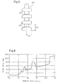
- an acoustic resonance test was performed by use of each of these insulator apparatuses (Experiment 2).
- Sample insulators Insulators of the following three kinds were employed as sample insulators to be tested. Comparative Example 1: an insulator having the same structure as that of the insulator 10 shown in FIG. 1 and configured such that the shed diameter is 300 mm; and the length of the outermost, first rib portion 13a is 40 mm. Comparative Example 2: an insulator having the same structure as that of the insulator shown in FIG. 1 of Japanese Patent Publication ( kokoku ) No.
- Example 1 an insulator having the same structure as that of the insulator 20 shown in FIG.
- the shed diameter is 300 mm; the length of the outermost, first rib portion 23a is 40 mm; the third rib portion 23c has a length such that the third rib portion 23c intersects the straight line L1 tangent to the end of the first rib portion 23a and to that of the second rib portion 23b; and the fourth rib portion 23d has a length such that the fourth rib portion 23d intersects the straight line L2 tangent to the end of the first rib portion 23a and to that of the third rib portion 23c.
- Wind tunnel test The wind tunnel test employed the wind tunnel test chamber shown in FIG. 2 of Japanese Patent Publication ( kokoku ) No. 06-101261 (the applicant is the same as that of the present application). A plurality of sample insulators were connected in series . The resultant string of insulators was hung from the ceiling of the wind tunnel test chamber. Wind was directed laterally on the string of insulators at a wind velocity ranging from 0 m/sec to 25 m/sec. The sound pressure level was measured by use of a directional microphone installed with a predetermined distance from the string of insulators. The results are shown by the graph of FIG. 6 (Comparative Example 1), the graph of FIG. 7 (Comparative Example 2), and the graph of FIG. 8 (Example 1).
- Sample insulator apparatus Insulator apparatus of the following three kinds were employed as sample insulator apparatus to be tested, while a number of different values of D/H ratio were employed. Insulator apparatus having the same structure as that of the insulator apparatus 30A shown in FIG. 3 and consisting of insulators each having the same structure as that of the insulator 10 shown in FIG. 1 and having a shed diameter of 300 mm and a length of the outermost, first rib portion 13a of 40 mm; insulator apparatus having the same structure as that of the insulator apparatus 30B shown in FIG. 4 and consisting of insulators having the same structure and dimensions as described above; and insulator apparatus having the same structure as that of the insulator apparatus 30C shown in FIG.
- insulator apparatus having a D/H ratio not greater than 0.7 exhibit a distinguished level not greater than 3 dB, implying that an insulator apparatus having a D/H ratio not greater than 0.7 is free from acoustic resonance.
- insulator apparatus having a D/H ratio not less than 0.8 Comparative Example 3, which corresponds to the insulator apparatus shown in FIG.
Landscapes
- Insulators (AREA)
Abstract
Description
- The present invention relates to an insulator and to an insulator apparatus comprising a plurality of insulators connected vertically in series.
- A certain type of insulator has a disklike shed portion and a plurality of annular rib portions concentrically formed on the underside of the shed portion and projecting downward along respectively predetermined lengths; and a certain type of insulator apparatus is configured such that a plurality of the insulators are connected vertically in series. An insulator and an insulator apparatus are adapted to hang a transmission line or the like on a steel tower or an electric pole. In order to cope with recent tendency toward super-high transmission voltage, the size of an insulator itself is increased, or the number of insulators to be connected is increased so as to increase the size of an insulator apparatus.
- At the site of installation, the above-mentioned insulator and insulator apparatus are exposed to wind, and may generate a loud noise at a certain wind velocity or wind direction. As the size of an insulator or insulator apparatus increases, the insulator or insulator apparatus generates noise at more times and at higher noise level.
- Particularly, frequent generation of a loud noise at night bothers local residents, and thus various noise control measures have been proposed and employed. Noise control measures in relation to an insulator are proposed in Japanese Patent Publication (kokoku) No. 06-101261 (first publication) and Japanese Patent Application Laid-Open (kokai) No. 05-67407 (second publication). Noise control measures in relation to an insulator apparatus are proposed in Japanese Patent Application Laid-Open (kokai) Nos. 2000-149686 (third publication) and 2000-311531 (fourth publication).
- The first and second publications describe a noise control measure applied to an insulator itself; specifically, the publications specify the shape of rib portions formed concentrically on the underside of a disklike shed portion. According to the first publication, the outermost rib portion and the next inner rib portion are configured such that a straight line tangent to the ends of the rib portions forms an angle of at least 35 degrees with respect to the horizontal direction. According to the second publication, the end portion of the outermost rib portion is formed into a wavy shape consisting of crests and troughs.
- The third and fourth publications describe a noise control measure applied to an insulator apparatus having a plurality of insulators connected vertically in series. According to the third publication, a string of insulators consists of heterogeneous insulators of different natural frequencies. According to the fourth publication, a string of insulators is configured such that insulators are arranged at different intervals each other.
- These insulators and insulator apparatus each have a noise control mechanism. These noise control mechanisms are based on the technical idea of "wind noise generation mechanism of insulator," and do not necessarily provide sufficient control over noise. According to the conventional "wind noise generation mechanism of insulator, " wind causes generation of a Karman vortex between rib portions of an insulator; the thus-generated Karman vortex induces micro-vibration of the rib portions; and the frequency of micro-vibration coincides with the natural frequency of a shed portion of the insulator to thereby generate wind noise.
- The inventors of the present invention carried out extensive studies and found the following: in an insulator having a disklike shed portion and a plurality of annular rib portions concentrically formed on the underside of the shed portion and projecting downward along respectively predetermined lengths, when non-turbulent wind blows along a straight line tangent to the end of the first rib portion located outermost and to that of the second rib portion located inside and adjacent to the first rib portion, a Karman vortex is generated between rib portions, and ribs repeatedly undergo micro-vibration, thereby generating a slight noise; the frequency of micro-vibration induced by a Karman vortex is determined by wind velocity and an interval between rib portions; when wind blows continuously at a certain velocity, the frequency of micro-vibration induced by a Karman vortex coincides with the acoustic natural frequency of a space provided between adjacent insulators of an insulator apparatus; and these phenomena generate resonance, thus leading to generation of a loud noise.
- An object of the present invention is to implement, on the basis of the above-mentioned findings , noise control measures applied to the above-described insulator and the above-described insulator apparatus.
- The present invention is directed to an insulator and to an insulator apparatus, and is more particularly applied to an insulator having a disklike shed portion and a plurality of annular rib portions concentrically formed on the underside of the shed portion and projecting downward along respectively predetermined lengths, and to an insulator apparatus configured such that a plurality of the insulators are connected vertically in series.
- An insulator according to the present invention is the above-described insulator characterized in that among the rib portions, a first rib portion located outermost is the longest; a second rib portion located inside and adjacent to the first rib portion is shorter than the first rib portion; a third rib portion located inside and adjacent to the second rib portion assumes a length such that the third rib portion intersects a straight line tangent to the end of the first rib portion and to that of the second rib portion; and a fourth rib portion located inside and adjacent to the third rib portion assumes a length such that the fourth rib portion intersects a straight line tangent to the end of the first rib portion and to that of the third rib portion.
- An insulator apparatus according to the present invention is the above-described insulator apparatus characterized in that a D/H ratio is not greater than 0.7, where D is a radius of the shed portion of each of the insulators, and H is a distance between lower ends of adjacent insulators.
- In the insulator according to the present invention, when non-turbulent wind blows along a straight line tangent to the end of the first rib portion located outermost and to that of the second rib portion located inside and adjacent to the first rib portion, the wind impinges against an end part of the third rib portion and is reflected, and the reflected wind disturbs air flow present between the first rib portion and the second rib portion, which air flow would otherwise allow generation of a Karman vortex. Thus, there can be prevented generation of a Karman vortex between the first rib portion and the second rib portion.
- When non-turbulent wind blows along a straight line tangent to the end of the first rib portion and to that of the third rib portion, the wind impinges against an end part of the fourth rib portion and is reflected, and the reflected wind disturbs air flow present between the first rib portion and the third rib portion, which air flow would otherwise allow generation of a Karman vortex. Thus, there can be prevented generation of a Karman vortex between the first rib portion and the third rib portion.
- Therefore, the insulator according to the present invention is completely or substantially free from generation of micro-vibration to be induced by a Karman vortex generated between rib portions; in other words, the insulator can control generation of a Karman vortex, which is a factor to induce noise, thereby preventing generation of noise from the same and from an insulator apparatus.
- In the case of an insulator having a fifth rib portion and a rib portion located inside the fifth rib portion, since these rib portions are located a considerable distance from the outermost, first rib portion, and the diameters of the rib portions are small, a Karman vortex is seldom generated between the first rib portion and either of these rib portions, or, when generated, such a Karman vortex is of low magnitude. Therefore, no particular preventive means is required for preventing generation of a Karman vortex between the first rib portion and either of these rib portions.
- An insulator apparatus to which the present invention is to be applied usually assumes a D/H ratio of 0.8-1.3, where D is the radius of the shed portion of each of insulators, and H is the distance between the lower ends of adjacent insulators. As a result, such an insulator apparatus often exhibits a phenomenon such that, in a string of insulators, the acoustic natural frequency of a space provided between adjacent insulators coincides with the frequency of micro-vibration induced by a Karman vortex generated between rib portions of each insulator.
- By contrast, the insulator apparatus according to the present invention assumes a D/H ratio not greater than 0.7, thereby avoiding the coincidence between the acoustic natural frequency of a space provided between adjacent insulators and the frequency of micro-vibration induced by a Karman vortex generated between rib portions of each insulator.
- Therefore, in the case of the insulator apparatus according to the present invention, even when a Karman vortex is generated between rib portions with resultant generation of micro-vibration, there can be prevented generation of a loud noise, which would otherwise result from the coincidence between the frequency of micro-vibration and the acoustic natural frequency of a space provided between adjacent insulators.
-
- FIG. 1 is a partially sectional side view of a conventional insulator to which the present invention is applied;
- FIG. 2 is a partially sectional side view of an insulator according to an embodiment of the present invention;
- FIG. 3 is a side view of a conventional insulator apparatus to which the present invention is applied;
- FIG. 4 is a side view of an insulator apparatus according to an embodiment of the present invention;
- FIG. 5 is a side view of an insulator apparatus according to another embodiment of the present invention;
- FIG. 6 is a graph showing the relationship between wind velocity and noise level obtained from an wind tunnel test on a conventional insulator;
- FIG. 7 is a graph showing the relationship between wind velocity and noise level obtained from an wind tunnel test on another conventional insulator;
- FIG. 8 is a graph showing the relationship between wind velocity and noise level obtained from an wind tunnel test on an insulator according to the present invention;
- FIG. 9 is a schematic view showing the method of an acoustic resonance test; and
- FIG. 10 is a graph showing the relationship between D/H ratio and distinguished level obtained from an acoustic resonance test on insulator apparatus.
-
- A noise-controlled insulator according to a first aspect of the present invention is applicable to an insulator having a disklike shed portion and a plurality of annular rib portions formed concentrically on the underside of the shed portion and projecting downward along respectively predetermined lengths. FIG. 1 shows a conventional,
typical insulator 10 of the above-described type, and FIG. 2 shows aninsulator 20 according to an embodiment of the present invention. Theinsulator insulator body metallic cap metallic pin - The
insulator body disklike shed portion 11 or 21; anannular connection portion shed portion 11 or 12 toward the front side of theshed portion 11 or 12; and a plurality of rib portions 13a-13e or 23a-23e formed concentrically on the backside of theshed portion 11 or 21. - Assuming a substantially annular form, the
metallic cap engagement recess 14a or 24a formed at a central part of the same and opening downward, and a connection recess 14b or 24b formed at a crest part of the same. Themetallic cap connection portion shed portion 11 or 21 of theinsulator body connection portion cement - The
metallic pin columnar body diameter attachment portion 16b or 26b formed at the upper end of thecolumnar body diameter attachment portion columnar body metallic pin attachment portion 16b or 26b into acavity connection portion shed portion 11 or 21 of theinsulator body connection portion cement - The
metallic pin attachment portion recess metallic cap recess metallic cap metallic pins insulator bodies - The
insulator body insulator shed portion 11 or 21 along respectively predetermined lengths. - In the
conventional insulator 10, the rib portions 13a-13e of theinsulator body 10a are arranged in the following manner: the outermost rib portion 13a (first rib portion), therib portion 13b (second rib portion), therib portion 13c (third rib portion), therib portion 13d (fourth rib portion), and therib portion 13e (fifth rib portion) are arranged sequentially inward in the descending order of length. - By contrast, in the
insulator 20 according to an embodiment of the present invention, therib portions 23a-23e of theinsulator body 20a are arranged in the following manner: theoutermost rib portion 23a (first rib portion) is the longest; theinnermost rib portion 23e (fifth rib portion) is the shortest; theintermediate rib portions 23b (second rib portion), 23c (third rib portion), and 23d (fourth rib portion) located between therib portions rib portions 23a-23e. - In the
insulator body 20a of theinsulator 20, therib portions 23a-23e assume the following length relationship: the outermost,first rib portion 23a located outermost is the longest ; thesecond rib portion 23b adjacent to thefirst rib portion 23a is shorter than thefirst rib portion 23a; and the innermost,fifth rib portion 23e is the shortest. Thethird rib portion 23c adjacent to thesecond rib portion 23b assumes a length such that thethird rib portion 23c intersects a straight line L1 tangent to the end of thefirst rib portion 23a and to that of thesecond rib portion 23b. Thefourth rib portion 23d adjacent to thethird rib portion 23c assumes a length such that thefourth rib portion 23d intersects a straight line L2 tangent to the end of thefirst rib portion 23a and to that of thethird rib portion 23c. FIG. 2 shows theinsulator 20 in which such length relationship is established among therib portions 23a-23e. - In an insulator in the above-described form; for example, the
conventional insulator 10 shown in FIG. 1, when non-turbulent wind blows along a straight line L3 tangent to the end of the outermost, first rib portion 13a and to that of thesecond rib portion 13b, the wind generates a Karman vortex between the first rib portion 13a and thesecond rib portion 13b, thereby inducing micro-vibration of theinsulator body 10a. When the frequency of this micro-vibration coincides with the acoustic natural frequency of a space provided between adjacent insulators of an insulator apparatus , the insulator apparatus generates a loud noise. - By contrast, in the
insulator 20 according to the present embodiment as shown in FIG. 2, when non-turbulent wind blows along the straight line L1 tangent to the end of the outermost,first rib portion 23a and to that of thesecond rib portion 23b, the wind impinges against an end part of thethird rib portion 23c and is reflected, and the reflected wind disturbs air flow present between thefirst rib portion 23a and thesecond rib portion 23b, which air flow would otherwise allow generation of a Karman vortex. Thus, there can be prevented generation of a Karman vortex between thefirst rib portion 23a and thesecond rib portion 23b. - When non-turbulent wind blows along the straight line L2 tangent to the end of the
first rib portion 23a and to that of thethird rib portion 23c, the wind impinges against an end part of thefourth rib portion 23d and is reflected, and the reflected wind disturbs air flow present between thefirst rib portion 23a and thethird rib portion 23c, which air flow would otherwise allow generation of a Karman vortex. Thus, there can be prevented generation of a Karman vortex between thefirst rib portion 23a and thethird rib portion 23c. - Therefore, the
insulator 20 is completely or substantially free from generation of micro-vibration to be induced by a Karman vortex generated betweenrib portions 23a-23e; in other words, theinsulator 20 can control generation of a Karman vortex, which is a factor to induce noise, thereby preventing generation of noise from the same and from an insulator apparatus. - In the
insulator 20, since thefifth rib portion 23e is located a considerable distance from the outermost,first rib portion 23a and the diameter of thefifth rib portion 23e is small, the chance of generation of a Karman vortex between therib portions rib portions - A noise-controlled insulator apparatus to a second aspect of the present invention is applicable to an insulator apparatus including a plurality of insulators connected vertically in series, the insulators each having a disklike shed portion and a plurality of annular rib portions formed concentrically on an underside of the shed portion and projecting downward along respectively predetermined lengths. FIG. 3 shows a conventional,
typical insulator apparatus 30A in this form; FIG. 4 shows aninsulator apparatus 30B according to an embodiment of the present invention; and FIG. 5 shows aninsulator apparatus 30C according to another embodiment of the present invention. Theseinsulator apparatus 30A-30C use, as components, insulators in the same form as that of theinsulator 10 shown in FIG. 1. - The
conventional insulator apparatus 30A shown in FIG. 3 is configured such that a plurality ofinsulators 30a are connected in series, eachinsulator 30a having the same structure as that of theinsulator 10 shown in FIG. 1, while a shed portion of eachinsulator 30a has a radius D0, and a distance H0 is maintained between the lower ends of theadjacent insulators 30a. Generally, theconventional insulator apparatus 30A has a ratio D0/H0 of 0.8-1.3. - By contrast, the
insulator apparatus 30B according to an embodiment of the present invention as shown in FIG. 4 is configured such that a plurality ofinsulators 30b are connected in series, eachinsulator 30b having the same structure as that of theinsulator 10 shown in FIG. 1, while a shed portion of eachinsulator 30b has the radius D0, and a distance H1 is maintained between the lower ends of theadjacent insulators 30b. The distance H1 is greater than the distance H0 of theconventional insulator apparatus 30a, and is attained by using for theinsulator 30b a metallic pin longer than that of theinsulator 30a, whereby theinsulator apparatus 30B has a ratio D0/H1 not greater than 0.7. - The
insulator apparatus 30C according to another embodiment of the present invention as shown in FIG. 5 is configured such that a plurality ofinsulators 30c are connected in series, eachinsulator 30c having the same structure as that of theinsulator 10 shown in FIG. 1, while a shed portion of eachinsulator 30c has a radius D1, and the distance H0 is maintained between the lower ends of theadjacent insulators 30c. The radius D1 is less than the radius D0 of theconventional insulator apparatus 30a, whereby theinsulator apparatus 30C has a ratio D1/H0 not greater than 0.7. - The
conventional insulator apparatus 30A assumes a ratio D0/H0 of 0.8-1.3, where D0 is the radius of the shed portion of each of theinsulators 30a, and H0 is the distance between the lower ends ofadjacent insulators 30a. As a result, theinsulator apparatus 30A often exhibits a phenomenon such that, in a string ofinsulators 30a, the acoustic natural frequency of a space provided betweenadjacent insulators 30a coincides with the frequency of micro-vibration induced by a Karman vortex generated between rib portions of eachinsulator 30a. When the acoustic natural frequency coincides with the frequency of micro-vibration, theinsulator apparatus 30A generates a loud noise. - By contrast, the
insulator apparatus insulator adjacent insulators insulator apparatus adjacent insulators insulator insulator apparatus - An insulator (Comparative Example 1) having the same structure as that of the
insulator 10 shown in FIG. 1, an insulator (Comparative Example 2) having the same structure as that of the insulator shown in FIG. 1 of Japanese Patent Publication (kokoku) No. 06-101261, and an insulator (Example 1) having the same structure as that of theinsulator 20 shown in FIG. 2 were fabricated and subjected to a wind tunnel test (Experiment 1). - Moreover, by use of insulators having the same structure as that of the
insulator 10 shown in FIG. 1, an insulator apparatus (Comparative Example 3) having the same structure as that of theinsulator apparatus 30A shown in FIG . 3, an insulator apparatus (Example 2) having the same structure as that of theinsulator apparatus 30B shown in FIG. 4, and an insulator apparatus (Example 3) having the same structure as that of theinsulator apparatus 30C shown in FIG. 5 were fabricated. Subsequently, an acoustic resonance test was performed by use of each of these insulator apparatuses (Experiment 2). - Sample insulators : Insulators of the following three kinds were employed as sample insulators to be tested. Comparative Example 1: an insulator having the same structure as that of the
insulator 10 shown in FIG. 1 and configured such that the shed diameter is 300 mm; and the length of the outermost, first rib portion 13a is 40 mm. Comparative Example 2: an insulator having the same structure as that of the insulator shown in FIG. 1 of Japanese Patent Publication (kokoku) No. 06-101261 and configured such that the shed diameter is 300 mm; the length of the outermost, first rib portion is 40 mm; and the third rib portion has a length such that the third rib portion intersects a straight line tangent to the end of the first rib portion and to that of the second rib portion . Example 1: an insulator having the same structure as that of theinsulator 20 shown in FIG. 2 and configured such that the shed diameter is 300 mm; the length of the outermost,first rib portion 23a is 40 mm; thethird rib portion 23c has a length such that thethird rib portion 23c intersects the straight line L1 tangent to the end of thefirst rib portion 23a and to that of thesecond rib portion 23b; and thefourth rib portion 23d has a length such that thefourth rib portion 23d intersects the straight line L2 tangent to the end of thefirst rib portion 23a and to that of thethird rib portion 23c. - Wind tunnel test: The wind tunnel test employed the wind tunnel test chamber shown in FIG. 2 of Japanese Patent Publication (kokoku) No. 06-101261 (the applicant is the same as that of the present application). A plurality of sample insulators were connected in series . The resultant string of insulators was hung from the ceiling of the wind tunnel test chamber. Wind was directed laterally on the string of insulators at a wind velocity ranging from 0 m/sec to 25 m/sec. The sound pressure level was measured by use of a directional microphone installed with a predetermined distance from the string of insulators. The results are shown by the graph of FIG. 6 (Comparative Example 1), the graph of FIG. 7 (Comparative Example 2), and the graph of FIG. 8 (Example 1).
- Study on test results: According to the results of measurement of sound pressure level, all of the tested insulators show a gradual increase in sound pressure level with wind velocity; however, in the case of the insulators of Comparative Example 1, as is apparent from the graph of FIG. 6, a plurality of local sound pressure peaks appear over a wide wind velocity range of from low wind velocity to high wind velocity, implying generation of noise in a plurality of wind velocity zones.
- In the case of the insulators of Comparative Example 2, as is apparent from the graph of FIG. 7, no local sound pressure peaks appear over a wind velocity range of from low wind velocity to medium wind velocity; however, a sound pressure peak appears in a high wind velocity zone, implying generation of noise in a high wind velocity zone.
- By contrast, in the case of the insulators of Example 1, as is apparent from the graph of FIG. 8, no local sound pressure peaks appear in a wind velocity range of from 0 m/sec to 25 m/sec, implying that no noise is generated over the wind velocity range.
- Sample insulator apparatus: Insulator apparatus of the following three kinds were employed as sample insulator apparatus to be tested, while a number of different values of D/H ratio were employed. Insulator apparatus having the same structure as that of the
insulator apparatus 30A shown in FIG. 3 and consisting of insulators each having the same structure as that of theinsulator 10 shown in FIG. 1 and having a shed diameter of 300 mm and a length of the outermost, first rib portion 13a of 40 mm; insulator apparatus having the same structure as that of theinsulator apparatus 30B shown in FIG. 4 and consisting of insulators having the same structure and dimensions as described above; and insulator apparatus having the same structure as that of theinsulator apparatus 30C shown in FIG. 5 consisting of insulators having the same structure and dimensions as described above. Various values of D/H ratio ranging from 0.44 to 1.41 were employed through employment of various values of the radius D of a shed portion ranging from 57 mm to 196 mm and various values of the distance H between the lower ends of adjacent insulators ranging from 100 mm to 320 mm. Dimensional features and D/H values of the sample insulator apparatus are shown in Table. - Acoustic resonance test: An each sample insulator apparatus was hung in the acoustic test chamber as shown in FIG. 9; a speaker 42 was installed so as to face a space provided between adjacent insulators of a string of
insulators 41; sound of the same frequency as the acoustic natural frequency of the space was produced from the speaker 42 so as to acoustically vibrate the insulators; the resultant sound volume was measured by use of a microphone 43; an acoustic resonance level in the space was determined from an acoustic distinguished level. The results are shown in Table and by the graph of FIG. 10.Sample insulator apparatus Radius of shed portion D (mm) Distance between lower ends H (mm) Ratio D/H Distinguished level (dBA) Distinguished ratio (times) 1 81 185 0.44 0 1.0 2 57 100 0.57 1 1.1 3 188 320 0.59 2 1.3 4 59 100 0.59 2 1.3 5 111 185 0.60 3 1.4 6 141 230 0.61 3 1.4 7 188 260 0.72 3 1.4 8 148 195 0.76 10 3.2 9 156 205 0.76 12 4.0 10 141 185 0.76 6 2.0 11 130 170 0.76 1.1 3.5 12 188 245 0.77 5 1.8 13 81 100 0.81 13 4.5 14 119 146 0.82 14 5.0 15 87 100 0.87 14 5.0 16 150 170 0.88 16 6.3 17 89 100 0.89 14 5.0 18 196 205 0.96 17 7.1 19 188 195 0.96 18 7.9 20 111 100 1.11 18 7.9 21 117 100 1.17 19 8.9 22 141 100 1.41 20 10.0 - Study on test results: The acoustic resonance test has revealed that insulator apparatus having a D/H ratio not greater than 0.7 (Examples 2 and 3, which correspond to the insulator apparatus shown in FIGS. 4 and 5) exhibit a distinguished level not greater than 3 dB, implying that an insulator apparatus having a D/H ratio not greater than 0.7 is free from acoustic resonance. By contrast, insulator apparatus having a D/H ratio not less than 0.8 (Comparative Example 3, which corresponds to the insulator apparatus shown in FIG. 3) exhibit a sharp increase in distinguished level at a D/H ratio in excess of 0.8, implying that an insulator apparatus having a D/H ratio not less than 0.8 generates noise as a result of acoustic resonance. The wind tunnel test (at a wind velocity of 0-25 m/sec) was also carried out on these insulator apparatus. The results obtained from the wind tunnel test exhibit a tendency similar to that obtained from the acoustic resonance test.
Claims (6)
- An insulator comprising a disklike shed portion (21) and a plurality of annular rib portions (23a to 23e) formed concentrically on an underside of the shed portion (21) and projecting downward along respectively predetermined lengths, characterized in that among the rib portions (23a to 23e), a first rib portion (23a) located outermost is the longest; a second rib portion (23b) located inside and adjacent to the first rib portion (23a) is shorter than the first rib portion (23a); a third rib portion (23c) located inside and adjacent to the second rib portion (23b) assumes a length such that the third rib portion (23c) intersects a straight line tangent to an end of the first rib portion (23a) and to an end of the second rib portion (23b); and a fourth rib portion (23d) located inside and adjacent to the third rib portion (23c) assumes a length such that the fourth rib portion (23d) intersects a straight line tangent to the end of the first rib portion (23a) and to the end of the third rib portion (23c).
- An insulator as described in claim 1, characterized in that the second rib portion (23b) and the third rib portion (23c) extend downward along substantially the same length.
- An insulator as described in claim 2, characterized in that the fourth rib portion (23d) extends downward along a length substantially equal to that along which the second rib portion (23b) and the third rib portion (23c) extend downward.
- An insulator as described in claim 1, characterized by further comprising a fifth rib portion (23e) located inside and adjacent to the fourth rib portion (23d).
- An insulator as described in claim 4, characterized in that, among the rib portions (23a to 23e), the fifth rib portion (23e) extends downward along the shortest length.
- An insulator apparatus comprising a plurality of insulators (20) connected vertically in series, the insulators (20) each comprising a disklike shed portion (21) and a plurality of annular rib portions (23a to 23e) formed concentrically on an underside of the shed portion (21) and projecting downward along respectively predetermined lengths, characterized in that a D/H ratio is not greater than 0.7, where D is a radius of the shed portion (21) of each of the insulators (20), and H is a distance between lower ends of adjacent insulators (20).
Applications Claiming Priority (2)
| Application Number | Priority Date | Filing Date | Title |
|---|---|---|---|
| JP2001211944 | 2001-07-12 | ||
| JP2001211944A JP2003031062A (en) | 2001-07-12 | 2001-07-12 | Insulators and insulator devices |
Publications (3)
| Publication Number | Publication Date |
|---|---|
| EP1276118A2 true EP1276118A2 (en) | 2003-01-15 |
| EP1276118A3 EP1276118A3 (en) | 2003-11-19 |
| EP1276118B1 EP1276118B1 (en) | 2008-12-31 |
Family
ID=19047182
Family Applications (1)
| Application Number | Title | Priority Date | Filing Date |
|---|---|---|---|
| EP20020254811 Expired - Lifetime EP1276118B1 (en) | 2001-07-12 | 2002-07-09 | Insulator and insulator apparatus |
Country Status (3)
| Country | Link |
|---|---|
| EP (1) | EP1276118B1 (en) |
| JP (1) | JP2003031062A (en) |
| DE (1) | DE60230565D1 (en) |
Cited By (1)
| Publication number | Priority date | Publication date | Assignee | Title |
|---|---|---|---|---|
| CN103456428A (en) * | 2013-01-09 | 2013-12-18 | 河北荣森电气有限公司 | Pressing connection immersion bell-shaped disc-shaped suspension type composite insulator chain element |
Families Citing this family (4)
| Publication number | Priority date | Publication date | Assignee | Title |
|---|---|---|---|---|
| JP2008262762A (en) * | 2007-04-11 | 2008-10-30 | Chugoku Electric Power Co Inc:The | Insulator set |
| CN101877258B (en) * | 2009-04-30 | 2012-05-30 | 呼和浩特市硅谷电力设备有限公司 | Disc type suspension double-insulation composite insulator |
| JP5537229B2 (en) * | 2010-03-31 | 2014-07-02 | 日本碍子株式会社 | Wind noise prevention |
| JP6208454B2 (en) * | 2013-04-01 | 2017-10-04 | 日本車輌製造株式会社 | Railway vehicle current collector |
Citations (2)
| Publication number | Priority date | Publication date | Assignee | Title |
|---|---|---|---|---|
| US4140871A (en) | 1976-09-28 | 1979-02-20 | Ngk Insulators Ltd. | Suspension insulators |
| GB2225176A (en) | 1988-11-18 | 1990-05-23 | Sp Kt Bjuro Izolyatoram I Arma | High-voltage suspension insulator |
-
2001
- 2001-07-12 JP JP2001211944A patent/JP2003031062A/en active Pending
-
2002
- 2002-07-09 DE DE60230565T patent/DE60230565D1/en not_active Expired - Lifetime
- 2002-07-09 EP EP20020254811 patent/EP1276118B1/en not_active Expired - Lifetime
Patent Citations (2)
| Publication number | Priority date | Publication date | Assignee | Title |
|---|---|---|---|---|
| US4140871A (en) | 1976-09-28 | 1979-02-20 | Ngk Insulators Ltd. | Suspension insulators |
| GB2225176A (en) | 1988-11-18 | 1990-05-23 | Sp Kt Bjuro Izolyatoram I Arma | High-voltage suspension insulator |
Cited By (1)
| Publication number | Priority date | Publication date | Assignee | Title |
|---|---|---|---|---|
| CN103456428A (en) * | 2013-01-09 | 2013-12-18 | 河北荣森电气有限公司 | Pressing connection immersion bell-shaped disc-shaped suspension type composite insulator chain element |
Also Published As
| Publication number | Publication date |
|---|---|
| DE60230565D1 (en) | 2009-02-12 |
| EP1276118B1 (en) | 2008-12-31 |
| JP2003031062A (en) | 2003-01-31 |
| EP1276118A3 (en) | 2003-11-19 |
Similar Documents
| Publication | Publication Date | Title |
|---|---|---|
| EP1775560B1 (en) | Ultrasonic flow meter with flow mixer | |
| EP1276118B1 (en) | Insulator and insulator apparatus | |
| KR19990044919A (en) | A waveguide that extends radially and has multiple flat surfaces | |
| US6722196B2 (en) | Device for measuring at least one parameter of a flowing medium | |
| JPH0885921A (en) | Noise barrier | |
| US6648278B1 (en) | Offset hanger | |
| KR19990072356A (en) | Sound arrester | |
| CN103985378B (en) | Silencer | |
| JP3564779B2 (en) | Resonant sound generation prevention device for cavity | |
| US4686928A (en) | Toroidal whistle | |
| JPH02153212A (en) | Silencer | |
| JPH1113164A (en) | Resonator type sound absorbing panel | |
| SE513424C2 (en) | Noise suppression device. | |
| JPH09198052A (en) | Sound absorbing board material | |
| CN216560412U (en) | Reverberation chamber with curved walls | |
| JPH06101261B2 (en) | Noise prevention insulator | |
| Pyshin et al. | Acoustical properties of escalator tunnels in St.-Petersburg underground | |
| ITMI20020449U1 (en) | PLANE CABLE | |
| JP2009030364A (en) | Vertical latticed handrail | |
| YU17398A (en) | Lamelar violine 4/4 | |
| KR100274936B1 (en) | Muffler for compressor | |
| JP2613013B2 (en) | Sound absorbing material | |
| JP2005139611A (en) | Soundproof device | |
| DE3807299A1 (en) | Electronic organ | |
| JPH09264009A (en) | Noise barrier |
Legal Events
| Date | Code | Title | Description |
|---|---|---|---|
| PUAI | Public reference made under article 153(3) epc to a published international application that has entered the european phase |
Free format text: ORIGINAL CODE: 0009012 |
|
| AK | Designated contracting states |
Kind code of ref document: A2 Designated state(s): AT BE BG CH CY CZ DE DK EE ES FI FR GB GR IE IT LI LU MC NL PT SE SK TR |
|
| AX | Request for extension of the european patent |
Free format text: AL;LT;LV;MK;RO;SI |
|
| PUAL | Search report despatched |
Free format text: ORIGINAL CODE: 0009013 |
|
| AK | Designated contracting states |
Kind code of ref document: A3 Designated state(s): AT BE BG CH CY CZ DE DK EE ES FI FR GB GR IE IT LI LU MC NL PT SE SK TR |
|
| AX | Request for extension of the european patent |
Extension state: AL LT LV MK RO SI |
|
| 17P | Request for examination filed |
Effective date: 20031212 |
|
| AKX | Designation fees paid |
Designated state(s): DE GB |
|
| 17Q | First examination report despatched |
Effective date: 20080205 |
|
| GRAP | Despatch of communication of intention to grant a patent |
Free format text: ORIGINAL CODE: EPIDOSNIGR1 |
|
| GRAS | Grant fee paid |
Free format text: ORIGINAL CODE: EPIDOSNIGR3 |
|
| GRAA | (expected) grant |
Free format text: ORIGINAL CODE: 0009210 |
|
| AK | Designated contracting states |
Kind code of ref document: B1 Designated state(s): DE GB |
|
| REG | Reference to a national code |
Ref country code: GB Ref legal event code: FG4D |
|
| REF | Corresponds to: |
Ref document number: 60230565 Country of ref document: DE Date of ref document: 20090212 Kind code of ref document: P |
|
| PLBE | No opposition filed within time limit |
Free format text: ORIGINAL CODE: 0009261 |
|
| STAA | Information on the status of an ep patent application or granted ep patent |
Free format text: STATUS: NO OPPOSITION FILED WITHIN TIME LIMIT |
|
| 26N | No opposition filed |
Effective date: 20091001 |
|
| PGFP | Annual fee paid to national office [announced via postgrant information from national office to epo] |
Ref country code: DE Payment date: 20140702 Year of fee payment: 13 |
|
| PGFP | Annual fee paid to national office [announced via postgrant information from national office to epo] |
Ref country code: GB Payment date: 20140709 Year of fee payment: 13 |
|
| REG | Reference to a national code |
Ref country code: DE Ref legal event code: R119 Ref document number: 60230565 Country of ref document: DE |
|
| GBPC | Gb: european patent ceased through non-payment of renewal fee |
Effective date: 20150709 |
|
| PG25 | Lapsed in a contracting state [announced via postgrant information from national office to epo] |
Ref country code: DE Free format text: LAPSE BECAUSE OF NON-PAYMENT OF DUE FEES Effective date: 20160202 Ref country code: GB Free format text: LAPSE BECAUSE OF NON-PAYMENT OF DUE FEES Effective date: 20150709 |