EP1276103A2 - Optical pickup with vibration suppression of lens holder - Google Patents
Optical pickup with vibration suppression of lens holder Download PDFInfo
- Publication number
- EP1276103A2 EP1276103A2 EP02254920A EP02254920A EP1276103A2 EP 1276103 A2 EP1276103 A2 EP 1276103A2 EP 02254920 A EP02254920 A EP 02254920A EP 02254920 A EP02254920 A EP 02254920A EP 1276103 A2 EP1276103 A2 EP 1276103A2
- Authority
- EP
- European Patent Office
- Prior art keywords
- tracking
- focusing
- coil
- lens holder
- optical pickup
- Prior art date
- Legal status (The legal status is an assumption and is not a legal conclusion. Google has not performed a legal analysis and makes no representation as to the accuracy of the status listed.)
- Withdrawn
Links
Images

Classifications
-
- G—PHYSICS
- G11—INFORMATION STORAGE
- G11B—INFORMATION STORAGE BASED ON RELATIVE MOVEMENT BETWEEN RECORD CARRIER AND TRANSDUCER
- G11B7/00—Recording or reproducing by optical means, e.g. recording using a thermal beam of optical radiation by modifying optical properties or the physical structure, reproducing using an optical beam at lower power by sensing optical properties; Record carriers therefor
- G11B7/08—Disposition or mounting of heads or light sources relatively to record carriers
- G11B7/09—Disposition or mounting of heads or light sources relatively to record carriers with provision for moving the light beam or focus plane for the purpose of maintaining alignment of the light beam relative to the record carrier during transducing operation, e.g. to compensate for surface irregularities of the latter or for track following
- G11B7/0925—Electromechanical actuators for lens positioning
- G11B7/0932—Details of sprung supports
-
- G—PHYSICS
- G11—INFORMATION STORAGE
- G11B—INFORMATION STORAGE BASED ON RELATIVE MOVEMENT BETWEEN RECORD CARRIER AND TRANSDUCER
- G11B7/00—Recording or reproducing by optical means, e.g. recording using a thermal beam of optical radiation by modifying optical properties or the physical structure, reproducing using an optical beam at lower power by sensing optical properties; Record carriers therefor
- G11B7/08—Disposition or mounting of heads or light sources relatively to record carriers
- G11B7/09—Disposition or mounting of heads or light sources relatively to record carriers with provision for moving the light beam or focus plane for the purpose of maintaining alignment of the light beam relative to the record carrier during transducing operation, e.g. to compensate for surface irregularities of the latter or for track following
- G11B7/0925—Electromechanical actuators for lens positioning
- G11B7/0933—Details of stationary parts
-
- G—PHYSICS
- G11—INFORMATION STORAGE
- G11B—INFORMATION STORAGE BASED ON RELATIVE MOVEMENT BETWEEN RECORD CARRIER AND TRANSDUCER
- G11B7/00—Recording or reproducing by optical means, e.g. recording using a thermal beam of optical radiation by modifying optical properties or the physical structure, reproducing using an optical beam at lower power by sensing optical properties; Record carriers therefor
- G11B7/08—Disposition or mounting of heads or light sources relatively to record carriers
- G11B7/09—Disposition or mounting of heads or light sources relatively to record carriers with provision for moving the light beam or focus plane for the purpose of maintaining alignment of the light beam relative to the record carrier during transducing operation, e.g. to compensate for surface irregularities of the latter or for track following
- G11B7/0925—Electromechanical actuators for lens positioning
- G11B7/0935—Details of the moving parts
Definitions
- This invention relates to an optical pickup for use in an optical disc drive for recording/reproducing data to/from an optical recording medium such as an optical disc.
- optical discs have been known.
- an audio CD CD-DA: Compact Disc-Digital Audio
- a CD-ROM Compact Disc-Read Only Memory
- a CD-R Compact Disc-Recordable
- a CD-RW Compact Disc-ReWritable
- DVD-Audio Digital Versatile Disc-Audio
- a DVD-Video Digital Versatile Disc-Video
- a DVD-ROM Digital Versatile Disc-Read Only Memory
- SACD Super Audio Compact Disc
- DVD-ROM Digital Versatile Disc-Read Only Memory
- a DVD-R Digital Versatile Disc-Recordable
- DVD+R Digital Versatile Disc+Recordable
- a DVD-RAM Digital Versatile Disc-Random Access Memory
- DVD-RW Digital Versatile Disc-ReWritable
- DVD+RW Digital Versatile Disc+ReWritable
- an optical pickup of the type comprises a laser source for generating a laser beam and an optical system for leading the laser beam generated by the laser source to the optical disc.
- the optical disc such as the CD-R
- the power level of the laser beam emitted from the laser source is changed between the data reading operation and the data writing operation.
- the laser beam emitted from the laser source is led through the optical system, i.e., through a diffraction grating, a beam splitter, a collimating lens, and an object lens to be irradiated to a surface of the optical disc.
- the laser beam is reflected by the optical disk and is led through the optical system, i.e., through the object lens, the collimating lens, and the beam splitter to be received by a PD (Photo Diode) as a light receiving device.
- a PD Photo Diode
- Such electronic apparatuses include not only an exclusive DVD-video player but also a personal computer, a TV (TeleVision set)-game apparatus, and so on.
- Each of those electric apparatuses has an optical pickup adapted to the DVD. Because the DVD has a higher recording density as compared with other optical discs such as the CD, the optical pickup adapted to the DVD is required to operate with higher precision than an existing optical pickup for the CD.
- the optical pickup has a lens holder with an object lens mounted thereon, a damper base supporting the lens holder through four suspension wires in a manner such that the lens holder is movable, and a yoke supporting the damper base.
- the yoke is provided with a pair of permanent magnets.
- the permanent magnets serve as a first element of a magnet-coil structure for moving the lens holder in tracking and focusing directions and by the use of magnetic force.
- the lens holder is provided with a focusing coil and a tracking coil.
- a combination of the focusing coil and the tracking coil serves as a second element of the above-mentioned magnet-coil structure and, cooperating with the permanent magnets, moves the lens holder in the tracking and the focusing directions by the use of the magnetic force.
- vibration suppression of the lens holder is insufficient, and unnecessary or undesired vibration called pitching and rolling may occur.
- the cause of such undesired vibration will be described.
- the focusing coil and the tracking coil produce driving forces having acting points different in location from each other. Therefore, an unnecessary moment is produced and acts on the lens holder to tilt the object lens. As a consequence, optical characteristics of the optical pickup are spoiled or degraded.
- the above-mentioned disadvantage is a serious problem particularly for the optical pickup adapted to the DVD because such optical pickup must operate with higher precision as compared with the optical pickup for the CD, as described above.
- an optical pickup which is for use in an optical disc drive for recording/reproducing data to/from an optical recording medium and which comprises a lens holder movably supported by suspension wires, an object lens attached to the lens holder, and focusing and tracking coils attached to the lens holder for electromagnetically driving the lens holder in focusing and tracking directions, respectively, in cooperation with a permanent magnet.
- the focusing and the tracking coils produce magnetic driving forces having acting points coincident in location with each other.
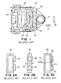
- the optical pickup has a lens holder 30 with an object lens 31 mounted thereon, a damper base 40 supporting the lens holder 30 through four suspension wires (only two of them being illustrated in the figure) in the manner such that the lens holder 30 is movable, and a yoke (not shown) supporting the damper base 40.
- the yoke is provided with a pair of permanent magnets 52 and 53.
- the permanent magnets 52 and 53 serve as a first element of a magnet-coil structure for moving the lens holder 30 in tracking and focusing directions TR and FC by the use of magnetic force.
- the lens holder 30 is provided with a focusing coil 32 and a pair of tracking coils 33.
- a combination of the focusing coil 32 and the tracking coils 33 serves as a second element of the above-mentioned magnet-coil structure and, cooperating with the permanent magnets 52 and 53, moves the lens holder 30 in the tracking and the focusing directions TR and FC by the use of the magnetic force.
- vibration suppression of the lens holder 30 is insufficient and unnecessary or undesired vibration called pitching and rolling may occur.
- the focusing coil 32 and the tracking coils 33 produce driving forces f FC and f TR having acting points different in location from each other (as best shown in Fig. 2C). Therefore, an unnecessary moment is produced and acts on the lens holder 30 to tilt the object lens 31. As a consequence, optical characteristics of the optical pickup are spoiled or degraded.
- a disc drive to which an optical pickup according to the embodiment is applicable is used in a DVD player known in the art.
- an optical pickup has, like the existing optical pickup shown in Fig. 1, a lens holder 10 with an object lens 31 mounted thereon, a damper base 40 supporting the lens holder 30 through four suspension wires (only two of them being illustrated in the figure) in the manner such that the lens holder 10 is movable, and a yoke (not shown) supporting the damper base 40.
- the yoke is provided with a pair of permanent magnets 52 and 53.
- the permanent magnets 52 and 53 serve as a first element of a magnet-coil structure for moving the lens holder 30 in tracking and focusing directions TR and FC by the use of magnetic force as driving forces.
- the lens holder 30 is provided with a focusing coil 12 and a pair of tracking coils which will later be described in detail.
- a combination of the focusing coil 12 and the tracking coils serve as a second element of the above-mentioned magnet-coil structure and, cooperating with the permanent magnets 52 and 53, moves the lens holder 30 in the tracking and the focusing directions TR and FC by the use of the magnetic force.
- the focusing coil 12 has a rectangular cylindrical shape which has four side portions.
- Each of the tracking coils comprises a pair of tracking coil portions 13 and 14.
- the tracking coil portions 13 and 14 are arranged outside and inside of one of the side portions of the focusing coil 12, respectively, with the one side portion interposed therebetween.
- the tracking coil portions 13 and 14 are equal in number of turns to each other and therefore have electromagnetic efficiencies equal to each other.
- the focusing coil 12 and the tracking coils each of which is composed of the tracking coil portions 13 and 14, produce driving forces f FC and f TR having acting points coincident in location with each other, as best shown in Fig. 4C.
- the driving force f FC by the focusing coil 12 and the driving force f TR by the tracking coil portions 13 and 14 act upon the same location in the focusing coil 12 attached on the lens holder 10. Consequently, any unnecessary moment never acts on the lens holder 10 so that vibration suppression of the lens holder 10 is excellent.
- the optical pickup is advantageous for use as the optical pickup adapted to the DVD, which is required to operate with higher precision as compared with the optical pickup for the CD.
- each of the focusing coil 12 and the tracking coil portions 13 and 14 is a hollow coreless type.
- at least one of these coils may be wound around a bobbin.
- An optical pickup includes a lens holder, an object lens, and focusing and tracking coils for electromagnetically driving the lens holder in focusing and tracking directions, respectively.
- the focusing and the tracking coils produce driving forces having acting points coincident in location with each other.
Landscapes
- Optical Recording Or Reproduction (AREA)
Abstract
Description
Claims (10)
- An optical pickup for use in an optical disc drive for recording/reproducing data to/from an optical recording medium, said optical pickup comprising a lens holder (10) movably supported by suspension wires, an object lens (31) attached to said lens holder, and focusing coil means and tracking coil means (12, 13, 14) attached to said lens holder for electro-magnetically driving said lens holder in a focusing direction (FC) and a tracking direction (TR), respectively, in cooperation with respective magnet means, characterized in that said focusing coil means and said tracking coil means produce driving forces (fFC, fTR) acting through a common point.
- The optical pickup as claimed in claim 1, wherein the focusing coil means comprises a single focusing coil, and the tracking coil means comprises a pair of tracking coils.
- The optical pickup as claimed in claim 2, wherein the pair of tracking coils is connected to the focusing coil.
- The optical pickup as claimed in claim 2 or 3, wherein:said focusing coil has a rectangular cylindrical shape which has four side portions; and,each tracking coil comprises a pair of tracking coil portions arranged outside and inside, respectively, of one of said side portions of said focusing coil, said one side portion of said focusing coil being interposed between said pair of tracking coil portions.
- The optical pickup as claimed in claim 4, wherein the pair of tracking coil portions have an equal number of turns to each other.
- An optical pickup as claimed in any one of claims 2 to 5, wherein at least one of said focusing and tracking coils is wound around a bobbin.
- A method for reducing vibration in an optical pickup for use in an optical disc drive for recording/reproducing data to/from an optical recording medium, said optical pickup comprising a lens holder (10) movably supported by suspension wires, an object lens (31) attached to said lens holder, and focusing coil means and tracking coil means (12, 13, 14) attached to said lens holder for electro-magnetically driving said lens holder in a focusing direction (FC) and a tracking direction (TR), respectively, in cooperation with respective magnet means, the method being characterized by the step of positioning said focusing coil means and tracking coil means on said lens holder such that said focusing coil means and said tracking coil means produce driving forces (fFC, fTR) acting through a common point.
- The method as claimed in claim 7, wherein the focusing coil means comprises a single focusing coil and the tracking coil means comprises a pair of tracking coils, and the positioning step includes the step of connecting the pair of tracking coils to the focusing coil.
- The method as claimed in claim 8, wherein each tracking coil comprises a pair of tracking coil portions, and wherein the positioning step includes the step of arranging each tracking coil on a side portion of the focusing coil such that the pair of tracking coil portions are respectively outside and inside of the side portion of the focusing coil.
- The method as claimed in claim 9, comprising the further step of arranging that the pair of tracking coil portions have an equal number of turns to each other.
Applications Claiming Priority (2)
| Application Number | Priority Date | Filing Date | Title |
|---|---|---|---|
| JP2001211587A JP2003030869A (en) | 2001-07-12 | 2001-07-12 | Optical pickup |
| JP2001211587 | 2001-07-12 |
Publications (2)
| Publication Number | Publication Date |
|---|---|
| EP1276103A2 true EP1276103A2 (en) | 2003-01-15 |
| EP1276103A3 EP1276103A3 (en) | 2004-09-29 |
Family
ID=19046870
Family Applications (1)
| Application Number | Title | Priority Date | Filing Date |
|---|---|---|---|
| EP02254920A Withdrawn EP1276103A3 (en) | 2001-07-12 | 2002-07-12 | Optical pickup with vibration suppression of lens holder |
Country Status (4)
| Country | Link |
|---|---|
| US (1) | US20030012119A1 (en) |
| EP (1) | EP1276103A3 (en) |
| JP (1) | JP2003030869A (en) |
| CN (1) | CN1407546A (en) |
Families Citing this family (2)
| Publication number | Priority date | Publication date | Assignee | Title |
|---|---|---|---|---|
| KR100513005B1 (en) * | 2003-07-04 | 2005-09-05 | 엘지전자 주식회사 | Opitcal pick-up actuator |
| JP4366404B2 (en) * | 2007-01-17 | 2009-11-18 | 株式会社日立メディアエレクトロニクス | Objective lens driving device and disk device using the same |
Family Cites Families (4)
| Publication number | Priority date | Publication date | Assignee | Title |
|---|---|---|---|---|
| US5136565A (en) * | 1988-12-20 | 1992-08-04 | Sanyo Electric Co., Ltd. | Optical device for reading and writing data on a recording medium |
| JP2728496B2 (en) * | 1989-04-21 | 1998-03-18 | 株式会社日立製作所 | Objective lens drive |
| US5808980A (en) * | 1991-02-15 | 1998-09-15 | Discovision Associates | Seek actuator for optical recording |
| US5724337A (en) * | 1993-10-29 | 1998-03-03 | Tdk Corporation | Optical pickup with a compact design |
-
2001
- 2001-07-12 JP JP2001211587A patent/JP2003030869A/en not_active Withdrawn
-
2002
- 2002-07-10 US US10/192,604 patent/US20030012119A1/en not_active Abandoned
- 2002-07-11 CN CN02141030.5A patent/CN1407546A/en active Pending
- 2002-07-12 EP EP02254920A patent/EP1276103A3/en not_active Withdrawn
Also Published As
| Publication number | Publication date |
|---|---|
| EP1276103A3 (en) | 2004-09-29 |
| CN1407546A (en) | 2003-04-02 |
| US20030012119A1 (en) | 2003-01-16 |
| JP2003030869A (en) | 2003-01-31 |
Similar Documents
| Publication | Publication Date | Title |
|---|---|---|
| KR100636127B1 (en) | Actuator for Optical Pickup | |
| JP2004103189A (en) | Optical pickup device and optical disk device | |
| KR20040042376A (en) | Magnetic circuit and actuator for optical pickup and optical recording and/or reproducing apparatus employing it | |
| CN100489973C (en) | Optical pickup device | |
| US20030012119A1 (en) | Optical pickup excellent in vibration suppression of lens holder | |
| JP2004185789A (en) | Lens actuator, optical pickup device and optical disk device | |
| US7668049B2 (en) | Optical pickup actuator and optical recording/reproducing apparatus | |
| EP1675112B1 (en) | Optical pickup actuator and optical recording and/or reproducing apparatus | |
| US7310289B2 (en) | Actuator for optical pickup of an optical disk drive and a method of using the same | |
| US6304391B1 (en) | Object lens supporting unit capable of offsetting positional deviation of the lens caused by warp of suspension wire and method of assembling the unit | |
| US20050259527A1 (en) | Optical component triaxial actuator and recording/reproducing apparatus using the same | |
| US20050229197A1 (en) | Optical pickup actuator and optical recording and/or reproducing apparatus employing the same | |
| EP1331633A2 (en) | Optical pickup actuator | |
| KR100760205B1 (en) | Actuator for Optical Pickup | |
| JP2005182930A (en) | Objective lens drive | |
| JP2002170260A (en) | Optical pickup | |
| KR0160726B1 (en) | Pick-up actuator | |
| JP2007066402A (en) | Objective lens driving device, optical pickup and optical disk device | |
| KR20050112010A (en) | Optical pickup actuator and optical disc drive using the same | |
| JP2010040067A (en) | Objective lens actuator and optical disk device | |
| JP2007149277A (en) | Objective lens actuator and information recording / reproducing apparatus | |
| JPH0358324A (en) | Optical head transfer device | |
| JP2008152888A (en) | Objective lens driving device, assembling method for the same and optical disk apparatus | |
| JP2003196871A (en) | Optical pickup device | |
| JP2005190587A (en) | Objective lens holder and objective lens driving device |
Legal Events
| Date | Code | Title | Description |
|---|---|---|---|
| PUAI | Public reference made under article 153(3) epc to a published international application that has entered the european phase |
Free format text: ORIGINAL CODE: 0009012 |
|
| AK | Designated contracting states |
Kind code of ref document: A2 Designated state(s): AT BE BG CH CY CZ DE DK EE ES FI FR GB GR IE IT LI LU MC NL PT SE SK TR |
|
| AX | Request for extension of the european patent |
Free format text: AL;LT;LV;MK;RO;SI |
|
| PUAL | Search report despatched |
Free format text: ORIGINAL CODE: 0009013 |
|
| AK | Designated contracting states |
Kind code of ref document: A3 Designated state(s): AT BE BG CH CY CZ DE DK EE ES FI FR GB GR IE IT LI LU MC NL PT SE SK TR |
|
| AX | Request for extension of the european patent |
Extension state: AL LT LV MK RO SI |
|
| AKX | Designation fees paid | ||
| REG | Reference to a national code |
Ref country code: DE Ref legal event code: 8566 |
|
| STAA | Information on the status of an ep patent application or granted ep patent |
Free format text: STATUS: THE APPLICATION IS DEEMED TO BE WITHDRAWN |
|
| 18D | Application deemed to be withdrawn |
Effective date: 20050330 |