EP1276073A2 - Kabelloses Interaktionssystem für Anwendungen der virtuellen Realität - Google Patents
Kabelloses Interaktionssystem für Anwendungen der virtuellen Realität Download PDFInfo
- Publication number
- EP1276073A2 EP1276073A2 EP02013065A EP02013065A EP1276073A2 EP 1276073 A2 EP1276073 A2 EP 1276073A2 EP 02013065 A EP02013065 A EP 02013065A EP 02013065 A EP02013065 A EP 02013065A EP 1276073 A2 EP1276073 A2 EP 1276073A2
- Authority
- EP
- European Patent Office
- Prior art keywords
- input device
- data
- sensor
- frequency
- inertial sensors
- Prior art date
- Legal status (The legal status is an assumption and is not a legal conclusion. Google has not performed a legal analysis and makes no representation as to the accuracy of the status listed.)
- Withdrawn
Links
Images


Classifications
-
- G—PHYSICS
- G06—COMPUTING OR CALCULATING; COUNTING
- G06F—ELECTRIC DIGITAL DATA PROCESSING
- G06F3/00—Input arrangements for transferring data to be processed into a form capable of being handled by the computer; Output arrangements for transferring data from processing unit to output unit, e.g. interface arrangements
- G06F3/01—Input arrangements or combined input and output arrangements for interaction between user and computer
- G06F3/048—Interaction techniques based on graphical user interfaces [GUI]
- G06F3/0481—Interaction techniques based on graphical user interfaces [GUI] based on specific properties of the displayed interaction object or a metaphor-based environment, e.g. interaction with desktop elements like windows or icons, or assisted by a cursor's changing behaviour or appearance
- G06F3/04815—Interaction with a metaphor-based environment or interaction object displayed as three-dimensional [3D], e.g. changing the user viewpoint with respect to the environment or object
-
- G—PHYSICS
- G06—COMPUTING OR CALCULATING; COUNTING
- G06F—ELECTRIC DIGITAL DATA PROCESSING
- G06F3/00—Input arrangements for transferring data to be processed into a form capable of being handled by the computer; Output arrangements for transferring data from processing unit to output unit, e.g. interface arrangements
- G06F3/01—Input arrangements or combined input and output arrangements for interaction between user and computer
- G06F3/03—Arrangements for converting the position or the displacement of a member into a coded form
- G06F3/033—Pointing devices displaced or positioned by the user, e.g. mice, trackballs, pens or joysticks; Accessories therefor
- G06F3/0346—Pointing devices displaced or positioned by the user, e.g. mice, trackballs, pens or joysticks; Accessories therefor with detection of the device orientation or free movement in a three-dimensional [3D] space, e.g. 3D mice, 6-DOF [six degrees of freedom] pointers using gyroscopes, accelerometers or tilt-sensors
-
- G—PHYSICS
- G06—COMPUTING OR CALCULATING; COUNTING
- G06F—ELECTRIC DIGITAL DATA PROCESSING
- G06F2203/00—Indexing scheme relating to G06F3/00 - G06F3/048
- G06F2203/048—Indexing scheme relating to G06F3/048
- G06F2203/04802—3D-info-object: information is displayed on the internal or external surface of a three dimensional manipulable object, e.g. on the faces of a cube that can be rotated by the user
Definitions
- the present invention relates to an input device for the generation and transmission of Location, location and / or movement data for navigation and manipulation in systems of virtual reality.
- HMD head mounted displays
- Virtual reality systems bind the user heavily in the visual simulation through the computer system on. This user immersion is called Referred to as immersion. Virtual Reality Systems are therefore also referred to as immersive systems.
- the immersion of the user in computer-generated Welten requires special technologies that are used in following are briefly outlined.
- the visualization must represent the objects in a correct stereo model. In addition to the individual parameters, the distance of the eyes for the correct stereo display, the user's movements in each current perspective to be implemented.
- the required graphics performance of the used Computer system is based on the object data to be displayed and the functionalities of the software system.
- the performance and kindness of an immersive environment depends on an optimal interpretation of all Individual components.
- the logical one Part is the virtual spatial user interface. This part includes e.g. the representation of functions or menus, the method of selection of objects or functional modes and the type of navigation.
- the physical part summarizes the technical one Realization together: the design of the input systems, the projection technology used and the Design of the entire work area.
- the handheld input devices for immersive systems are referred to as interaction systems.
- Next special interaction systems for each Classic input devices from the field are used 3D CAD used.
- Such devices are, for example gesture-based input systems such as data gloves, key-based input systems with or without position measurement or special input systems such as for example special seat boxes, cockpits, etc.
- the first input systems for virtual applications Data gloves are a reality.
- the sensors are incorporated into a glove, or are placed directly on the hand.
- the necessary Cables are brought together and sent to the Evaluation electronics led. This communicates with. the host system via a standard RS232C interface.
- the absolute position and orientation of the hand will via a tracking system (Polhemus or Ascension) measured.
- the systems in which the user holds a device with which the immersive environment can be manipulated include a position and sensor Orientation (e.g. Polhemus or Ascension) and have several switches, knobs or buttons with which the user can perform actions.
- a position and sensor Orientation e.g. Polhemus or Ascension
- switches, knobs or buttons with which the user can perform actions.
- Logiteck with his Trackman a wireless presentation system in front of which the movements of the mouse pointer on a screen in the plane by a ball is controlled.
- the object of the present invention is therefore a To provide input device that in can be held by hand and passed on no problems occur to other people. Farther it is an object of the present invention, a To provide visualization equipment, which avoids the disadvantages mentioned above. This Task is accomplished through the handheld wireless input device according to claim 1 and the visualization device solved according to claim 16. Advantage Developments of the input device according to the invention and the visualization device according to the invention are in the respective dependent claims given.
- Input device wireless systems of virtual Reality with a high complexity of interaction possibilities being constructed.
- the invention Combination of inertial sensors with a software concept for the transfer of the estimated real Movement of the input device to a movement of the visualized objects enables direct interaction with objects visualized stereoscopically without Cable and without an additional tracking system.
- Differential location data are thus according to the invention for isometric interactions in VE systems (system of virtual reality). Heard in particular the hardware of the interaction device (the Input device) and the evaluation methods for the Interactions and functional selections.
- the input device has the advantage that it is wireless. This is made possible by the data of the inertial sensors through an integrated Signal processor can be evaluated. The data transfer only the evaluated data takes place then on a radio link. This is the transfer without a line of sight over long distances possible without problems.
- the system does this energy-saving components in connection with a charging cradle for the accumulators.
- Inertial sensors measure the outer ones applied Forces and determine the distances traveled or Angle through a single or multiple integration of the measured values. This procedure therefore depends on the system no external references ahead. It is no problem to integrate into existing VE systems and does not need a high installation or Survey effort.
- the input device has no cable for data transmission needed and a cheap design is possible, the input device can quickly and passed on easily between different people become.
- Inertial sensors are used according to the invention, with which a differential position measurement was carried out becomes.
- Such inertial sensors such as acceleration gyros and geomagnetic field sensors connect the Advantages of a small size with the advantage that no external resonance field has to be set up. she are robust and work in any environment. inertial sensors however, force the readings to be simple or to integrate twice to the required Obtain position values for the VE system.
- this is as the inventors recognized, no disadvantage if either a model equation for behavior of the system or the input device is present or short measuring times are sufficient.
- the position of the head can only be measured additionally be carried out with an optical system.
- Figure 1 shows a Cartesian coordinate system for Explanation of the coordinates used here x, y, z and the associated angle of rotation about x, y or z axis, ⁇ , ⁇ , ⁇ . The direction continues the gravitational force g is shown.
- FIG. 2 now shows a visualization device VR system 1 as it is according to the present invention is used.
- the VR system 1 has a screen 2 in front of the a person stands there over a projector 3 images to look at.
- This data is called differential position data 4 '' generated.
- the measurement is done while pressing a button 4 ', the input device 4 also have further buttons can.
- the differential location data are combined in one Signal processor generated in the input device is integrated. You will then be connected to a microprocessor transferred in which various evaluation processes 6 for generating a graphic representation (Object manipulation, navigation 8, menu structures 7) be performed.
- the input device 4 is included the microprocessor wirelessly via a radio wave connection connected.
- the differential location data 4 ⁇ , generated in the input device 4 correspond. an estimated real movement of the input device.
- the microprocessor uses this to calculate a movement of the objects to be visualized and thus enables a direct interaction with steroscopically visualized Objects without cables and without additional Tracking System. This adds to the complexity of the VR system 1 for a number of applications of virtual Reality reduced, the user interface to such VR systems becomes easier and thus easier to control.
- FIG 3 shows the basic structure of the electronics and the measuring sensors in an inventive Input device 4.
- This input device 4 has up to three acceleration sensors 11 and up to three gyroscopes 12 to generate after integrating the Measurement data from coordinates and angular coordinates to obtain.
- the measured values generated by the acceleration sensors 11 and the gyroscope 12 are integrated into one Signal processor 13 entered, the first one Analog-digital conversion of the measured values is carried out. Subsequently the data is integrated and processed.
- the signal processor for example Data integrated so that only location, location and Movement data are output via an RF module 17, which have the frequency of an image display, for example 20 to 50 Hertz. This will make the Amount of data to be transferred compared to the status of the Technology very much reduced.
- a system clock 16 is connected.
- 13 buttons, LDs are on the signal processor Beeper 14 or sensors such as temperature sessions 15 connected.
- the acceleration sensors 11 can also without complex evaluation logic for measuring the Orientation of the input devices, for example can be used calmly opposite the gravity field. The possible interactions are then based on quiet rotating or tilting movements reduced. The absolute obtained in this way Data enable complex interactions and are due to their direct coverage of the real Location with the virtual representation for many applications well suited in VR systems.
- FIG. 4 shows an input device according to the invention. This is in the form of a hand-held rod 4 executed, which is shown here in section is.
- the acceleration sensor 11 '' is for acceleration in the direction of the X and Y axes.
- this input device has Housing 18 on the end face under a Angle ⁇ to the longitudinal axis of the device 4 beveled is. This area forms an action area 19, the button arranged for interaction, for example can be. Next to it are in the housing 18 button 14 arranged on the circumferential surface.
- These buttons can be used for interaction as well as for setting the duration of measurement by the acceleration sensors 11 ', 11' 'or the gyroscopes 12', 12 '', 12 '''are used become.
- Figure 5 shows the arrangement of the acceleration sensors 11 ', 11' 'and the gyroscopes 12', 12 '', 12 '' 'in an input device 4 from FIG. 4.
- a such input device can all angles of rotation as well as all translatory movements be recorded.
- Figure 6 gives an overview of the possible interactions with a differential position measurement.
- Index a means that Measurements with acceleration sensors, for example for the measurement of the inclination angle, index b the use a gyromouse with a biaxial vibratory gyroscope, Index c the use of acceleration sensors for the inclination and a gyro sensor and index d means that the current posture is good can be estimated and this value in position and can calculate motion.
- Index a means that Measurements with acceleration sensors, for example for the measurement of the inclination angle
- index b the use a gyromouse with a biaxial vibratory gyroscope
- Index c the use of acceleration sensors for the inclination and a gyro sensor and index d means that
- the orientation in two degrees of freedom of the acceleration sensor is determined from the measured values a x and a y according to (5.2):
- the system also has three push buttons. As soon as a button is pressed, the orientation of the system is continuously determined and transmitted together with the button position.
- the transmission takes place in ASCII. This allows incorrect data packets due to a noisy Radio transmission can be easily identified.
- the data format for a data packet is: " Key byte “” Tab " ⁇ i k “ Tab " ⁇ i / k Oxa Oxd
- the angle values are in degrees, key codes are decimal and occupy the value range 0 to 7. is binary a bit position is assigned to each button Closing the button is set to 1 and otherwise 0 is.
- the events are push button and push button let go clearly identified and can by the VR software can be evaluated without bouncing effects.
- FIG. 9 shows a further menu form, namely a so-called transparent text menu.
- the only difference between the two menu types is the design and location of the display.
- the individual menu items are displayed along a series of icon areas, with the respective sub-items flipping up and down as icon areas from the selected icon area.
- the transparent text menu the possible modes are shown as a text bar in the upper edge of the screen. The selection is based on the measured angle of inclination.
- the horizontal function selection jumps ⁇ i / k after a certain inclination movement always to the next menu item.
- a vertical slope ⁇ i / k selects the submenus within the function block.
- the measurable angular range of 90 ° is based on the number of horizontal and vertical functions F h / n , F v / n divided up.
- the displayed mode changes as soon as this angular range is exceeded.
- a gyro sensor is integrated in this example.
- the angular velocity is around the local z-axis ⁇ i / k measured.
- the angular velocities ⁇ z are integrated and output over the duration of the button held down.
- a magnetic field sensor can be integrated, which is the starting angle in relation to the earth's magnetic field measures and flows into the integration.
- a method must be chosen that the available computing capacity of the ⁇ C in relation optimized for accuracy and power consumption.
- an improved navigation model can be used due to the additional measured value.
- the user provides the orientation of the speed using his eye data at time t 0 ⁇ P / 0 in front.
- the speed in the x- and y-axis depends on the respective angle of inclination ⁇ i / k or ⁇ i / k certainly.
- the interaction device also specifies the rotation around its own axis. The position of the user is determined according to (5.12).
- the starting angle can ⁇ i / o set to 0 ° each time the function button is triggered.
- a ball menu can also be used with this input device or a transparent text menu for selection of functional modes and the like are used.
- the system jumps to the next function level after a rotation of at least ⁇ 15 °.
- the easiest to use interaction device has a measuring system for all six degrees of freedom, as shown for example in Figures 3 and 4 is. This allows translational and rotary real movements isometric into virtual actions be implemented.
- Such a system on the The base of inertial sensors has three gyro sensors for the angular velocities in all Axes and three acceleration sensors.
- the duration of the measurement is limited by the resolution of the acceleration sensors and the movements to be measured.
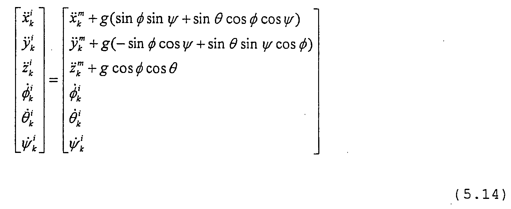
- the acceleration due to gravity must be calculated from the measured values according to equation (5.14).
- the Coriolis force that occurs during rotation is neglected.
- the initial conditions for the numerical integration are calculated from the measured values at time t 0 according to (5.15).
- the functions are assumed to be white Gaussian noise with the following boundary conditions: with the positively defined symmetric matrix Q k and r k > 0 for all k. It is also assumed that the initial conditions E ( x 0 ) and Var ( x 0 ) are known.
- the invention Visualization device and the invention Input device for all navigation concepts can be used where the interactions can be attributed to relative movements can.
- This system enables isometric interaction in all degrees of freedom.
- Interaction systems need for object manipulation other metaphors, such as voice input or combined head and hand tracking become.
- a differential Object selection can be carried out in the following way.
- When initiating an interaction becomes a representation of the interaction device on an assumed one Position shown relative to the head position.
- the coordinates of this object are based on the anthropometric data.
- the user moves this representation then with a constant Offset between the real hand and the visual one Presentation.
- the interactions must be timed be so short that the measured values of the visualization don't run away.
Landscapes
- Engineering & Computer Science (AREA)
- General Engineering & Computer Science (AREA)
- Theoretical Computer Science (AREA)
- Human Computer Interaction (AREA)
- Physics & Mathematics (AREA)
- General Physics & Mathematics (AREA)
- User Interface Of Digital Computer (AREA)
- Position Input By Displaying (AREA)
Abstract
Description
- Projektionssystem:
Auf der Basis unterschiedlicher Techniken wie z.B. Röhren- oder DLP-Projektoren werden die genierten Bildinformationen auf eine Projektionsscheibe oder Leinwand projiziert. Es wird zwischen aktivem und passivem Stereo unterschieden. Alternativ zu einem Projektionssystem werden Displaysysteme wie z.B. Datenhelm oder BOOM eingesetzt. - Projektionsscheibe oder Leinwand:
Die eingesetzten Projektionsscheiben oder -leinwände sind speziell bearbeitet, um einen guten Kontrast bei einer gleichmäßigen Helligkeitsverteilung zu gewährleisten. - Grafikrechner:
Je nach Anwendung werden Grafikworkstations mit mehreren Grafiksubsystemen oder ein Verbund mehrerer Rechner eingesetzt, um die Bildinformationen aus den digitalen Objekten zu generieren. - Tracking-System:
Typische Tracking-Systeme basieren auf der Vermessung künstlich generierter magnetischer Felder. Diese Systeme können die Lage eines Sensors in einem räumlich begrenzten Bereich messen. - Eingabesysteme:
Die Steuerung der Simulation erfolgt durch Eingabegeräte, die neben Tastern über einen Lagesensor verfügen. Die Auswertung der Sensordaten ermöglicht z.B. das Greifen von visualisierten Objekten.
- Figur 1
- ein kartesisches Koordinatensystem mit Bezeichnung der Achsen und Winkel;
- Figur 2
- eine Funktionsskizze für ein erfindungsgemäßes Visualisierungssystem;
- Figur 3
- ein Blockdiagramm einer erfindungsgemäßen Eingabevorrichtung;
- Figur 4
- einen Querschnitt durch eine erfindungsgemäße Eingabevorrichtung;
- Figur 5
- die Anordnung von Inertialsensoren in einer erfindungsgemäßen Eingabevorrichtung;
- Figur 6
- eine Übersicht der möglichen Interaktionen mit einer differenzialen Lagemessung;
- Figur 7
- die Darstellung eines Kugelmenüs;
- Figur 8
- die Darstellung eines ebenen Symbolmenüs;
- Figur 9
- die Darstellung eines transparenten Textmenüs; und
- Figur 10
- den Algorithmus eines diskreten Kalmanfilters.
- = [30°, -20°] Schwenken des Handgelenkes
- = [130°, -120°] links und rechts drehen der Hand gegenüber dem Rumpf.

"Tastenbyte" "Tab" i k "Tab" i / k Oxa Oxd


- Modus 1: Vorwärtsflug mit Beschleunigung Solange der Taster gedrückt ist, wird die Geschwindigkeit konstant erhöht.
- Modus 2: Rückwärtsflug mit Beschleunigung wie bei Modus 1, nur wird die Geschwindigkeit negativ erhöht.
- Modus 3: Stop
Stehenbleiben an der aktuellen Position

Die Selektion von Funktionen oder Softwaremodi kann mit diesem Interaktionsgerät über einen Taster für die Funktionen und die Sensorik gesteuert werden. Die Konzepte der Menüstrukturen werden im folgenden beschrieben.
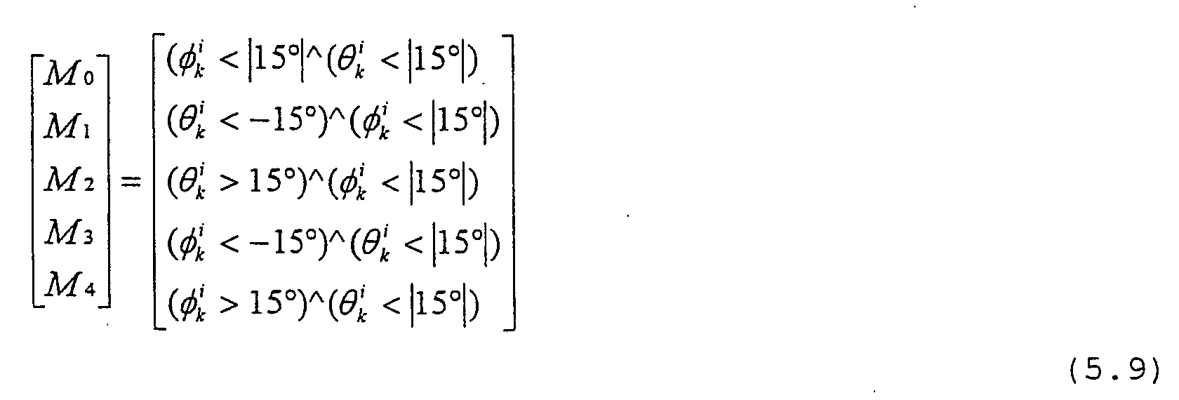
Figur 7 zeigt ein Kugelmenü, das zur Selektion von Funktionen oder Softwaremodi über einen Taster dienen kann. Bei einem derartigen Kugelmenü werden die Funktionen durch die Neigung um die x-Achse
i / k
und die Neigung um die y-Achse
i / k
ausgewählt. Die Menükugel ermöglicht die Selektion von 5 verschiedenen Optionen:
- Klick ohne Neigung (M0)
- Klick mit Neigung nach rechts bzw. links (M1, M2)
- Klick mit Neigung nach oben bzw. unten
(M3, M4)
Bei der Winkelauswertung wird immer nur eine Bewegung
berücksichtigt. Das System springt nach einer Verdrehung
von mindestens ± 15° in die nächste Funktionsstufe.
Figur 8 zeigt ein sogenanntes "Flat Icon Menü" (ebenes Symbol Menü).
i / k
nach einer bestimmten Neigungsbewegung immer auf den nächsten Menüpunkt. Eine vertikale Neigung
i / k
wählt innerhalb des Funktionsblockes die Untermenüs aus.
F h / n, F v / n
aufgeteilt. Der angezeigte Modus wechselt, sobald dieser Winkelbereich überschritten wird.
ψ i / k
gemessen. Die Winkelgeschwindigkeiten ωz werden über die Zeitdauer des gehaltenen Tasters integriert und ausgegeben.

ψ P / 0
vor. Die Geschwindigkeit in der x- bzw. y-Achse wird vom jeweiligen Neigungswinkel
i / k bzw. i / k
bestimmt. Die Rotation um die eigene Achse wird ebenfalls vom Interaktionsgerät vorgegeben. Damit bestimmt sich die Position des Benutzers nach (5.12).

ψ i / o
bei jedem Auslösen des Funktionstasters auf 0° gesetzt werden.
i / 0
und die Verdrehung um die z-Achse
ψ i / 0
ausgewählt. Die fünf Selektionsmöglichkeiten sind dann:
- Klick ohne Rotation (M0)
- Klick mit Rotation nach rechts bzw. nach links (M1, M2)
- Klick mit Neigung nach oben bzw. unten (M3, M4) .

ψ i 0
durchgeführt werden. Die vertikale Selektion funktioniert in derselben Weise wie in Kapitel 5.2.1 beschrieben.


und der vereinfachten Schreibweise


E(
bekannt sind. Der Algorithmus für den Kalman Filter berechnet sich dann mit der Kovarianzmatrix Pk,k-1 aus den Elementen:

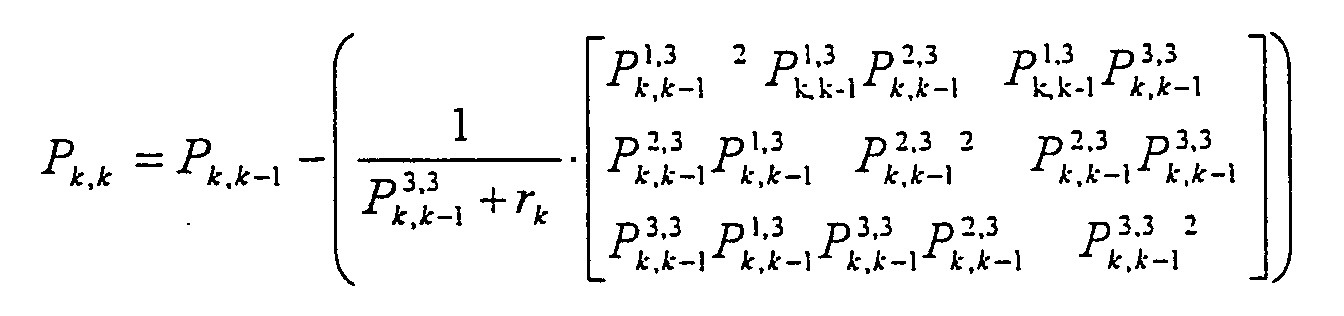
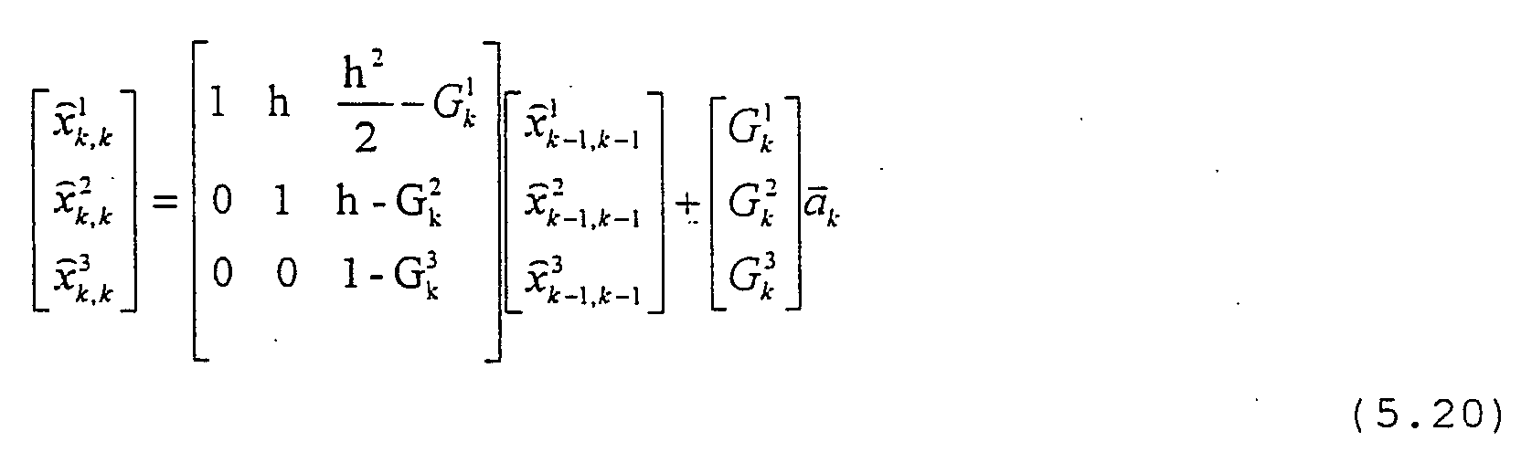
Claims (16)
- Handgehaltene, kabellose Eingabevorrichtung (4) zur Erzeugung und Übermittlung von Orts-, Lageund/oder Bewegungsdaten zur Navigation und Manipulation in Systemen der virtuellen Realität mit mindestens zwei Inertialsensoren (11, 12) zur Erfassung von analogen Werten der Beschleunigung und/oder der Winkelgeschwindigkeit der Eingabevorrichtung (4) mit einer ersten Frequenz,
einem integrierten Signalprozessor (13) zum Auswerten der von den Inertialsensoren (11, 12) ausgegebenen analogen Daten und Erzeugung digitaler differentialer Daten bezüglich der Bewegung der Eingabevorrichtung (4) mit einer niedrigen Frequenz, die geringer ist als die erste Frequenz,
einer Kommunikationsvorrichtung (17) zum kabellosen Senden der digitalen Daten niedriger Frequenz sowie
einer Auslösevorrichtung (14) , die die Inertialsensoren (11, 12) einschaltet. - Eingabevorrichtung (4) nach dem vorhergehenden Anspruch, dadurch gekennzeichnet, daß die Auslösevorrichtung (14) die Inertialsensoren (11, 12) für einen vorbestimmten Zeitraum einschaltet.
- Eingabevorrichtung (4) nach Anspruch 1, dadurch gekennzeichnet, daß die Auslösevorrichtung (14) die Inertialsensoren (11, 12) im eingeschalteten Zustand hält, solange sie betätigt wird.
- Eingabevorrichtung (4) nach einem der vorhergehenden Ansprüche, dadurch gekennzeichnet, daß als Inertialsensoren (11, 12)
ein bis drei Beschleunigungssensoren (11', 11'', 11''') zum Erfassen und Ausgeben von Beschleunigungswerten bezüglich einer oder mehrerer Achsen eines kartesischen Koordinatensystems mit einer bestimmten ersten Frequenz und/oder
ein bis drei Winkelgeschwindigkeitssensoren (12', 12'', 12''') zum Erfassen und Ausgeben von Winkelgeschwindigkeitswerten bezüglich einer oder mehrerer der Achsen des kartesischen Koordinatensystems mit-einer bestimmten zweiten Frequenz
vorgesehen sind. - Eingabevorrichtung (4) nach einem der vorhergehenden Ansprüche, dadurch gekennzeichnet, daß als Inertialsensor (11, 12) ein Kreiselsensor, ein Erdmagnetfeldsensor oder ein Beschleunigungssensor vorgesehen ist.
- Eingabevorrichtung (4) nach einem der vorhergehenden Ansprüche, dadurch gekennzeichnet, daß mit dem Signalprozessor (13) differentiale Daten mit einer Frequenz erzeugbar sind, die der Bildfrequenz einer Bilddarstellungsvorrichtung entspricht.
- Eingabevorrichtung (4) nach einem der vorhergehenden Ansprüche, dadurch gekennzeichnet, daß als Inertialsensor (11) ein Beschleunigungssensor verwendet wird und der Signalprozessor (13) aus den gemessenen Werten des Sensors in Ruhe der Eingabevorrichtung (4) die Lage der Eingabevorrichtung (4) ermittelt.
- Eingabevorrichtung (4) nach einem der vorhergehenden Ansprüche, dadurch gekennzeichnet, daß der Signalprozessor (8) die von den Inertialsensoren (11, 12) ausgegebenen analogen Daten einfach oder zweifach integriert.
- Eingabevorrichtung (4) nach dem vorhergehenden Anspruch, dadurch gekennzeichnet, daß die Integration mit Beginn-der Betätigung der Auslösevorrichtung (14) beginnt.
- Eingabevorrichtung (4) nach einem der beiden vorhergehenden Ansprüche, dadurch gekennzeichnet, daß die Anfangswerte der Winkel und der Ortskoordinaten zu Beginn jeder Betätigung der Auslösevorrichtung (14) zu 0 festgesetzt wird.
- Eingabevorrichtung (4) nach einem der beiden vorhergehenden Ansprüche, dadurch gekennzeichnet, daß der Signalprozessor (13) die Winkelgeschwindigkeit integriert und als Winkelwert ausgibt.
- Eingabevorrichtung (4) nach dem vorhergehenden Anspruch, dadurch gekennzeichnet, daß für die Integration der Anfangswert des Winkels zu 0° festgesetzt wird.
- Eingabevorrichtung (4) nach einem der vorhergehenden Ansprüche, dadurch gekennzeichnet, daß er als Inertialsensor (11, 12) einen Magnetfeldsensor aufweist, der den Anfangswinkel mit Bezug auf das Erdmagnetfeld bestimmt.
- Eingabevorrichtung (4) nach einem der vorhergehenden Ansprüche, dadurch gekennzeichnet, daß die Kommunikationsvorrichtung (17) einen Radiowellensender enthält.
- Eingabevorrichtung (4) nach einem der vorhergehenden Ansprüche, dadurch gekennzeichnet, daß die Kommunikationsvorrichtung (17) die Daten in ASCII-Format sendet.
- Visualisierungseinrichtung (1) zur Navigation und Manipulation in Systemen der virtuellen Realität mit einer Bilddarstellungsvorrichtung (2,3) zur Visualisierung von Daten und Bildern in Abhängigkeit von vorgegebenen Orts-, Lageund/oder Bewegungsdaten sowie einer Eingabevorrichtung (4) zur Erzeugung und Übermittlung der genannten Orts-, Lage- und/oder Bewegungsdaten nach einem der vorhergehenden Ansprüchen
Applications Claiming Priority (2)
| Application Number | Priority Date | Filing Date | Title |
|---|---|---|---|
| DE2001132243 DE10132243C2 (de) | 2001-07-04 | 2001-07-04 | Kabelloses Interaktionssystem für Anwendungen der virtuellen Realität |
| DE10132243 | 2001-07-04 |
Publications (2)
| Publication Number | Publication Date |
|---|---|
| EP1276073A2 true EP1276073A2 (de) | 2003-01-15 |
| EP1276073A3 EP1276073A3 (de) | 2006-11-15 |
Family
ID=7690468
Family Applications (1)
| Application Number | Title | Priority Date | Filing Date |
|---|---|---|---|
| EP02013065A Withdrawn EP1276073A3 (de) | 2001-07-04 | 2002-06-13 | Kabelloses Interaktionssystem für Anwendungen der virtuellen Realität |
Country Status (2)
| Country | Link |
|---|---|
| EP (1) | EP1276073A3 (de) |
| DE (1) | DE10132243C2 (de) |
Cited By (10)
| Publication number | Priority date | Publication date | Assignee | Title |
|---|---|---|---|---|
| US20020057088A1 (en) * | 1998-10-05 | 2002-05-16 | Alessandro Carrozzi | Machine for diagnostic and/or therapeutic treatment, particularly a nuclear magnetic resonance imaging machine |
| WO2005029306A3 (de) * | 2003-09-19 | 2005-06-23 | Icido Ges Fuer Innovative Info | Verfahren und vorrichtung zur steuerung eines graphiksystems der virtuellen realität mittels interaktionen |
| WO2005029302A3 (de) * | 2003-09-19 | 2005-11-17 | Icido Ges Fuer Innovative Info | Räumliche benutzungsschnittstelle zur steuerung eines graphiksystems der virtuellen realität mittels einer funktionsauswahl |
| US20060032110A1 (en) * | 2004-08-16 | 2006-02-16 | Keng-Ming Yang | Trapping device |
| FR2877113A1 (fr) * | 2004-10-22 | 2006-04-28 | Commissariat Energie Atomique | Dispositif autonome, systeme et procede de navigation dans un espace a au moins trois dimensions. |
| EP1441279A3 (de) * | 2003-01-21 | 2006-08-09 | Microsoft Corporation | Eingabegerät, das Trägheits-Sensoren integriert |
| EP1591873A3 (de) * | 2004-04-29 | 2006-12-06 | Samsung Electronics Co., Ltd. | Verfahren und Vorrichtung zur Eingabe von Informationen in ein tragbares elektronisches Gerät |
| US7262764B2 (en) | 2002-10-31 | 2007-08-28 | Microsoft Corporation | Universal computing device for surface applications |
| GB2477959A (en) * | 2010-02-19 | 2011-08-24 | Sony Europ | Navigation and display of an array of selectable items |
| US20110254844A1 (en) * | 2010-04-16 | 2011-10-20 | Sony Computer Entertainment Inc. | Three-dimensional image display device and three-dimensional image display method |
Families Citing this family (18)
| Publication number | Priority date | Publication date | Assignee | Title |
|---|---|---|---|---|
| US7133563B2 (en) | 2002-10-31 | 2006-11-07 | Microsoft Corporation | Passive embedded interaction code |
| US7116840B2 (en) | 2002-10-31 | 2006-10-03 | Microsoft Corporation | Decoding and error correction in 2-D arrays |
| DE10312154B4 (de) * | 2003-03-17 | 2007-05-31 | Fraunhofer-Gesellschaft zur Förderung der angewandten Forschung e.V. | Verfahren und Vorrichtung zum Ausführen einer Objektverfolgung |
| US7583842B2 (en) | 2004-01-06 | 2009-09-01 | Microsoft Corporation | Enhanced approach of m-array decoding and error correction |
| US7263224B2 (en) | 2004-01-16 | 2007-08-28 | Microsoft Corporation | Strokes localization by m-array decoding and fast image matching |
| DE102004057960A1 (de) * | 2004-12-01 | 2006-06-08 | Fraunhofer-Gesellschaft zur Förderung der angewandten Forschung e.V. | Computer-Eingabegerät |
| US7607076B2 (en) | 2005-02-18 | 2009-10-20 | Microsoft Corporation | Embedded interaction code document |
| US7826074B1 (en) | 2005-02-25 | 2010-11-02 | Microsoft Corporation | Fast embedded interaction code printing with custom postscript commands |
| US7421439B2 (en) | 2005-04-22 | 2008-09-02 | Microsoft Corporation | Global metadata embedding and decoding |
| US7599560B2 (en) | 2005-04-22 | 2009-10-06 | Microsoft Corporation | Embedded interaction code recognition |
| US7400777B2 (en) | 2005-05-25 | 2008-07-15 | Microsoft Corporation | Preprocessing for information pattern analysis |
| CN1870128B (zh) * | 2005-05-25 | 2011-11-23 | 光宝科技股份有限公司 | 混合乐曲的方法及装置 |
| US7729539B2 (en) | 2005-05-31 | 2010-06-01 | Microsoft Corporation | Fast error-correcting of embedded interaction codes |
| US7580576B2 (en) | 2005-06-02 | 2009-08-25 | Microsoft Corporation | Stroke localization and binding to electronic document |
| US7619607B2 (en) | 2005-06-30 | 2009-11-17 | Microsoft Corporation | Embedding a pattern design onto a liquid crystal display |
| US7817816B2 (en) | 2005-08-17 | 2010-10-19 | Microsoft Corporation | Embedded interaction code enabled surface type identification |
| US7622182B2 (en) | 2005-08-17 | 2009-11-24 | Microsoft Corporation | Embedded interaction code enabled display |
| DE102006055252B4 (de) | 2006-11-23 | 2019-03-28 | Deutsche Telekom Ag | Anordnung und Verfahren zur multimodalen Auswahl von Objekten in Telekommunikationsanwendungen |
Family Cites Families (8)
| Publication number | Priority date | Publication date | Assignee | Title |
|---|---|---|---|---|
| GB9011183D0 (en) * | 1990-05-18 | 1990-07-04 | British Aerospace | Control devices |
| US5453758A (en) * | 1992-07-31 | 1995-09-26 | Sony Corporation | Input apparatus |
| US5615132A (en) * | 1994-01-21 | 1997-03-25 | Crossbow Technology, Inc. | Method and apparatus for determining position and orientation of a moveable object using accelerometers |
| US6727887B1 (en) * | 1995-01-05 | 2004-04-27 | International Business Machines Corporation | Wireless pointing device for remote cursor control |
| US5703623A (en) * | 1996-01-24 | 1997-12-30 | Hall; Malcolm G. | Smart orientation sensing circuit for remote control |
| GB9613315D0 (en) * | 1996-06-25 | 1996-08-28 | Philips Electronics Nv | Virtual environment interaction and navigation device |
| US6148669A (en) * | 1998-06-29 | 2000-11-21 | U.S. Philips Corporation | Acceleration sensor with a spherical inductance influencing member |
| DE19845566A1 (de) * | 1998-09-04 | 2000-03-09 | Volkswagen Ag | Navigationsinterface zur Bewegung in virtuellen Welten |
-
2001
- 2001-07-04 DE DE2001132243 patent/DE10132243C2/de not_active Expired - Fee Related
-
2002
- 2002-06-13 EP EP02013065A patent/EP1276073A3/de not_active Withdrawn
Cited By (13)
| Publication number | Priority date | Publication date | Assignee | Title |
|---|---|---|---|---|
| US20020057088A1 (en) * | 1998-10-05 | 2002-05-16 | Alessandro Carrozzi | Machine for diagnostic and/or therapeutic treatment, particularly a nuclear magnetic resonance imaging machine |
| US7262764B2 (en) | 2002-10-31 | 2007-08-28 | Microsoft Corporation | Universal computing device for surface applications |
| EP1441279A3 (de) * | 2003-01-21 | 2006-08-09 | Microsoft Corporation | Eingabegerät, das Trägheits-Sensoren integriert |
| WO2005029306A3 (de) * | 2003-09-19 | 2005-06-23 | Icido Ges Fuer Innovative Info | Verfahren und vorrichtung zur steuerung eines graphiksystems der virtuellen realität mittels interaktionen |
| WO2005029302A3 (de) * | 2003-09-19 | 2005-11-17 | Icido Ges Fuer Innovative Info | Räumliche benutzungsschnittstelle zur steuerung eines graphiksystems der virtuellen realität mittels einer funktionsauswahl |
| EP1591873A3 (de) * | 2004-04-29 | 2006-12-06 | Samsung Electronics Co., Ltd. | Verfahren und Vorrichtung zur Eingabe von Informationen in ein tragbares elektronisches Gerät |
| US20060032110A1 (en) * | 2004-08-16 | 2006-02-16 | Keng-Ming Yang | Trapping device |
| WO2006045934A1 (fr) * | 2004-10-22 | 2006-05-04 | Commissariat A L'energie Atomique | Dispositif autonome, systeme et procede de navigation dans un espace a au moins trois dimensions |
| FR2877113A1 (fr) * | 2004-10-22 | 2006-04-28 | Commissariat Energie Atomique | Dispositif autonome, systeme et procede de navigation dans un espace a au moins trois dimensions. |
| US8072417B2 (en) | 2004-10-22 | 2011-12-06 | Commissariat A L'energie Atomique | Stand-alone device, system and method for navigating in a space having at least three dimensions |
| GB2477959A (en) * | 2010-02-19 | 2011-08-24 | Sony Europ | Navigation and display of an array of selectable items |
| US20110254844A1 (en) * | 2010-04-16 | 2011-10-20 | Sony Computer Entertainment Inc. | Three-dimensional image display device and three-dimensional image display method |
| US9204126B2 (en) * | 2010-04-16 | 2015-12-01 | Sony Corporation | Three-dimensional image display device and three-dimensional image display method for displaying control menu in three-dimensional image |
Also Published As
| Publication number | Publication date |
|---|---|
| DE10132243A1 (de) | 2003-01-23 |
| EP1276073A3 (de) | 2006-11-15 |
| DE10132243C2 (de) | 2003-04-30 |
Similar Documents
| Publication | Publication Date | Title |
|---|---|---|
| DE10132243C2 (de) | Kabelloses Interaktionssystem für Anwendungen der virtuellen Realität | |
| Zollmann et al. | Flyar: Augmented reality supported micro aerial vehicle navigation | |
| Brooks | What's real about virtual reality? | |
| CN104748746B (zh) | 智能机姿态测定及虚拟现实漫游方法 | |
| EP3283938B1 (de) | Gestenschnittstelle | |
| DE112013003257T5 (de) | Verbesserte Informationsübertragung durch ein transparentes Display | |
| EP3458939A1 (de) | Interaktionssystem und -verfahren | |
| ATE339720T1 (de) | VERFAHREN ZUR NAVIGATION IN EINEM SYNTHETISCHEN 3D-BILD DURCH 3D-BILDMANIPULATION, ßHYPER-3D- BROWSERß | |
| EP2325725A1 (de) | Verfahren zum reduzieren eines effekts auf virtuelle objekte | |
| DE10056291A1 (de) | Verfahren zur visuellen Darstellung und interaktiven Steuerung von virtuellen Objekten auf einem Ausgabe-Sichtfeld | |
| Leebmann | An augmented reality system for earthquake disaster response | |
| Murari et al. | Cross-Platform immersive visualization and navigation with augmented reality | |
| Beckhaus | Dynamic potential fields for guided exploration in virtual environments | |
| Friz | Design of an Augmented Reality User Interface for an Internet based Telerobot using Multiple Monoscopic Views | |
| CN103544677A (zh) | 空天地一体化态势表达引擎及其抖动消除方法 | |
| Ressler et al. | Applying virtual environments to manufacturing | |
| US20180292899A1 (en) | System and method for providing simulated environment | |
| Zeltzer et al. | A virtual environment system for mission planning | |
| Menezes et al. | Touching is believing-Adding real objects to Virtual Reality | |
| Huang et al. | Teleoperate system of underwater cleaning robot based on HUD | |
| Miles et al. | Designing a Virtual Toolkit for Analysing Planetary Science Data in Virtual Reality | |
| Ayyanchira et al. | Cross-platform immersive visualization and navigation with augmented reality | |
| Meyer et al. | Development and evaluation of an input method using virtual hand models for pointing to spatial objects in a stereoscopic desktop environment with a fitts’ pointing task | |
| Boy et al. | The virtual camera concept: a third person view | |
| Sukan | Augmented Reality Interfaces for Enabling Fast and Accurate Task Localization |
Legal Events
| Date | Code | Title | Description |
|---|---|---|---|
| PUAI | Public reference made under article 153(3) epc to a published international application that has entered the european phase |
Free format text: ORIGINAL CODE: 0009012 |
|
| AK | Designated contracting states |
Kind code of ref document: A2 Designated state(s): AT BE CH CY DE DK ES FI FR GB GR IE IT LI LU MC NL PT SE TR |
|
| AX | Request for extension of the european patent |
Free format text: AL;LT;LV;MK;RO;SI |
|
| RAP1 | Party data changed (applicant data changed or rights of an application transferred) |
Owner name: FRAUNHOFER-GESELLSCHAFT ZUR FOERDERUNG DERANGEWAND |
|
| PUAL | Search report despatched |
Free format text: ORIGINAL CODE: 0009013 |
|
| AK | Designated contracting states |
Kind code of ref document: A3 Designated state(s): AT BE CH CY DE DK ES FI FR GB GR IE IT LI LU MC NL PT SE TR |
|
| AX | Request for extension of the european patent |
Extension state: AL LT LV MK RO SI |
|
| RIC1 | Information provided on ipc code assigned before grant |
Ipc: G06F 3/033 20060101AFI20061011BHEP |
|
| RAP1 | Party data changed (applicant data changed or rights of an application transferred) |
Owner name: FRAUNHOFER-GESELLSCHAFT ZUR FOERDERUNG DER ANGEWAN |
|
| 17P | Request for examination filed |
Effective date: 20070227 |
|
| 17Q | First examination report despatched |
Effective date: 20070424 |
|
| AKX | Designation fees paid |
Designated state(s): AT BE CH CY DE DK ES FI FR GB GR IE IT LI LU MC NL PT SE TR |
|
| STAA | Information on the status of an ep patent application or granted ep patent |
Free format text: STATUS: THE APPLICATION IS DEEMED TO BE WITHDRAWN |
|
| 18D | Application deemed to be withdrawn |
Effective date: 20071025 |