EP1275912A1 - Refrigerator - Google Patents
Refrigerator Download PDFInfo
- Publication number
- EP1275912A1 EP1275912A1 EP01917766A EP01917766A EP1275912A1 EP 1275912 A1 EP1275912 A1 EP 1275912A1 EP 01917766 A EP01917766 A EP 01917766A EP 01917766 A EP01917766 A EP 01917766A EP 1275912 A1 EP1275912 A1 EP 1275912A1
- Authority
- EP
- European Patent Office
- Prior art keywords
- refrigerant
- pipe
- whose
- refrigeration system
- less
- Prior art date
- Legal status (The legal status is an assumption and is not a legal conclusion. Google has not performed a legal analysis and makes no representation as to the accuracy of the status listed.)
- Withdrawn
Links
Images



Classifications
-
- F—MECHANICAL ENGINEERING; LIGHTING; HEATING; WEAPONS; BLASTING
- F25—REFRIGERATION OR COOLING; COMBINED HEATING AND REFRIGERATION SYSTEMS; HEAT PUMP SYSTEMS; MANUFACTURE OR STORAGE OF ICE; LIQUEFACTION SOLIDIFICATION OF GASES
- F25B—REFRIGERATION MACHINES, PLANTS OR SYSTEMS; COMBINED HEATING AND REFRIGERATION SYSTEMS; HEAT PUMP SYSTEMS
- F25B13/00—Compression machines, plants or systems, with reversible cycle
-
- F—MECHANICAL ENGINEERING; LIGHTING; HEATING; WEAPONS; BLASTING
- F25—REFRIGERATION OR COOLING; COMBINED HEATING AND REFRIGERATION SYSTEMS; HEAT PUMP SYSTEMS; MANUFACTURE OR STORAGE OF ICE; LIQUEFACTION SOLIDIFICATION OF GASES
- F25B—REFRIGERATION MACHINES, PLANTS OR SYSTEMS; COMBINED HEATING AND REFRIGERATION SYSTEMS; HEAT PUMP SYSTEMS
- F25B9/00—Compression machines, plants or systems, in which the refrigerant is air or other gas of low boiling point
-
- C—CHEMISTRY; METALLURGY
- C09—DYES; PAINTS; POLISHES; NATURAL RESINS; ADHESIVES; COMPOSITIONS NOT OTHERWISE PROVIDED FOR; APPLICATIONS OF MATERIALS NOT OTHERWISE PROVIDED FOR
- C09K—MATERIALS FOR MISCELLANEOUS APPLICATIONS, NOT PROVIDED FOR ELSEWHERE
- C09K5/00—Heat-transfer, heat-exchange or heat-storage materials, e.g. refrigerants; Materials for the production of heat or cold by chemical reactions other than by combustion
- C09K5/02—Materials undergoing a change of physical state when used
- C09K5/04—Materials undergoing a change of physical state when used the change of state being from liquid to vapour or vice versa
- C09K5/041—Materials undergoing a change of physical state when used the change of state being from liquid to vapour or vice versa for compression-type refrigeration systems
- C09K5/044—Materials undergoing a change of physical state when used the change of state being from liquid to vapour or vice versa for compression-type refrigeration systems comprising halogenated compounds
- C09K5/045—Materials undergoing a change of physical state when used the change of state being from liquid to vapour or vice versa for compression-type refrigeration systems comprising halogenated compounds containing only fluorine as halogen
-
- F—MECHANICAL ENGINEERING; LIGHTING; HEATING; WEAPONS; BLASTING
- F04—POSITIVE - DISPLACEMENT MACHINES FOR LIQUIDS; PUMPS FOR LIQUIDS OR ELASTIC FLUIDS
- F04B—POSITIVE-DISPLACEMENT MACHINES FOR LIQUIDS; PUMPS
- F04B35/00—Piston pumps specially adapted for elastic fluids and characterised by the driving means to their working members, or by combination with, or adaptation to, specific driving engines or motors, not otherwise provided for
- F04B35/04—Piston pumps specially adapted for elastic fluids and characterised by the driving means to their working members, or by combination with, or adaptation to, specific driving engines or motors, not otherwise provided for the means being electric
-
- F—MECHANICAL ENGINEERING; LIGHTING; HEATING; WEAPONS; BLASTING
- F25—REFRIGERATION OR COOLING; COMBINED HEATING AND REFRIGERATION SYSTEMS; HEAT PUMP SYSTEMS; MANUFACTURE OR STORAGE OF ICE; LIQUEFACTION SOLIDIFICATION OF GASES
- F25B—REFRIGERATION MACHINES, PLANTS OR SYSTEMS; COMBINED HEATING AND REFRIGERATION SYSTEMS; HEAT PUMP SYSTEMS
- F25B41/00—Fluid-circulation arrangements
- F25B41/40—Fluid line arrangements
-
- F—MECHANICAL ENGINEERING; LIGHTING; HEATING; WEAPONS; BLASTING
- F25—REFRIGERATION OR COOLING; COMBINED HEATING AND REFRIGERATION SYSTEMS; HEAT PUMP SYSTEMS; MANUFACTURE OR STORAGE OF ICE; LIQUEFACTION SOLIDIFICATION OF GASES
- F25B—REFRIGERATION MACHINES, PLANTS OR SYSTEMS; COMBINED HEATING AND REFRIGERATION SYSTEMS; HEAT PUMP SYSTEMS
- F25B9/00—Compression machines, plants or systems, in which the refrigerant is air or other gas of low boiling point
- F25B9/002—Compression machines, plants or systems, in which the refrigerant is air or other gas of low boiling point characterised by the refrigerant
-
- F—MECHANICAL ENGINEERING; LIGHTING; HEATING; WEAPONS; BLASTING
- F25—REFRIGERATION OR COOLING; COMBINED HEATING AND REFRIGERATION SYSTEMS; HEAT PUMP SYSTEMS; MANUFACTURE OR STORAGE OF ICE; LIQUEFACTION SOLIDIFICATION OF GASES
- F25B—REFRIGERATION MACHINES, PLANTS OR SYSTEMS; COMBINED HEATING AND REFRIGERATION SYSTEMS; HEAT PUMP SYSTEMS
- F25B9/00—Compression machines, plants or systems, in which the refrigerant is air or other gas of low boiling point
- F25B9/002—Compression machines, plants or systems, in which the refrigerant is air or other gas of low boiling point characterised by the refrigerant
- F25B9/006—Compression machines, plants or systems, in which the refrigerant is air or other gas of low boiling point characterised by the refrigerant the refrigerant containing more than one component
-
- C—CHEMISTRY; METALLURGY
- C09—DYES; PAINTS; POLISHES; NATURAL RESINS; ADHESIVES; COMPOSITIONS NOT OTHERWISE PROVIDED FOR; APPLICATIONS OF MATERIALS NOT OTHERWISE PROVIDED FOR
- C09K—MATERIALS FOR MISCELLANEOUS APPLICATIONS, NOT PROVIDED FOR ELSEWHERE
- C09K2205/00—Aspects relating to compounds used in compression type refrigeration systems
- C09K2205/22—All components of a mixture being fluoro compounds
-
- C—CHEMISTRY; METALLURGY
- C09—DYES; PAINTS; POLISHES; NATURAL RESINS; ADHESIVES; COMPOSITIONS NOT OTHERWISE PROVIDED FOR; APPLICATIONS OF MATERIALS NOT OTHERWISE PROVIDED FOR
- C09K—MATERIALS FOR MISCELLANEOUS APPLICATIONS, NOT PROVIDED FOR ELSEWHERE
- C09K2205/00—Aspects relating to compounds used in compression type refrigeration systems
- C09K2205/24—Only one single fluoro component present
-
- F—MECHANICAL ENGINEERING; LIGHTING; HEATING; WEAPONS; BLASTING
- F25—REFRIGERATION OR COOLING; COMBINED HEATING AND REFRIGERATION SYSTEMS; HEAT PUMP SYSTEMS; MANUFACTURE OR STORAGE OF ICE; LIQUEFACTION SOLIDIFICATION OF GASES
- F25B—REFRIGERATION MACHINES, PLANTS OR SYSTEMS; COMBINED HEATING AND REFRIGERATION SYSTEMS; HEAT PUMP SYSTEMS
- F25B2400/00—Component parts or details not otherwise provided for in this subclass
- F25B2400/12—Inflammable refrigerants
-
- F—MECHANICAL ENGINEERING; LIGHTING; HEATING; WEAPONS; BLASTING
- F25—REFRIGERATION OR COOLING; COMBINED HEATING AND REFRIGERATION SYSTEMS; HEAT PUMP SYSTEMS; MANUFACTURE OR STORAGE OF ICE; LIQUEFACTION SOLIDIFICATION OF GASES
- F25B—REFRIGERATION MACHINES, PLANTS OR SYSTEMS; COMBINED HEATING AND REFRIGERATION SYSTEMS; HEAT PUMP SYSTEMS
- F25B2400/00—Component parts or details not otherwise provided for in this subclass
- F25B2400/18—Refrigerant conversion
-
- F—MECHANICAL ENGINEERING; LIGHTING; HEATING; WEAPONS; BLASTING
- F25—REFRIGERATION OR COOLING; COMBINED HEATING AND REFRIGERATION SYSTEMS; HEAT PUMP SYSTEMS; MANUFACTURE OR STORAGE OF ICE; LIQUEFACTION SOLIDIFICATION OF GASES
- F25B—REFRIGERATION MACHINES, PLANTS OR SYSTEMS; COMBINED HEATING AND REFRIGERATION SYSTEMS; HEAT PUMP SYSTEMS
- F25B2500/00—Problems to be solved
- F25B2500/01—Geometry problems, e.g. for reducing size
Definitions
- the present invention relates to refrigeration systems. More particularly, this invention relates to a refrigeration system which employs either a single refrigerant of R32 or an R32 containing mixed refrigerant.
- a conventional refrigeration system which comprises a refrigerant circuit including a compressor, a condenser, a pressure reducing mechanism, and an evaporator and the refrigerant circuit forms a refrigeration cycle using an HCFC refrigerant such as R22.
- the compressor plays an important role of increasing the pressure of the refrigerant. Therefore, refrigeration oil is required for smooth operation of the compressor.
- refrigeration systems employing an HFC refrigerant use a synthetic oil as a refrigeration oil.
- Contamination with air and moisture occurs at the time of manufacture of the element devices of the refrigerant circuit and at the time of installation of the system in the field. Therefore, the amount of such contamination can be reduced by making a change in the manufacture method and process and by reinforcing the product quality control at the time of manufacture of the system.
- an object of the present invention is to provide improvements in system reliability as well as in system handling ease.
- the present invention utilizes a resin material as an insulating material for use in an electric motor of a compressor and employs a refrigerant of less pressure loss (e.g., an R32 single refrigerant or R32 mixed refrigerant) in comparison with the R22 or the like.
- a refrigerant of less pressure loss e.g., an R32 single refrigerant or R32 mixed refrigerant
- the present invention was made based on the following reasons. That is, by reason of the fact that an R32 single refrigerant (or an R32 mixed refrigerant) provides a greater refrigeration effect in comparison with R22, R407C, and R410A, less amounts of circulating refrigerant necessary for obtaining the same capacity are required in comparison with, for example, the R22. Therefore, for the case of the R32 single refrigerant (or the R32 mixed refrigerant), its pressure loss is smaller in comparison with, for example, the R22, when flowing through a flowpath of the same diameter.
- the refrigerant pipe includes a liquid side pipe.
- the liquid side pipe is a pipe extending, for example, from a condenser outlet to an evaporator inlet.
- the liquid side pipe does not cause a drop in the system performance even when there is an increase in the pressure loss, as long as that increase falls within the control range of the pressure reducing mechanism (for example a capillary tube and an expansion valve).
- the pressure reducing mechanism for example a capillary tube and an expansion valve.
- the high-low pressure difference in the refrigerant circuit is, at most, about 1.6 times greater than when the R22 refrigerant is employed.
- the allowable range for refrigerant pressure loss extends. Accordingly, when the R32 single refrigerant (or the R32 mixed refrigerant) is employed, it is possible to further reduce the diameter of the liquid side pipe than conventional, without a drop in the system performance.
- the refrigerant pipe further includes a discharge pipe and a suction pipe.
- the discharge pipe is a pipe extending, for example, from a compressor discharge side to a condenser inlet
- the suction pipe is a pipe extending, for example, from an evaporator outlet to a compressor suction side.
- the pressure loss of these discharge and suction pipes considerably affects the system performance.
- the utilization of the R32 single refrigerant (or the R32 mixed refrigerant) decreases the pressure loss to a further extent than conventional. This shows that, even when the diameter of the discharge and suction pipes is reduced, the utilization of an R32 single refrigerant (or an R32 mixed refrigerant) makes it possible to maintain the same system performance as conventional.
- the R32 single refrigerant (or the R32 mixed refrigerant) makes it possible to reduce the pipe diameter to some extent while maintaining superiority in performance to conventional systems.
- saturation temperature difference equivalent to the amount of refrigerant pressure loss becomes important.
- the pressure loss is small. Therefore, even when the diameter of a heat transfer pipe of the heat exchanger is reduced, the saturation temperature difference can become the same as conventional.
- both the R32 single refrigerant and the R32 mixed refrigerant have a higher heat transfer rate than conventional. Therefore, even when a heat transfer pipe has a reduction in diameter, it is able to maintain the heat exchanging capacity at high levels.
- the inventor of the present invention found out that, even when an R32 single refrigerant (or an R32 mixed refrigerant) is employed to reduce the diameter of a refrigerant pipe and the diameter of a heat exchanger heat transfer pipe for reducing the internal volume of a refrigerant circuit, there occurs no problem with the system performance at all. On the other hand, the amount of air or moisture contamination in a refrigerant circuit increases in proportion to the internal volume of a refrigerant circuit.
- the internal volume of a refrigerant circuit is reduced by utilization of an R32 single refrigerant (or an R32 mixed refrigerant) so that the amount of air or moisture contamination which is introduced into the refrigerant circuit can be reduced, and the deterioration of an insulating material used in an electric motor of the compressor is prevented.
- HFC refrigeration systems employ a synthetic oil as a refrigeration oil.
- a synthetic oil there are ether oil and ester oil having compatibility with refrigerant.
- alkylbenzene oil which exhibits poor compatibility with refrigerant but is able to secure the performance of returning oil by viscosity reduction.
- the synthetic oil is more susceptible to chemical reaction such as decomposition, polymerization and so forth, when the refrigerant circuit is contaminated with air or moisture.
- part of the synthetic oil is deposited in the form of a sludge in an expansion valve or in a capillary tube, which may cause clogging of a flowpath of the refrigerant circuit.
- ether oil and alkylbenzene oil are susceptible to oxidative deterioration by air and ester oil is hydrolyzed when contaminated with moisture. As a result, the total acid number of each synthetic oil increases.
- insulating material such as insulating paper, a lead wire, a tying cord, or the like has been utilized for compressor electric motors.
- Such an insulating material is a resin material.
- the insulating material is for example polyethylene terephthalate (PET), polyethylene naphthalate (PEN), polyphenylene sulfide (PPS), polybutylene terephthalate (PBT), polyether ether ketone (PEEK), polyamide imide (PAI), or polyimide.
- any of these resin materials undergoes a drop in strength, e.g., a drop in tensile strength, during the rise in total acid number. This may give rise to burning out of the electric motor.
- an R32 single refrigerant (or an R32 mixed refrigerant) is employed to reduce the internal volume of a refrigerant circuit. Because of this, the amount of air or moisture contamination in the refrigerant circuit can be reduced. Because of such a reduction in the amount of air or moisture contamination, the deterioration of an insulating material for an electric motor of a compressor can be prevented.
- an R32 single refrigerant or a mixed refrigerant whose R32 content is not less than 75% is employed and a resin material is utilized as an insulating material for an electric motor in a compressor (11) .
- Another invention is directed to a refrigeration system whose cooling rated capacity is not more than 5 kW, the refrigeration system comprising a refrigerant circuit (10) which forms a refrigeration cycle in which either an R32 single refrigerant or a mixed refrigerant whose R32 content is not less than 75% is used as a refrigerant and includes a compressor (11) which utilizes a resin material as an electric motor insulating material.
- the refrigerant circuit (10) includes a liquid side pipe (32) which is formed by use of a pipe whose inside diameter is less than 4.75 mm.
- Still another invention is directed to a refrigeration system whose cooling rated capacity is not more than 5 kW, the refrigeration system comprising a refrigerant circuit (10) which forms a refrigeration cycle in which either an R32 single refrigerant or a mixed refrigerant whose R32 content is not less than 75% is used as a refrigerant and includes a compressor (11) which utilizes a resin material as an electric motor insulating material.
- the refrigerant circuit (10) includes a liquid side pipe (32) which is formed by use of a pipe whose inside diameter ranges from 3.2 mm to 4.2 mm.
- a further invention is directed to a refrigeration system whose cooling rated capacity is not more than 5 kW, the refrigeration system comprising a refrigerant circuit (10) which forms a refrigeration cycle in which either an R32 single refrigerant or a mixed refrigerant whose R32 content is not less than 75% is used as a refrigerant and includes a compressor (11) which utilizes a resin material as an electric motor insulating material.
- the refrigerant circuit (10) includes a liquid side pipe (32) which is formed by use of a pipe whose inside diameter ranges from 3.5 mm to 3.9 mm.
- a still further invention is directed to a refrigeration system whose cooling rated capacity is not more than 5 kW, the refrigeration system comprising a refrigerant circuit (10) which forms a refrigeration cycle in which either an R32 single refrigerant or a mixed refrigerant whose R32 content is not less than 75% is used as a refrigerant and includes a compressor (11) which utilizes a resin material as an electric motor insulating material.
- the refrigerant circuit (10) includes a liquid side pipe (32) which is formed by use of a pipe whose inside diameter ranges from 3.6 mm to 3.8 mm.
- Another invention is directed to a refrigeration system whose cooling rated capacity is greater than 5 kW but not more than 18 kW, the refrigeration system comprising a refrigerant circuit (10) which forms a refrigeration cycle in which either an R32 single refrigerant or a mixed refrigerant whose R32 content is not less than 75% is used as a refrigerant and includes a compressor (11) which utilizes a resin material as an electric motor insulating material.
- the refrigerant circuit (10) includes a liquid side pipe (32) which is formed by use of a pipe whose inside diameter is less than 7.92 mm.
- Still another invention is directed to a refrigeration system whose cooling rated capacity is greater than 18 kW but not more than 22.4 kW, the refrigeration system comprising a refrigerant circuit (10) which forms a refrigeration cycle in which either an R32 single refrigerant or a mixed refrigerant whose R32 content is not less than 75% is used as a refrigerant and includes a compressor (11 ) which utilizes a resin material as an electric motor insulating material.
- the refrigerant circuit (10) includes a liquid side pipe (32) which is formed by use of a pipe whose inside diameter is less than 11.1 mm.
- a further invention is directed to a refrigeration system whose cooling rated capacity is greater than 5 kW but not more than 22.4 kW, the refrigeration system comprising a refrigerant circuit (10) which forms a refrigeration cycle in which either an R32 single refrigerant or a mixed refrigerant whose R32 content is not less than 75% is used as a refrigerant and includes a compressor (11) which utilizes a resin material as an electric motor insulating material.
- the refrigerant circuit (10) includes a liquid side pipe (32) which is formed by use of a pipe whose inside diameter ranges from 5.4 mm to 7.0 mm.
- a still further invention is directed to a refrigeration system whose cooling rated capacity is greater than 5 kW but not more than 22.4 kW, the refrigeration system comprising a refrigerant circuit (10) which forms a refrigeration cycle in which either an R32 single refrigerant or a mixed refrigerant whose R32 content is not less than 75% is used as a refrigerant and includes a compressor (11) which utilizes a resin material as an electric motor insulating material.
- the refrigerant circuit (10) includes a liquid side pipe (32) which is formed by use of a pipe whose inside diameter ranges from 5.7 mm to 6.7 mm.
- Another invention is directed to a refrigeration system whose cooling rated capacity is greater than 5 kW but not more than 22.4 kW, the refrigeration system comprising a refrigerant circuit (10) which forms a refrigeration cycle in which either an R32 single refrigerant or a mixed refrigerant whose R32 content is not less than 75% is used as a refrigerant and includes a compressor (11) which utilizes a resin material as an electric motor insulating material.
- the refrigerant circuit (10) includes a liquid side pipe (32) which is formed by use of a pipe whose inside diameter ranges from 6.0 mm to 6.4 mm.
- Still another invention is directed to a refrigeration system whose cooling rated capacity is so designed as to be greater than 22.4 kW, the refrigeration system comprising a refrigerant circuit (10) which forms a refrigeration cycle in which either an R32 single refrigerant or a mixed refrigerant whose R32 content is not less than 75% is used as a refrigerant and includes a compressor (11) which utilizes a resin material as an electric motor insulating material.
- the refrigerant circuit (10) includes a liquid side pipe (32) which is formed by use of a pipe whose inside diameter is less than 13.88 mm.
- a further invention is directed to a refrigeration system whose cooling rated capacity is so designed as to be greater than 22.4 kW, the refrigeration system comprising a refrigerant circuit (10) which forms a refrigeration cycle in which either an R32 single refrigerant or a mixed refrigerant whose R32 content is not less than 75% is used as a refrigerant and includes a compressor (11) which utilizes a resin material as an electric motor insulating material.
- the refrigerant circuit (10) includes a liquid side pipe (32) which is formed by use of a pipe whose inside diameter ranges from 7.5 mm to 9.8 mm.
- a still further invention is directed to a refrigeration system whose cooling rated capacity is so designed as to be greater than 22.4 kW, the refrigeration system comprising a refrigerant circuit (10) which forms a refrigeration cycle in which either an R32 single refrigerant or a mixed refrigerant whose R32 content is not less than 75% is used as a refrigerant and includes a compressor (11) which utilizes a resin material as an electric motor insulating material.
- the refrigerant circuit (10) includes a liquid side pipe (32) which is formed by use of a pipe whose inside diameter ranges from 7.8 mm to 9.5 mm.
- Another invention is directed to a refrigeration system whose cooling rated capacity is so designed as to be greater than 22.4 kW, the refrigeration system comprising a refrigerant circuit (10) which forms a refrigeration cycle in which either an R32 single refrigerant or a mixed refrigerant whose R32 content is not less than 75% is used as a refrigerant and includes a compressor (11) which utilizes a resin material as an electric motor insulating material.
- the refrigerant circuit (10) includes a liquid side pipe (32) which is formed by use of a pipe whose inside diameter ranges from 8.1 mm to 9.1 mm.
- Still another invention is directed to a refrigeration system whose cooling rated capacity is not more than 3.2 kW, the refrigeration system comprising a refrigerant circuit (10) which forms a refrigeration cycle in which either an R32 single refrigerant or a mixed refrigerant whose R32 content is not less than 75% is used as a refrigerant and includes a compressor (11 ) which utilizes a resin material as an electric motor insulating material.
- the refrigerant circuit (10) includes a gas side pipe (31) which is formed by use of a pipe whose inside diameter is less than 7.92 mm.
- a further invention is directed to a refrigeration system whose cooling rated capacity is greater than 3.2 kW but not more than 5 kW, the refrigeration system comprising a refrigerant circuit (10) which forms a refrigeration cycle in which either an R32 single refrigerant or a mixed refrigerant whose R32 content is not less than 75% is used as a refrigerant and includes a compressor (11) which utilizes a resin material as an electric motor insulating material.
- the refrigerant circuit (10) includes a gas side pipe (31) which is formed by use of a pipe whose inside diameter is less than 11.1 mm.
- a still further invention is directed to a refrigeration system whose cooling rated capacity is greater than 5 kW but not more than 9 kW, the refrigeration system comprising a refrigerant circuit (10) which forms a refrigeration cycle in which either an R32 single refrigerant or a mixed refrigerant whose R32 content is not less than 75% is used as a refrigerant and includes a compressor (11) which utilizes a resin material as an electric motor insulating material.
- the refrigerant circuit (10) includes a gas side pipe (31) which is formed by use of a pipe whose inside diameter is less than 13.88 mm.
- Another invention is directed to a refrigeration system whose cooling rated capacity is greater than 9 kW but not more than 18 kW, the refrigeration system comprising a refrigerant circuit (10) which forms a refrigeration cycle in which either an R32 single refrigerant or a mixed refrigerant whose R32 content is not less than 75% is used as a refrigerant and includes a compressor (11) which utilizes a resin material as an electric motor insulating material.
- the refrigerant circuit (10) includes a gas side pipe (31) which is formed by use of a pipe whose inside diameter is less than 17.05 mm.
- Still another invention is directed to a refrigeration system whose cooling rated capacity is greater than 18 kW but not more than 22.4 kW, the refrigeration system comprising a refrigerant circuit (10) which forms a refrigeration cycle in which either an R32 single refrigerant or a mixed refrigerant whose R32 content is not less than 75% is used as a refrigerant and includes a compressor (11) which utilizes a resin material as an electric motor insulating material.
- the refrigerant circuit (10) includes a gas side pipe (31) which is formed by use of a pipe whose inside diameter is less than 23.4 mm.
- a further invention is directed to a refrigeration system whose cooling rated capacity is so designed as to be greater than 22.4 kW, the refrigeration system comprising a refrigerant circuit (10) which forms a refrigeration cycle in which either an R32 single refrigerant or a mixed refrigerant whose R32 content is not less than 75% is used as a refrigerant and includes a compressor (11) which utilizes a resin material as an electric motor insulating material.
- the refrigerant circuit (10) includes a gas side pipe (31) which is formed by use of a pipe whose inside diameter is less than 26.18 mm.
- a still further invention is directed to a refrigeration system comprising a refrigerant circuit (10) which includes (a) a compressor (11) which utilizes a resin material as an electric motor insulating material and (b) an indoor heat exchanger (15) and forms a refrigeration cycle in which either an R32 single refrigerant or a mixed refrigerant whose R32 content is not less than 75% is used as a refrigerant.
- the indoor heat exchanger (15) includes a heat transfer pipe which is formed by use of a heat transfer pipe whose inside diameter is less than 5.87 mm.
- Another invention is directed to a refrigeration system comprising a refrigerant circuit (10) which includes (a) a compressor (11) which utilizes a resin material as an electric motor insulating material and (b) an outdoor heat exchanger (13) and forms a refrigeration cycle in which either an R32 single refrigerant or a mixed refrigerant whose R32 content is not less than 75% is used as a refrigerant.
- the outdoor heat exchanger (13) includes a heat transfer pipe which is formed by use of a heat transfer pipe whose inside diameter is less than 6.89 mm.
- Still another invention is directed to a refrigeration system
- a refrigerant circuit (10) which includes (a) a compressor (11) which utilizes a resin material as an electric motor insulating material and (b) an outdoor heat exchanger (13) and forms a refrigeration cycle in which either an R32 single refrigerant or a mixed refrigerant whose R32 content is not less than 75% is used as a refrigerant.
- the outdoor heat exchanger (13) includes a heat transfer pipe which is formed by use of a heat transfer pipe whose inside diameter is less than 7.99 mm.
- the compressor (11) may use a synthetic oil as a refrigeration oil.
- liquid side pipe (32) may be a liquid side connecting pipe for connecting an indoor unit (17) and an outdoor unit (16) .
- gas side pipe (31) may be a gas side connecting pipe for connecting an indoor unit (17) and an outdoor unit (16) .
- the mixed refrigerant is an R32/R125 mixed refrigerant.
- the refrigerant may be an R32 single refrigerant.
- the present invention makes it possible to reduce the internal volume of the refrigerant circuit (10) , thereby making it possible to reduce the amount of air contamination, moisture contamination, or other contamination which is introduced into the refrigerant circuit (10) .
- the expansion mechanism such as a capillary tube can be prevented from clogging, for example. Accordingly, it is possible to achieve the reduction in fraction defective.
- a refrigeration system of the present embodiment is an air conditioning system (1) formed by connection of an outdoor unit (16) which is a heat source unit and an indoor unit (17) which is a utilization unit.
- a refrigerant circuit (10) of the air conditioning system (1) employs, as its refrigerant, either a single refrigerant of R32 (hereinafter referred to as the R32 single refrigerant) or a mixed refrigerant comprising R32 and R125 in which the R32 content is not less than 75% but less than 100% by weight (i.e., an R32 composition rich mixed refrigerant which is hereinafter called the R32/R125 mixed refrigerant).
- the refrigerant circuit (10) is a refrigerant circuit which forms a vapor compression refrigeration cycle.
- the refrigerant circuit (10) is formed by connecting, in series in the order given, a compressor (11), a four-way selector valve (12), an outdoor heat exchanger (13) which is a heat source side heat exchanger, an expansion valve (14) which is an expansion mechanism, and an indoor heat exchanger (15) which is a utilization side heat exchanger, by a gas side pipe (31) and a liquid side pipe (32).
- These pipes (31) and (32) are refrigerant pipes.
- a discharge side of the compressor (11) and a first port (12a) of the four-way selector valve (12) are connected together by a first gas side pipe (21).
- a second port (12b) of the four-way selector valve (12) and the outdoor heat exchanger (13) are connected together by a second gas side pipe (22).
- the outdoor heat exchanger (13) and the expansion valve (14) are connected together by a first liquid side pipe (25).
- the expansion valve (14) and the indoor heat exchanger (15) are connected together by a second liquid side pipe (26).
- the indoor heat exchanger (15) and a third port (12c) of the four-way selector valve (12) are connected together by a third gas side pipe (23).
- a fourth port (12d) of the four-way selector valve (12) and a suction side of the compressor (11) are connected together by a fourth gas side pipe (24).
- the compressor (11), the first gas side pipe (21), the four-way selector valve (12), the second gas side pipe (22) , the outdoor heat exchanger (13) , the first liquid side pipe (25) , the expansion valve (14) , and the fourth gas side pipe (24) are all housed in an outdoor unit (16), together with an outdoor air blower (not shown).
- the indoor heat exchanger (15) is housed in an indoor unit (17), together with an indoor air blower (not shown).
- a part of the second liquid side pipe (26) and a part of the third gas side pipe (23) constitute a so-called connecting pipe for establishing connection between the outdoor unit (16) and the indoor unit (17) .
- a synthetic oil is used as a refrigeration oil.
- a synthetic oil comprises ether oil, ester oil, or the like.
- alkylbenzene oil may be used.
- the refrigeration oil is added with an extreme pressure additive.
- an extreme pressure additive additives of the phosphorus family such as phosphoric ester and phosphite may be used.
- additives of the chlorine family and additives of the sulfur family may be used.
- an electric motor (not shown) of the compressor (11) is housed in the casing.
- insulating material such as insulating paper, a lead wire, a tying cord and the like is used.
- Such an insulating material comprises a resin material.
- the insulating material comprises polyethylene terephthalate (PET), polyethylene naphthalate (PEN), polyphenylene sulfide (PPS), polybutylene terephthalate (PBT), polyether ether ketone (PEEK), polyamide imide (PAI), polyimide, or the like.
- the insulating paper, the lead wire, and the typing cord are formed by use of these resin materials.
- the insulating paper may be formed of PET and the lead wire may be formed of PPS, and plural types of resin materials may be utilized in the compressor electric motor.
- Ether oil and alkylbenzene oil are susceptible to oxidative deterioration by air. Ester oil is hydrolyzed by moisture contamination. As a result, the total acid number of any of the synthetic oils increases.
- any of these resin materials undergoes a drop in strength such as a drop in tensile strength during the rise in total acid number. This may give rise to burning out of the electric motor in the worst case.
- the refrigeration oil is added with an extreme pressure additive for the prevention of abrasion and seizing of a sliding part of the compressor (11) .
- an extreme pressure additive is added to the refrigeration oil.
- Such an extreme pressure additive is hydrolyzed when a sliding surface of the compressor (11) is at high temperatures and when existing together with moisture and, as a result, there is a drop in the lubricity.
- the extreme pressure additive may be deposited in the form of a sludge in the expansion valve (14).
- chlorine-family extreme pressure additives may produce a corrosive substance.
- an R32 single refrigerant (or an R32/R125 mixed refrigerant) is used to diminish the internal volume of the refrigerant circuit (10), for reducing the amount of air or moisture contamination.
- the R32 single refrigerant (or the R32/R125 mixed refrigerant) exhibits a greater refrigeration effect per unit volume than that of the R22, the former requires a less amount of circulating refrigerant for achieving a specified capacity in comparison with the later. Therefore, for the case of the R32 single refrigerant (or the R32/R125 mixed refrigerant), the amount of circulating refrigerant can be reduced, provided that heat exchanger's heat transfer pipes of the same inside diameter are used. As a result, the loss of tube pressure becomes smaller in comparison with the R22.
- the diameter of the heat transfer pipes of the outdoor heat exchanger (13) and indoor heat exchanger (15) is reduced to such an extent that the loss of tube pressure is at the same level as the R22. More specifically, in the air conditioning system (1) of the present invention, the amount of variation in the refrigerant saturation temperature corresponding to the amount of pressure loss in the heat transfer pipe is taken into account and the inside diameter dimension of the outdoor heat exchanger (13) and indoor heat exchanger (15) is set so that the temperature variation amount becomes the same as that of the R22.
- the pressure loss ⁇ P is calculated using the following expression which is a friction loss expression for annular pipes.
- ⁇ P ⁇ L/d ⁇ G 2 /2 ⁇ s ⁇ A 2
- the inside diameter ratio of an R32 heat transfer pipe to an R22 heat transfer pipe i.e., the heat transfer pipe diameter reducing ratio
- ⁇ T/ ⁇ P ⁇ 22 ⁇ ( ⁇ h 22 2 ⁇ s 22 ⁇ d 22 5 ) -1 ⁇ T/ ⁇ P ⁇ 32 ⁇ ( ⁇ h 32 2 ⁇ s 32 ⁇ d 32 5 ) -1
- d 32 /d 22 (( ⁇ h 32 / ⁇ h 22 ) 2 ⁇ ⁇ s 32 / ⁇ s 22 ⁇ ( ⁇ T/ ⁇ P ⁇ 32 / ⁇ T/ ⁇ P ⁇ 22 ) -1 ) -1/5
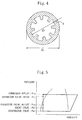
- the calculation results show that the diameter of the R32 heat transfer pipe can be reduced about 0.76 times that of the R22 heat transfer pipe. Further, the calculation results show that the diameter of the R32/R125 heat transfer pipe can be reduced about from 0.76 to 0.8 times that of the R22 heat transfer pipe. The same calculations were performed on other replacement refrigerants for reference and the calculation results show that none of them achieved better diameter reduction than the R32 (see Figure 3 ).
- heat transfer pipes having the following inside diameters are employed, for comparison with the R22 heat transfer pipe.
- the heat transfer pipe of the indoor heat exchanger (15) is formed by use of a heat transfer pipe whose inside diameter is in the range of 4.7 mm to 5.9 mm
- the heat transfer pipe of the outdoor heat exchanger (13) is formed by use of a heat transfer pipe whose inside diameter is in the range of 5.4 mm to 6.7 mm.
- the heat transfer pipe of the indoor heat exchanger (15) is formed by use of a heat transfer pipe whose inside diameter is in the range of 4.7 mm to 6.2 mm
- the heat transfer pipe of the outdoor heat exchanger (13) is formed by use of a heat transfer pipe whose inside diameter is in the range of 5.4 mm to 7.1 mm.
- the inside diameters of the heat transfer pipes of the outdoor and indoor heat exchangers (13) and (15) are so set as to fall in the aforesaid numerical value ranges.
- the heat transfer pipe of the indoor heat exchanger (15) may be formed by use of a heat transfer pipe whose inside diameter is in the range of 4.9 mm to 5.7 mm, whereas the heat transfer pipe of the outdoor heat exchanger (13) may be formed by use of a heat transfer pipe whose inside diameter is in the range of 5.6 mm to 6.5 mm.
- the heat transfer pipe of the indoor heat exchanger (15) may be formed by use of a heat transfer pipe whose inside diameter is in the range of 5.1 mm to 5.5 mm, whereas the heat transfer pipe of the outdoor heat exchanger (13) may be formed by use of a heat transfer pipe whose inside diameter is in the range of 5.8 mm to 6.3 mm.
- the heat transfer pipe of the indoor heat exchanger (15) may be formed by use of a heat transfer pipe whose inside diameter is in the range of 4.9 mm to 6.0 mm, whereas the heat transfer pipe of the outdoor heat exchanger (13) may be formed by use of a heat transfer pipe whose inside diameter is in the range of 5.6 mm to 6.9 mm.
- the heat transfer pipe of the indoor heat exchanger (15) may be formed by use of a heat transfer pipe whose inside diameter is in the range of 5.2 mm to 5.7 mm, whereas the heat transfer pipe of the outdoor heat exchanger (13) may be formed by use of a heat transfer pipe whose inside diameter is in the range of 5.9 mm to 6.6 mm.
- the inside diameter of a heat transfer pipe for the case of internal side smoothed pipes is meant a pipe inside diameter after pipe expansion.
- the outdoor and indoor heat exchangers (13) and (15) of the present embodiment are each formed by a plate fin tube heat exchanger comprising a copper pipe and an aluminum fin as an air heat exchanger capable of exchanging heat with air. Therefore, their heat transfer pipes are each formed by use of a copper pipe.
- the air conditioning system (1) of the present embodiment not only the diameter of the heat transfer pipes of the heat exchangers (13, 15) but also the diameter of the refrigerant pipe of the refrigerant circuit (10) is reduced in order that the internal volume of the refrigerant circuit (10) may be reduced.
- the loss of refrigerant pressure is reduced. Therefore, even if the inside diameter of the liquid side pipe (32) of the refrigerant circuit (10) is reduced for increasing the loss of tube pressure to the same level as the time that R22 is used, this maintains the system performance at the same level as conventional. Therefore, in the air conditioning system (1), the liquid side pipe (32) has a reduction in diameter to such an extent that the loss of pipe pressure becomes equivalent to that of R22, for reducing the internal volume of the refrigerant circuit (10) while maintaining the system performance.
- the gas side pipe (31) is the same as a commonly-used R22 gas side pipe.
- the diameter of the liquid side pipe (32) it is more preferable that the diameter of the liquid side pipe (32) also be reduced.
- the heat transfer pipe diameter reducing ratio of an R32 heat transfer pipe to an R22 heat transfer pipe can be found by the following expression.
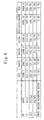
- the calculation results show that the diameter of the liquid side pipe (32) of R32 single refrigerant can be reduced about 0.76 times that of an R22 liquid side pipe. Further, the calculation results show that it is possible to reduce the diameter of the liquid side pipe (32) of R32/R125 mixed refrigerant about 0.76-0.8 times that of an R22 liquid side pipe if the R32 content is present in an amount of not less than 75 wt. %. The same calculations were performed on other replacement refrigerants for reference and the calculation results shows that none of them achieved better diameter reduction than the R32 (see Figure 6 ).
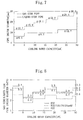
- Figure 7 is a diagram showing the pipe diameters (inside diameters) of gas side and liquid side pipes per cooling rated capacity in a conventional system using R22.
- the gas side pipe (31) is formed by use of a pipe having the same diameter as the aforesaid R22 gas side pipe, whereas the liquid side pipe (32) is formed by use of a pipe having a diameter smaller than that of the R22 liquid side pipe.
- the gas side pipe (31) and the liquid side pipe (32) having the following inside diameter ratios are used.
- the cooling rated capacity is greater than 5 kW but not more than 9 kW, such a combination of the gas side pipe (31) and the liquid side pipe (32) that the inside diameter ratio is in the range 2.1 to 3.5, is used. If the cooling rated capacity is not more than 5 kW or more than 9 kW, such a combination of the gas side pipe (31) and the liquid side pipe (32) that the inside diameter ratio is in the range 2.6 to 3.5, is used.
- the liquid side pipe (32) is formed by use of a pipe whose inside diameter is in the range of 3.2 mm to 4.2 mm. If the cooling rated capacity is greater than 5 kW but less than 22.4 kW, the liquid side pipe (32) is formed by use of a pipe whose inside diameter is in the range of 5.4 mm to 7.0 mm. If the cooling rated capacity is not less than 22.4 kW, the liquid side pipe (32) is formed by use of a pipe whose inside diameter is in the range of 7.5 mm to 9.8 mm.
- the inside diameter ratio or the inside diameter of the liquid side pipe (32) falls below the aforesaid numerical value range, there is a drop in the system performance, although the refrigerant charging amount is further reduced.
- the inside diameter ratio or the inside diameter of the liquid side pipe (32) exceeds the aforesaid numerical value range, the effect of reducing the charging amount of refrigerant diminishes, although the refrigerant pressure loss is reduced and the system performance is therefore improved.
- the inside diameters of the gas side pipe (31) and the liquid side pipe (32) are set to fall in the aforesaid numerical value ranges so that the refrigerant charging amount is sufficiently reduced while maintaining the system performance.
- the inside diameter ratio may be so restricted as to fall in the range of 2.4 to 3.2. If the cooling rated capacity is not more than 5 kW or more than 9 kW, the inside diameter ratio may be so restricted as to fall in the range of 2.8 to 3.3.
- the inside diameter ratio may be so restricted as to fall in the range from 2.6 to 3.0. If the cooling rated capacity is not more than 5 kW or more than 9 kW, the inside diameter ratio may be so restricted as to fall in the range of 2.9 to 3.1.
- the inside diameter of the liquid side pipe (32) may be so set as to fall in the range of 3.5 mm to 3.9 mm if the cooling rated capacity is not more than 5 kW. If the cooling rated capacity is greater than 5 kW but less than 22.4 kW, the inside diameter of the liquid side pipe (32) may be so set as to fall in the range of 5.7 mm to 6.7 mm. If the cooling rated capacity is not less than 22.4 kW, the inside diameter of the liquid side pipe (32) may be so set as to fall in the range of 7.8 mm to 9.5 mm.
- the inside diameter of the liquid side pipe (32) may be so set as to fall in the range of 3.6 mm to 3.8 mm if the cooling rated capacity is not more than 5 kW. If the cooling rated capacity is greater than 5 kW but less than 22.4 kW, the inside diameter of the liquid side pipe (32) may be so set as to fall in the range of 6.0 mm to 6.4 mm. If the cooling rated capacity is not less than 22.4 kW, the inside diameter of the liquid side pipe (32) may be so set as to fall in the range of 8.1 mm to 9.1 mm.
- both the liquid side pipe (32) and the gas side pipe (31) are preferably formed by combining only standardized articles so that the aforesaid inside diameter ratios are achieved.
- Figure 9 is a diagram for the purpose of comparing the specification of an R22 copper pipe (JISB8607) and that of an R32 high-pressure resistance pipe according to a proposal by Japanese Refrigeration Air Conditioning Industrial Association.
- a standardized pipe of ⁇ 8.0 mm can be used if R32 is used.
- the present embodiment is an embodiment capable of being implemented easily by combinations of standardized articles.
- the operation of the air conditioning system (1) will be described based on the refrigerant circulation operation of the refrigerant circuit (10).
- the four-way selector valve (12) is set as indicated by a solid line of Figure 1. That is, the four-way selector valve (12) is placed in such a state that the first port (12a) is brought into communication with the second port (12b) while the third port (12c) is brought into communication with the second port (12d).
- the two-phase refrigerant, after flowing out of the expansion valve (14 ) flows through the second liquid side pipe (26) .
- the two-phase refrigerant exchanges heat with indoor air in the indoor heat exchanger (15) and evaporates to change to gas refrigerant, whereby the indoor air is cooled.
- the gas refrigerant after flowing out of the indoor heat exchanger (15) , flows through the third gas side pipe (23) , the four-way selector valve (12) , and the fourth gas side pipe (24) and thereafter is drawn into the compressor (11) .
- the four-way selector valve (12) is set as indicated by a broken line of Figure 1 . That is, the four-way selector valve (12) is placed in such a state that the first port (12a) is brought into communication with the fourth port (12d) while the second port (12d) is brought into communication with the third port (12c) .
- the refrigerant, which has flowed into the indoor heat exchanger (15) exchanges heat with indoor air in the indoor heat exchanger (15) and condenses to change to liquid refrigerant, whereby the indoor air is heated.
- the liquid refrigerant, after flowing out of the indoor heat exchanger (15) flows through the second liquid side pipe (26) and is depressurized in the expansion valve (14) to change to gas-liquid two-phase refrigerant.
- the two-phase refrigerant after flowing out of the expansion valve (14) , flows through the first liquid side pipe (25) and evaporates to change to gas refrigerant in the outdoor heat exchanger (13) .
- the gas refrigerant after flowing out of the outdoor heat exchanger (13) , flows through the second gas side pipe (22) , the four-way selector valve (12) , and the fourth gas side pipe (24) and thereafter is drawn into the compressor (11) .
- either an R32 single refrigerant or an R32/R125 mixed refrigerant is used as a refrigerant and, in addition, the heat transfer pipes of the outdoor heat exchanger (13) and the indoor heat exchanger (15) and the liquid side pipe (32) each have a further reduction in diameter than conventional. Therefore, in accordance with the present embodiment, it is possible to reduce the internal volume of the refrigerant circuit (10) while maintaining the system performance, and it is possible to suppress contamination, e.g., moisture contamination and the like, which is introduced into the refrigerant circuit (10) .
- a synthetic oil as a refrigeration oil makes it possible to provide improvements in system reliability.
- circuit clogging due to the deposition of a sludge is unlikely to occur even when a synthetic oil is used as a refrigeration oil, thereby enhancing the reliability of the system.
- the possibility of the refrigerant circuit (10) being contaminated with air and other contaminants is small, this makes it possible to relax quality control procedures during manufacture and installation.
- the internal volume of the refrigerant circuit (10) becomes smaller, this makes it possible to reduce the amount of charging refrigerant. Therefore, the effect of global warming can be reduced. Further, by virtue of the reduction in heat transfer pipe diameter, the cost of the outdoor and indoor heat exchangers (13) and (15) can be lowered and the compacting of the outdoor and indoor heat exchangers (13) and (15) can be achieved. Therefore, it becomes possible to reduce the indoor unit (17) and the outdoor unit (16) in size.
- the gas side pipe (31) which is subjected to reduction in diameter may be all of the first gas side pipe (21) , the second gas side pipe (22) , the third gas side pipe (23) , and the fourth gas side pipe (24) or some of these gas side pipes.
- the liquid side pipe (32) which is subjected to reduction in diameter may be both the first liquid side pipe (25) and the second liquid side pipe (26) or one of these liquid side pipes.
- the diameter (inside or outside diameter) of the liquid side pipe (32) may be so set as to become smaller than them.
- the liquid side pipe (32) may be formed by use of a pipe whose diameter is less than 4.75 mm, when the cooling rated capacity is not more than 5 kW.
- liquid side pipe (32) may be formed by use of a pipe whose diameter is less than 7.92 mm, when the cooling rated capacity is greater than 5 kW but not more than 18 kW.
- liquid side pipe (32) may be formed by use of a pipe whose diameter is less than 11.1 mm, when the cooling rated capacity is greater than 18 kW but not more than 22.4 kW.
- liquid side pipe (32) may be formed by use of a pipe whose diameter is less than 13.88 mm, when the cooling rated capacity is greater than 22.4W.
- the diameter of the gas side pipe (31) may be so set as to become smaller than them.
- the gas side pipe (31 ) may be formed by use of a pipe whose diameter is less than 7.92 mm, when the cooling rated capacity is not more than 3.2 kW.
- gas side pipe (31) may be formed by use of a pipe whose diameter is less than 11.1 mm, when the cooling rated capacity is greater than 3.2 kW but not more than 5 kW.
- the gas side pipe (31) may be formed by use of a pipe whose diameter is less than 13.88 mm, when the cooling rated capacity is greater than 5 kW but not more than 9 kW.
- gas side pipe (31) may be formed by use of a pipe whose diameter is less than 17.05 mm, when the cooling rated capacity is greater than 9 kW but not more than 18 kW.
- gas side pipe (31) may be formed by use of a pipe whose diameter is less than 23.4 mm, when the cooling rated capacity is greater than 18 kW but not more than 22.4 kW.
- gas side pipe (31) may be formed by use of a pipe whose diameter is less than 26.18 mm, when the cooling rated capacity is greater than 22.4 kW.
- the diameter of the heat transfer pipe of each of the indoor heat exchanger (15) and the outdoor heat exchanger (13) may be so set as to become smaller than them.
- the heat transfer pipe of the indoor heat exchanger (15) may be formed by use of a pipe whose inside diameter is less than 5.87 mm.
- the heat transfer pipe of the outdoor heat exchanger (13) may be formed by use of a pipe whose inside diameter is less than 6.89 mm.
- the heat transfer pipe of the outdoor heat exchanger (13) may be formed by use of a pipe whose inside diameter is less than 7.99 mm.
- the above-described embodiment is intended for air conditioning systems of a so-called heat pump type capable of selectively performing cooling or heating mode operations.
- the applicability of the present invention is not limited to such a heat pump type air conditioning system.
- the present invention is applicable to cooling-only air conditioning systems.
- the present invention is made applicable to heating-only air conditioning systems by setting the inside diameter of both the liquid side pipe (32) and the gas side pipe (31) per heating rated capacity corresponding to a cooling rated capacity or by setting their inside diameter ratio.
- cooling rated capacity used in the aforesaid embodiment is meant an evaporator capacity.
- This cooling rated capacity is not limited to the capacity of an air conditioning system during cooling mode operations.
- the cooling rated capacity is a capacity which is exhibited under given JIS conditions (e.g., indoor dry-bulb temperature: 27 degrees Centigrade; outdoor wet-bulb temperature: 19 degrees Centigrade; and outdoor dry-bulb temperature: 35 degrees Centigrade) where the length of a connection pipe is 5 m and the difference in level between an indoor unit and an outdoor unit is 0 m.
- Neither the gas side pipe (31) nor the liquid side pipe (32) is necessarily formed by use of a copper pipe and these pipes may of course be formed of any other pipe such as a SUS pipe, an aluminum pipe, an iron pipe, or the like.
- the outdoor heat exchanger (13) and the indoor heat exchanger (13) are not limited to air heat exchangers and they may be liquid-liquid heat exchangers such as a heat exchanger of the double pipe type.
- the refrigeration system of the present invention is not limited to refrigeration systems in a restricted sense. That is, the refrigeration system of the present invention includes refrigeration systems in a wide sense such as a refrigerator and a dehumidifier, not to mention air conditioning systems.
- the present invention When the present invention is applied to a refrigeration system capable of accommodating long piping or to a refrigeration system provided with a plurality of indoor units, it is possible to extend the allowable length of piping. Furthermore, in accordance with the present invention, the number of indoor units can be increased. Accordingly, it becomes possible to provide improvements in system handling ease as well as in commodity property.
- the present invention When the present invention is applied to a machine capable of accommodating long piping or to a machine capable of accommodating a plurality of indoor units, it is possible to provide an extended allowable piping length. Furthermore, the present invention enables the number of indoor units to increase. Accordingly, it becomes possible to provide improvements in system handling ease as well as in commodity property.
- the refrigeration oil is not necessarily added with an extreme pressure additive.
- the refrigeration system of the present invention is useful for cases utilizing either an R32 single refrigerant or an R32/R125 mixed refrigerant, and the present invention is suitable particularly for a refrigeration system utilizing resin material.
Landscapes
- Engineering & Computer Science (AREA)
- Physics & Mathematics (AREA)
- Mechanical Engineering (AREA)
- Thermal Sciences (AREA)
- General Engineering & Computer Science (AREA)
- Chemical & Material Sciences (AREA)
- Chemical Kinetics & Catalysis (AREA)
- Combustion & Propulsion (AREA)
- Materials Engineering (AREA)
- Organic Chemistry (AREA)
- Compressor (AREA)
- Other Air-Conditioning Systems (AREA)
- Lubricants (AREA)
- Motor Or Generator Cooling System (AREA)
Abstract
A refrigerant circuit (10) is formed by connecting, in the order given, a
compressor (11), a four-way selector valve (12), an outdoor heat exchanger (13), an
expansion valve (14), and an indoor heat exchanger (15) by a gas side pipe (31) and a
liquid side pipe (32). The refrigerant circuit (10) is charged with a single refrigerant of
R32 or with an R32/R125 mixed refrigerant whose R32 content is not less than 75% by
weight. As an insulating material of an electric motor of the compressor (11), a resin
material is used, and as an refrigeration oil a synthetic oil is used. When cooling rated
capacity is not more than 5 kW, the liquid side pipe (32) is formed by use of a pipe
whose inside diameter is less than 4.75 mm.
Description
The present invention relates to refrigeration systems. More particularly, this
invention relates to a refrigeration system which employs either a single refrigerant of
R32 or an R32 containing mixed refrigerant.
A conventional refrigeration system has been known which comprises a
refrigerant circuit including a compressor, a condenser, a pressure reducing mechanism,
and an evaporator and the refrigerant circuit forms a refrigeration cycle using an HCFC
refrigerant such as R22. Of these element devices of the refrigerant circuit, the
compressor plays an important role of increasing the pressure of the refrigerant.
Therefore, refrigeration oil is required for smooth operation of the compressor.
On the other hand, refrigeration systems employing an HFC refrigerant use a
synthetic oil as a refrigeration oil.
However, such a synthetic oil is degraded when contaminated with air and
moisture, thereby causing a problem of increasing the total acid number of the synthetic
oil. On the other hand, resin materials have been utilized as an insulating material for
an electric motor of the compressor. However, the resin materials undergo deterioration
in strength (for example, deterioration in tensile strength) during the rise in total acid
number. This may cause burning out of the electric motor in the worst case.
Further, for the case of using a resin material such as polyethylene terephthalate
(PET), it is the resin material itself that causes hydrolysis during the rise in temperature
due to refrigeration operations, when coexisting with moisture. As a result, the
deterioration of the resin material will be aggravated.
Contamination with air and moisture occurs at the time of manufacture of the
element devices of the refrigerant circuit and at the time of installation of the system in
the field. Therefore, the amount of such contamination can be reduced by making a
change in the manufacture method and process and by reinforcing the product quality
control at the time of manufacture of the system. On the other hand, at the time of
installation of the system, it is necessary to take some measures for achieving
improvements in the degree of ultimate vacuum when drawing vacuum, for extending
the length of time taken to draw vacuum, and for providing improvements in vacuum
pump performance.
Therefore, with respect to refrigeration systems provided with a compressor, there
is the demand for further improvements in system reliability as well as in system
handling ease.
Bearing in mind the aforementioned problems, the present invention was made.
Accordingly, an object of the present invention is to provide improvements in system
reliability as well as in system handling ease.
With a view to achieving the aforesaid object, the present invention utilizes a resin
material as an insulating material for use in an electric motor of a compressor and
employs a refrigerant of less pressure loss (e.g., an R32 single refrigerant or R32 mixed
refrigerant) in comparison with the R22 or the like.
The present invention was made based on the following reasons. That is, by
reason of the fact that an R32 single refrigerant (or an R32 mixed refrigerant) provides a
greater refrigeration effect in comparison with R22, R407C, and R410A, less amounts
of circulating refrigerant necessary for obtaining the same capacity are required in
comparison with, for example, the R22. Therefore, for the case of the R32 single
refrigerant (or the R32 mixed refrigerant), its pressure loss is smaller in comparison
with, for example, the R22, when flowing through a flowpath of the same diameter.
The refrigerant pipe includes a liquid side pipe. The liquid side pipe is a pipe
extending, for example, from a condenser outlet to an evaporator inlet. The liquid side
pipe does not cause a drop in the system performance even when there is an increase in
the pressure loss, as long as that increase falls within the control range of the pressure
reducing mechanism (for example a capillary tube and an expansion valve). Further,
when employing an R32 single refrigerant or an R32 mixed refrigerant, the high-low
pressure difference in the refrigerant circuit is, at most, about 1.6 times greater than
when the R22 refrigerant is employed. Correspondingly, the allowable range for
refrigerant pressure loss extends. Accordingly, when the R32 single refrigerant (or the
R32 mixed refrigerant) is employed, it is possible to further reduce the diameter of the
liquid side pipe than conventional, without a drop in the system performance.
On the other hand, the refrigerant pipe further includes a discharge pipe and a
suction pipe. The discharge pipe is a pipe extending, for example, from a compressor
discharge side to a condenser inlet, whereas the suction pipe is a pipe extending, for
example, from an evaporator outlet to a compressor suction side. The pressure loss of
these discharge and suction pipes considerably affects the system performance.
However, the utilization of the R32 single refrigerant (or the R32 mixed refrigerant)
decreases the pressure loss to a further extent than conventional. This shows that, even
when the diameter of the discharge and suction pipes is reduced, the utilization of an
R32 single refrigerant (or an R32 mixed refrigerant) makes it possible to maintain the
same system performance as conventional. Furthermore, the R32 single refrigerant (or
the R32 mixed refrigerant) makes it possible to reduce the pipe diameter to some extent
while maintaining superiority in performance to conventional systems.
Further, as an element which affects the performance of a heat exchanger,
saturation temperature difference equivalent to the amount of refrigerant pressure loss
becomes important. For the case of the R32 single refrigerant (or the R32 mixed
refrigerant), the pressure loss is small. Therefore, even when the diameter of a heat
transfer pipe of the heat exchanger is reduced, the saturation temperature difference can
become the same as conventional. Furthermore, both the R32 single refrigerant and the
R32 mixed refrigerant have a higher heat transfer rate than conventional. Therefore,
even when a heat transfer pipe has a reduction in diameter, it is able to maintain the heat
exchanging capacity at high levels.
From the above, the inventor of the present invention found out that, even when
an R32 single refrigerant (or an R32 mixed refrigerant) is employed to reduce the
diameter of a refrigerant pipe and the diameter of a heat exchanger heat transfer pipe for
reducing the internal volume of a refrigerant circuit, there occurs no problem with the
system performance at all. On the other hand, the amount of air or moisture
contamination in a refrigerant circuit increases in proportion to the internal volume of a
refrigerant circuit. Therefore, in accordance with the present invention, the internal
volume of a refrigerant circuit is reduced by utilization of an R32 single refrigerant (or
an R32 mixed refrigerant) so that the amount of air or moisture contamination which is
introduced into the refrigerant circuit can be reduced, and the deterioration of an
insulating material used in an electric motor of the compressor is prevented.
HFC refrigeration systems employ a synthetic oil as a refrigeration oil. As a
synthetic oil, there are ether oil and ester oil having compatibility with refrigerant. And,
other than these synthetic oils, there is alkylbenzene oil which exhibits poor
compatibility with refrigerant but is able to secure the performance of returning oil by
viscosity reduction.
In comparison with mineral oil used in conventional R22 refrigeration systems,
the synthetic oil is more susceptible to chemical reaction such as decomposition,
polymerization and so forth, when the refrigerant circuit is contaminated with air or
moisture. As a result of this, part of the synthetic oil is deposited in the form of a sludge
in an expansion valve or in a capillary tube, which may cause clogging of a flowpath of
the refrigerant circuit.
More specifically, ether oil and alkylbenzene oil are susceptible to oxidative
deterioration by air and ester oil is hydrolyzed when contaminated with moisture. As a
result, the total acid number of each synthetic oil increases.
On the other hand, insulating material such as insulating paper, a lead wire, a
tying cord, or the like has been utilized for compressor electric motors. Such an
insulating material is a resin material. The insulating material is for example
polyethylene terephthalate (PET), polyethylene naphthalate (PEN), polyphenylene
sulfide (PPS), polybutylene terephthalate (PBT), polyether ether ketone (PEEK),
polyamide imide (PAI), or polyimide.
Any of these resin materials undergoes a drop in strength, e.g., a drop in tensile
strength, during the rise in total acid number. This may give rise to burning out of the
electric motor.
Further, for the case of PET, PEN, and PBT, their molecules contain therein ester
bonds. Because of this, when existing together with moisture, these resin materials
themselves cause hydrolysis during the rise in temperature by refrigeration operations.
As a result, the deterioration of the resin materials will be aggravated to a further extent.
Therefore, as described above, in the present invention an R32 single refrigerant
(or an R32 mixed refrigerant) is employed to reduce the internal volume of a refrigerant
circuit. Because of this, the amount of air or moisture contamination in the refrigerant
circuit can be reduced. Because of such a reduction in the amount of air or moisture
contamination, the deterioration of an insulating material for an electric motor of a
compressor can be prevented.
More specifically, in accordance with an invention of the present application,
either an R32 single refrigerant or a mixed refrigerant whose R32 content is not less
than 75% is employed and a resin material is utilized as an insulating material for an
electric motor in a compressor (11).
Another invention is directed to a refrigeration system whose cooling rated
capacity is not more than 5 kW, the refrigeration system comprising a refrigerant circuit
(10) which forms a refrigeration cycle in which either an R32 single refrigerant or a
mixed refrigerant whose R32 content is not less than 75% is used as a refrigerant and
includes a compressor (11) which utilizes a resin material as an electric motor insulating
material. And, the refrigerant circuit (10) includes a liquid side pipe (32) which is
formed by use of a pipe whose inside diameter is less than 4.75 mm.
Still another invention is directed to a refrigeration system whose cooling rated
capacity is not more than 5 kW, the refrigeration system comprising a refrigerant circuit
(10) which forms a refrigeration cycle in which either an R32 single refrigerant or a
mixed refrigerant whose R32 content is not less than 75% is used as a refrigerant and
includes a compressor (11) which utilizes a resin material as an electric motor insulating
material. And, the refrigerant circuit (10) includes a liquid side pipe (32) which is
formed by use of a pipe whose inside diameter ranges from 3.2 mm to 4.2 mm.
A further invention is directed to a refrigeration system whose cooling rated
capacity is not more than 5 kW, the refrigeration system comprising a refrigerant circuit
(10) which forms a refrigeration cycle in which either an R32 single refrigerant or a
mixed refrigerant whose R32 content is not less than 75% is used as a refrigerant and
includes a compressor (11) which utilizes a resin material as an electric motor insulating
material. And, the refrigerant circuit (10) includes a liquid side pipe (32) which is
formed by use of a pipe whose inside diameter ranges from 3.5 mm to 3.9 mm.
A still further invention is directed to a refrigeration system whose cooling rated
capacity is not more than 5 kW, the refrigeration system comprising a refrigerant circuit
(10) which forms a refrigeration cycle in which either an R32 single refrigerant or a
mixed refrigerant whose R32 content is not less than 75% is used as a refrigerant and
includes a compressor (11) which utilizes a resin material as an electric motor insulating
material. And, the refrigerant circuit (10) includes a liquid side pipe (32) which is
formed by use of a pipe whose inside diameter ranges from 3.6 mm to 3.8 mm.
Another invention is directed to a refrigeration system whose cooling rated
capacity is greater than 5 kW but not more than 18 kW, the refrigeration system
comprising a refrigerant circuit (10) which forms a refrigeration cycle in which either an
R32 single refrigerant or a mixed refrigerant whose R32 content is not less than 75% is
used as a refrigerant and includes a compressor (11) which utilizes a resin material as an
electric motor insulating material. And, the refrigerant circuit (10) includes a liquid side
pipe (32) which is formed by use of a pipe whose inside diameter is less than 7.92 mm.
Still another invention is directed to a refrigeration system whose cooling rated
capacity is greater than 18 kW but not more than 22.4 kW, the refrigeration system
comprising a refrigerant circuit (10) which forms a refrigeration cycle in which either an
R32 single refrigerant or a mixed refrigerant whose R32 content is not less than 75% is
used as a refrigerant and includes a compressor (11) which utilizes a resin material as an
electric motor insulating material. And, the refrigerant circuit (10) includes a liquid side
pipe (32) which is formed by use of a pipe whose inside diameter is less than 11.1 mm.
A further invention is directed to a refrigeration system whose cooling rated
capacity is greater than 5 kW but not more than 22.4 kW, the refrigeration system
comprising a refrigerant circuit (10) which forms a refrigeration cycle in which either an
R32 single refrigerant or a mixed refrigerant whose R32 content is not less than 75% is
used as a refrigerant and includes a compressor (11) which utilizes a resin material as an
electric motor insulating material. And, the refrigerant circuit (10) includes a liquid side
pipe (32) which is formed by use of a pipe whose inside diameter ranges from 5.4 mm
to 7.0 mm.
A still further invention is directed to a refrigeration system whose cooling rated
capacity is greater than 5 kW but not more than 22.4 kW, the refrigeration system
comprising a refrigerant circuit (10) which forms a refrigeration cycle in which either an
R32 single refrigerant or a mixed refrigerant whose R32 content is not less than 75% is
used as a refrigerant and includes a compressor (11) which utilizes a resin material as an
electric motor insulating material. And, the refrigerant circuit (10) includes a liquid side
pipe (32) which is formed by use of a pipe whose inside diameter ranges from 5.7 mm
to 6.7 mm.
Another invention is directed to a refrigeration system whose cooling rated
capacity is greater than 5 kW but not more than 22.4 kW, the refrigeration system
comprising a refrigerant circuit (10) which forms a refrigeration cycle in which either an
R32 single refrigerant or a mixed refrigerant whose R32 content is not less than 75% is
used as a refrigerant and includes a compressor (11) which utilizes a resin material as an
electric motor insulating material. And, the refrigerant circuit (10) includes a liquid side
pipe (32) which is formed by use of a pipe whose inside diameter ranges from 6.0 mm
to 6.4 mm.
Still another invention is directed to a refrigeration system whose cooling rated
capacity is so designed as to be greater than 22.4 kW, the refrigeration system
comprising a refrigerant circuit (10) which forms a refrigeration cycle in which either an
R32 single refrigerant or a mixed refrigerant whose R32 content is not less than 75% is
used as a refrigerant and includes a compressor (11) which utilizes a resin material as an
electric motor insulating material. And, the refrigerant circuit (10) includes a liquid side
pipe (32) which is formed by use of a pipe whose inside diameter is less than 13.88 mm.
A further invention is directed to a refrigeration system whose cooling rated
capacity is so designed as to be greater than 22.4 kW, the refrigeration system
comprising a refrigerant circuit (10) which forms a refrigeration cycle in which either an
R32 single refrigerant or a mixed refrigerant whose R32 content is not less than 75% is
used as a refrigerant and includes a compressor (11) which utilizes a resin material as an
electric motor insulating material. And, the refrigerant circuit (10) includes a liquid side
pipe (32) which is formed by use of a pipe whose inside diameter ranges from 7.5 mm
to 9.8 mm.
A still further invention is directed to a refrigeration system whose cooling rated
capacity is so designed as to be greater than 22.4 kW, the refrigeration system
comprising a refrigerant circuit (10) which forms a refrigeration cycle in which either an
R32 single refrigerant or a mixed refrigerant whose R32 content is not less than 75% is
used as a refrigerant and includes a compressor (11) which utilizes a resin material as an
electric motor insulating material. And, the refrigerant circuit (10) includes a liquid side
pipe (32) which is formed by use of a pipe whose inside diameter ranges from 7.8 mm
to 9.5 mm.
Another invention is directed to a refrigeration system whose cooling rated
capacity is so designed as to be greater than 22.4 kW, the refrigeration system
comprising a refrigerant circuit (10) which forms a refrigeration cycle in which either an
R32 single refrigerant or a mixed refrigerant whose R32 content is not less than 75% is
used as a refrigerant and includes a compressor (11) which utilizes a resin material as an
electric motor insulating material. And, the refrigerant circuit (10) includes a liquid side
pipe (32) which is formed by use of a pipe whose inside diameter ranges from 8.1 mm
to 9.1 mm.
Still another invention is directed to a refrigeration system whose cooling rated
capacity is not more than 3.2 kW, the refrigeration system comprising a refrigerant
circuit (10) which forms a refrigeration cycle in which either an R32 single refrigerant
or a mixed refrigerant whose R32 content is not less than 75% is used as a refrigerant
and includes a compressor (11) which utilizes a resin material as an electric motor
insulating material. And, the refrigerant circuit (10) includes a gas side pipe (31) which
is formed by use of a pipe whose inside diameter is less than 7.92 mm.
A further invention is directed to a refrigeration system whose cooling rated
capacity is greater than 3.2 kW but not more than 5 kW, the refrigeration system
comprising a refrigerant circuit (10) which forms a refrigeration cycle in which either an
R32 single refrigerant or a mixed refrigerant whose R32 content is not less than 75% is
used as a refrigerant and includes a compressor (11) which utilizes a resin material as an
electric motor insulating material. And, the refrigerant circuit (10) includes a gas side
pipe (31) which is formed by use of a pipe whose inside diameter is less than 11.1 mm.
A still further invention is directed to a refrigeration system whose cooling rated
capacity is greater than 5 kW but not more than 9 kW, the refrigeration system
comprising a refrigerant circuit (10) which forms a refrigeration cycle in which either an
R32 single refrigerant or a mixed refrigerant whose R32 content is not less than 75% is
used as a refrigerant and includes a compressor (11) which utilizes a resin material as an
electric motor insulating material. And, the refrigerant circuit (10) includes a gas side
pipe (31) which is formed by use of a pipe whose inside diameter is less than 13.88 mm.
Another invention is directed to a refrigeration system whose cooling rated
capacity is greater than 9 kW but not more than 18 kW, the refrigeration system
comprising a refrigerant circuit (10) which forms a refrigeration cycle in which either an
R32 single refrigerant or a mixed refrigerant whose R32 content is not less than 75% is
used as a refrigerant and includes a compressor (11) which utilizes a resin material as an
electric motor insulating material. And, the refrigerant circuit (10) includes a gas side
pipe (31) which is formed by use of a pipe whose inside diameter is less than 17.05 mm.
Still another invention is directed to a refrigeration system whose cooling rated
capacity is greater than 18 kW but not more than 22.4 kW, the refrigeration system
comprising a refrigerant circuit (10) which forms a refrigeration cycle in which either an
R32 single refrigerant or a mixed refrigerant whose R32 content is not less than 75% is
used as a refrigerant and includes a compressor (11) which utilizes a resin material as an
electric motor insulating material. And, the refrigerant circuit (10) includes a gas side
pipe (31) which is formed by use of a pipe whose inside diameter is less than 23.4 mm.
A further invention is directed to a refrigeration system whose cooling rated
capacity is so designed as to be greater than 22.4 kW, the refrigeration system
comprising a refrigerant circuit (10) which forms a refrigeration cycle in which either an
R32 single refrigerant or a mixed refrigerant whose R32 content is not less than 75% is
used as a refrigerant and includes a compressor (11) which utilizes a resin material as an
electric motor insulating material. And, the refrigerant circuit (10) includes a gas side
pipe (31) which is formed by use of a pipe whose inside diameter is less than 26.18 mm.
A still further invention is directed to a refrigeration system comprising a
refrigerant circuit (10) which includes (a) a compressor (11) which utilizes a resin
material as an electric motor insulating material and (b) an indoor heat exchanger (15)
and forms a refrigeration cycle in which either an R32 single refrigerant or a mixed
refrigerant whose R32 content is not less than 75% is used as a refrigerant. And, the
indoor heat exchanger (15) includes a heat transfer pipe which is formed by use of a
heat transfer pipe whose inside diameter is less than 5.87 mm.
Another invention is directed to a refrigeration system comprising a refrigerant
circuit (10) which includes (a) a compressor (11) which utilizes a resin material as an
electric motor insulating material and (b) an outdoor heat exchanger (13) and forms a
refrigeration cycle in which either an R32 single refrigerant or a mixed refrigerant
whose R32 content is not less than 75% is used as a refrigerant. And, the outdoor heat
exchanger (13) includes a heat transfer pipe which is formed by use of a heat transfer
pipe whose inside diameter is less than 6.89 mm.
Still another invention is directed to a refrigeration system comprising a
refrigerant circuit (10) which includes (a) a compressor (11) which utilizes a resin
material as an electric motor insulating material and (b) an outdoor heat exchanger (13)
and forms a refrigeration cycle in which either an R32 single refrigerant or a mixed
refrigerant whose R32 content is not less than 75% is used as a refrigerant. And, the
outdoor heat exchanger (13) includes a heat transfer pipe which is formed by use of a
heat transfer pipe whose inside diameter is less than 7.99 mm.
Further, the compressor (11) may use a synthetic oil as a refrigeration oil.
Furthermore, the liquid side pipe (32) may be a liquid side connecting pipe for
connecting an indoor unit (17) and an outdoor unit (16).
Further, the gas side pipe (31) may be a gas side connecting pipe for connecting
an indoor unit (17) and an outdoor unit (16).
Furthermore, preferably the mixed refrigerant is an R32/R125 mixed refrigerant.
Finally, the refrigerant may be an R32 single refrigerant.
Therefore, the present invention makes it possible to reduce the internal volume of
the refrigerant circuit (10), thereby making it possible to reduce the amount of air
contamination, moisture contamination, or other contamination which is introduced into
the refrigerant circuit (10). As a result, it is possible to prevent insulating materials used
in the electric motor in the compressor (11) from undergoing deterioration. Therefore,
burning out of the electric motor can be prevented and, in addition, a sliding portion of
the compressor (11) is prevented from undergoing abrasion and seizing. Further, the
expansion mechanism such as a capillary tube can be prevented from clogging, for
example. Accordingly, it is possible to achieve the reduction in fraction defective.
Furthermore, since the possibility that the refrigerant circuit (10) is contaminated
with air or other contaminants is small, this facilitates manufacture and install control,
thereby making it possible to provide improvements in manufacture ease and
installation ease.
Further, the use of a synthetic oil as a refrigeration oil makes it possible to provide
improvements in system reliability.
Hereinafter, embodiments of the present invention will be descried in conjunction
with the Figures.
As seen in Figure 1, a refrigeration system of the present embodiment is an air
conditioning system (1) formed by connection of an outdoor unit (16) which is a heat
source unit and an indoor unit (17) which is a utilization unit. A refrigerant circuit (10)
of the air conditioning system (1) employs, as its refrigerant, either a single refrigerant
of R32 (hereinafter referred to as the R32 single refrigerant) or a mixed refrigerant
comprising R32 and R125 in which the R32 content is not less than 75% but less than
100% by weight (i.e., an R32 composition rich mixed refrigerant which is hereinafter
called the R32/R125 mixed refrigerant).
The refrigerant circuit (10) is a refrigerant circuit which forms a vapor
compression refrigeration cycle. The refrigerant circuit (10) is formed by connecting, in
series in the order given, a compressor (11), a four-way selector valve (12), an outdoor
heat exchanger (13) which is a heat source side heat exchanger, an expansion valve (14)
which is an expansion mechanism, and an indoor heat exchanger (15) which is a
utilization side heat exchanger, by a gas side pipe (31) and a liquid side pipe (32).
These pipes (31) and (32) are refrigerant pipes.
More specifically, a discharge side of the compressor (11) and a first port (12a) of
the four-way selector valve (12) are connected together by a first gas side pipe (21). A
second port (12b) of the four-way selector valve (12) and the outdoor heat exchanger
(13) are connected together by a second gas side pipe (22). The outdoor heat exchanger
(13) and the expansion valve (14) are connected together by a first liquid side pipe (25).
The expansion valve (14) and the indoor heat exchanger (15) are connected together by
a second liquid side pipe (26). The indoor heat exchanger (15) and a third port (12c) of
the four-way selector valve (12) are connected together by a third gas side pipe (23). A
fourth port (12d) of the four-way selector valve (12) and a suction side of the
compressor (11) are connected together by a fourth gas side pipe (24).
The compressor (11), the first gas side pipe (21), the four-way selector valve (12),
the second gas side pipe (22), the outdoor heat exchanger (13), the first liquid side pipe
(25), the expansion valve (14), and the fourth gas side pipe (24) are all housed in an
outdoor unit (16), together with an outdoor air blower (not shown). On the other hand,
the indoor heat exchanger (15) is housed in an indoor unit (17), together with an indoor
air blower (not shown). A part of the second liquid side pipe (26) and a part of the third
gas side pipe (23) constitute a so-called connecting pipe for establishing connection
between the outdoor unit (16) and the indoor unit (17).
In the compressor (11), a synthetic oil is used as a refrigeration oil. Such a
synthetic oil comprises ether oil, ester oil, or the like. Other than these synthetic oils,
alkylbenzene oil may be used.
Further, the refrigeration oil is added with an extreme pressure additive. As an
extreme pressure additive, additives of the phosphorus family such as phosphoric ester
and phosphite may be used. Other than these phosphorus family additives, additives of
the chlorine family and additives of the sulfur family may be used.
On the other hand, an electric motor (not shown) of the compressor (11) is housed
in the casing. In the electric motor, insulating material such as insulating paper, a lead
wire, a tying cord and the like is used. Such an insulating material comprises a resin
material. And, the insulating material comprises polyethylene terephthalate (PET),
polyethylene naphthalate (PEN), polyphenylene sulfide (PPS), polybutylene
terephthalate (PBT), polyether ether ketone (PEEK), polyamide imide (PAI), polyimide,
or the like.
That is, the insulating paper, the lead wire, and the typing cord are formed by use
of these resin materials. For example, the insulating paper may be formed of PET and
the lead wire may be formed of PPS, and plural types of resin materials may be utilized
in the compressor electric motor.
Ether oil and alkylbenzene oil are susceptible to oxidative deterioration by air.
Ester oil is hydrolyzed by moisture contamination. As a result, the total acid number of
any of the synthetic oils increases.
Any of these resin materials undergoes a drop in strength such as a drop in tensile
strength during the rise in total acid number. This may give rise to burning out of the
electric motor in the worst case.
Further, for the case of PET, PEN, and PBT, their molecules contain therein ester
bonds. Because of this, when existing together with moisture, these resin materials
cause hydrolysis when the temperature rises by refrigeration operations. As a result, the
deterioration of the resin materials will be aggravated.
On the other hand, the refrigeration oil is added with an extreme pressure additive
for the prevention of abrasion and seizing of a sliding part of the compressor (11).
Particularly, since refrigerants of the HFC family such as R32 contain no chlorine atom,
there is no extreme pressure action. Therefore, an extreme pressure additive is added to
the refrigeration oil.
Such an extreme pressure additive is hydrolyzed when a sliding surface of the
compressor (11) is at high temperatures and when existing together with moisture and,
as a result, there is a drop in the lubricity. As a result, the extreme pressure additive
may be deposited in the form of a sludge in the expansion valve (14). Further, chlorine-family
extreme pressure additives may produce a corrosive substance.
Therefore, as will be described later, an R32 single refrigerant (or an R32/R125
mixed refrigerant) is used to diminish the internal volume of the refrigerant circuit (10),
for reducing the amount of air or moisture contamination.
Since the R32 single refrigerant (or the R32/R125 mixed refrigerant) exhibits a
greater refrigeration effect per unit volume than that of the R22, the former requires a
less amount of circulating refrigerant for achieving a specified capacity in comparison
with the later. Therefore, for the case of the R32 single refrigerant (or the R32/R125
mixed refrigerant), the amount of circulating refrigerant can be reduced, provided that
heat exchanger's heat transfer pipes of the same inside diameter are used. As a result,
the loss of tube pressure becomes smaller in comparison with the R22.
Generally, if the inside diameter of a heat transfer pipe of the heat exchanger is
made smaller, this results in a decrease in the heat transfer area and in an increase in the
refrigerant pressure loss, thereby causing a drop in the total system performance.
However, when using an R32 single refrigerant (or an R32/R125 mixed refrigerant), its
refrigerant side heat transfer rate in the heat transfer pipe is larger than that of R22, so
that it is possible to achieve the same total performance as R22 or a better total
performance than R22, even when the loss of tube pressure is increased up to about an
R22 equivalent level.
On the other hand, of all the devices of the refrigerant circuit (10), it is the outdoor
heat exchanger (13) which holds a largest amount of refrigerant. Accordingly, if the
diameter of the heat transfer pipe of the outdoor heat exchanger (13) is reduced, this
makes it possible to effectively reduce the amount of charging refrigerant. Further, such
a reduction in the heat transfer pipe diameter results in a decrease in the internal volume
of the refrigerant circuit (10). Furthermore, by virtue of the reduction of the heat
transfer pipe diameter, both the outdoor heat exchanger (13) and the indoor heat
exchanger (15) become smaller in size, thereby making it possible to promote the
compacting of the outdoor unit (16) and indoor unit (17).
Therefore, in the air conditioning system (1) of the present invention, the diameter
of the heat transfer pipes of the outdoor heat exchanger (13) and indoor heat exchanger
(15) is reduced to such an extent that the loss of tube pressure is at the same level as the
R22. More specifically, in the air conditioning system (1) of the present invention, the
amount of variation in the refrigerant saturation temperature corresponding to the
amount of pressure loss in the heat transfer pipe is taken into account and the inside
diameter dimension of the outdoor heat exchanger (13) and indoor heat exchanger (15)
is set so that the temperature variation amount becomes the same as that of the R22.
Next, a basic principle of constituting heat transfer pipes for the outdoor and
indoor heat exchangers (13) and (15) will be described in detail.
Here, as shown in Figure 2, each heat transfer pipe for the outdoor and indoor heat
exchangers (13) and (15) is set such that the saturation temperature variation ΔTe
corresponding to the pressure loss of evaporation refrigerant becomes the same as that
of R22 in a conventional system. That is,
ΔTe = Const.
Here,
The pressure loss ΔP is calculated using the following expression which is a
friction loss expression for annular pipes.
ΔP = λ·L/d·G2 /2·ρs·A2
If the cooling capacity Q = G × Δh is constant, then:
ΔP ∝ G2 /ρs·d5 ∝ (Δh2 ·ρs·d5 )-1
where Δh is the refrigeration effect (kJ/kg).
Therefore, the following expression is derived from the expressions (2) and (4).ΔTe ∝ {ΔT/ΔP} × (Δh2 ·ρs·d5 )-1
Therefore, the following expression is derived from the expressions (2) and (4).
Hence, from the expressions (1) and (5) and from the material property values of
R22 and R32, the inside diameter ratio of an R32 heat transfer pipe to an R22 heat
transfer pipe, i.e., the heat transfer pipe diameter reducing ratio, can be found by the
following expression.
{ΔT/ΔP}22 × (Δh22 2 ·ρs22 ·d22 5 )-1 = {ΔT/ΔP}32 × (Δh32 2 ·ρs32 ·d32 5 )-1
d32 /d22 = ((Δh32 /Δh22 )2 × ρs32 /ρs22 × ({ΔT/ΔP}32 /{ΔT/ΔP}22 )-1 )-1/5
Referring to Figure 3, there are shown results of calculations found by substitution
of each material property value into the expression (6). In the calculations, it is
assumed that the evaporation temperature Te is 2 degrees Centigrade and the
condensation temperature Tc is 49 degrees Centigrade, and the evaporator outlet super
heat SH = 5 degrees Centigrade and the condenser outlet sub cool SC = 5 degrees
Centigrade.
The calculation results show that the diameter of the R32 heat transfer pipe can be
reduced about 0.76 times that of the R22 heat transfer pipe. Further, the calculation
results show that the diameter of the R32/R125 heat transfer pipe can be reduced about
from 0.76 to 0.8 times that of the R22 heat transfer pipe. The same calculations were
performed on other replacement refrigerants for reference and the calculation results
show that none of them achieved better diameter reduction than the R32 (see Figure 3).
In the air conditioning system (1) of the present embodiment, based upon the
aforesaid principle, heat transfer pipes having the following inside diameters are
employed, for comparison with the R22 heat transfer pipe.
That is, when an R32 single refrigerant is used, the heat transfer pipe of the indoor
heat exchanger (15) is formed by use of a heat transfer pipe whose inside diameter is in
the range of 4.7 mm to 5.9 mm, whereas the heat transfer pipe of the outdoor heat
exchanger (13) is formed by use of a heat transfer pipe whose inside diameter is in the
range of 5.4 mm to 6.7 mm.
On the other hand, when an R32/R125 mixed refrigerant is used, the heat transfer
pipe of the indoor heat exchanger (15) is formed by use of a heat transfer pipe whose
inside diameter is in the range of 4.7 mm to 6.2 mm, whereas the heat transfer pipe of
the outdoor heat exchanger (13) is formed by use of a heat transfer pipe whose inside
diameter is in the range of 5.4 mm to 7.1 mm.
If the inside diameter of each heat transfer pipe falls below the numerical value
range, the loss of refrigerant pressure excessively increases, although the charging
amount of refrigerant is reduced further. On the other hand, the inside diameter of each
heat transfer pipe exceeds the numerical value range, the effect of R32 such as the effect
of reducing the amount of charging refrigerant is reduced, although the loss of
refrigerant pressure decreases and there is improvement in the system efficiency.
Therefore, in order to maintain a balance between them, in the present
embodiment the inside diameters of the heat transfer pipes of the outdoor and indoor
heat exchangers (13) and (15) are so set as to fall in the aforesaid numerical value
ranges.
Of course, there may be made further restrictions on the numerical value ranges
for allowing R32 to exhibit its characteristics more significantly, depending upon the
system use condition or other condition.
For example, when an R32 single refrigerant is used, the heat transfer pipe of the
indoor heat exchanger (15) may be formed by use of a heat transfer pipe whose inside
diameter is in the range of 4.9 mm to 5.7 mm, whereas the heat transfer pipe of the
outdoor heat exchanger (13) may be formed by use of a heat transfer pipe whose inside
diameter is in the range of 5.6 mm to 6.5 mm.
Further, when an R32 single refrigerant is used, the heat transfer pipe of the
indoor heat exchanger (15) may be formed by use of a heat transfer pipe whose inside
diameter is in the range of 5.1 mm to 5.5 mm, whereas the heat transfer pipe of the
outdoor heat exchanger (13) may be formed by use of a heat transfer pipe whose inside
diameter is in the range of 5.8 mm to 6.3 mm.
On the other hand, when an R32/R125 mixed refrigerant is used, the heat transfer
pipe of the indoor heat exchanger (15) may be formed by use of a heat transfer pipe
whose inside diameter is in the range of 4.9 mm to 6.0 mm, whereas the heat transfer
pipe of the outdoor heat exchanger (13) may be formed by use of a heat transfer pipe
whose inside diameter is in the range of 5.6 mm to 6.9 mm.
Further, when an R32/R125 mixed refrigerant is used, the heat transfer pipe of the
indoor heat exchanger (15) may be formed by use of a heat transfer pipe whose inside
diameter is in the range of 5.2 mm to 5.7 mm, whereas the heat transfer pipe of the
outdoor heat exchanger (13) may be formed by use of a heat transfer pipe whose inside
diameter is in the range of 5.9 mm to 6.6 mm.
Here, by "the inside diameter of a heat transfer pipe" for the case of internal side
smoothed pipes is meant a pipe inside diameter after pipe expansion. Further, as shown
in Figure 4, by "the inside diameter of a heat transfer pipe" for the case of internal side
grooved pipes is meant a value which is a remainder of subtracting from the outside
diameter after pipe expansion a value which is twice the bottom thickness, i.e., the
inside diameter di = do - 2t.
Various heat transfer pipes, such as a pipe made of copper or aluminum, are
available. The outdoor and indoor heat exchangers (13) and (15) of the present
embodiment are each formed by a plate fin tube heat exchanger comprising a copper
pipe and an aluminum fin as an air heat exchanger capable of exchanging heat with air.
Therefore, their heat transfer pipes are each formed by use of a copper pipe.
Further, in the air conditioning system (1) of the present embodiment, not only the
diameter of the heat transfer pipes of the heat exchangers (13, 15) but also the diameter
of the refrigerant pipe of the refrigerant circuit (10) is reduced in order that the internal
volume of the refrigerant circuit (10) may be reduced.
As described above, if an R32 single refrigerant (or an R32/R125 mixed
refrigerant) is used intact in an existing R22 refrigerant pipe, the loss of refrigerant
pressure is reduced. Therefore, even if the inside diameter of the liquid side pipe (32) of
the refrigerant circuit (10) is reduced for increasing the loss of tube pressure to the same
level as the time that R22 is used, this maintains the system performance at the same
level as conventional. Therefore, in the air conditioning system (1), the liquid side pipe
(32) has a reduction in diameter to such an extent that the loss of pipe pressure becomes
equivalent to that of R22, for reducing the internal volume of the refrigerant circuit (10)
while maintaining the system performance.
On the other hand, in the present embodiment, the gas side pipe (31) is the same
as a commonly-used R22 gas side pipe. However, in order to provide a reduction in
diameter of the gas side pipe (31), it is more preferable that the diameter of the liquid
side pipe (32) also be reduced.
Next, a basic principle of constructing the liquid side pipe (32) will be described.
Here, the liquid side pipe (32) is designed such that the ratio of the pressure loss
of the liquid side pipe (32) to the amount of drop in the pressure of refrigerant from the
condenser outlet to the evaporator inlet is the same as the case of R22. That is, the
following expression, in which the signs shown in Figure 5 are used, holds as follows.
(Pco - Pvi) + (Pvo - Pbi)/(Pco - Pei) = Const.
where:
Here, the capacity Q = G × Δh is constant and the following expression is derived
from the expression (8).
ΔP ∝ G2 /ρs·d5 ∝ (Δh2 ·ρs·d5 )-1
where:
Therefore, the following expression is derived.
(Pco - Pvi) + (Pvo - Pbi) ∝ (Δh2 ·ρs·d5 )-1
And, the following expression is derived from the expressions (7) and (10).
(Pco - Pvi) + (Pvo - Pbi)/(Pco - Pei) ∝ (Δh2 ·ρs·d5 )-1 /(HP - LP)
Therefore, from the expressions (7) and (11) and from the material property
values of R22 and R32, the heat transfer pipe diameter reducing ratio of an R32 heat
transfer pipe to an R22 heat transfer pipe can be found by the following expression.
(Δh22 2 ·ρs22 ·d22 5 )-1 /(HP22 -LP22 ) = (Δh32 2 ·ρs32 ·d32 5 )-1 /(HP32 - LP32 )
d32 /d22 = ((Δh32 /Δh22 )2 × ρs32 /ρs22 × (HP32 - LP32 )/(HP22 -LP22 )-1/5
Referring to Figure 6, there are shown results of calculations found by substitution
of each material property value into the expression (12). Also in these calculations, the
evaporation temperature Te is 2 degrees Centigrade and the condensation temperature
Tc is 49 degrees Centigrade, and the super heat SH = 5 degrees Centigrade and the sub
cool SC = 5 degrees Centigrade.
The calculation results show that the diameter of the liquid side pipe (32) of R32
single refrigerant can be reduced about 0.76 times that of an R22 liquid side pipe.
Further, the calculation results show that it is possible to reduce the diameter of the
liquid side pipe (32) of R32/R125 mixed refrigerant about 0.76-0.8 times that of an R22
liquid side pipe if the R32 content is present in an amount of not less than 75 wt. %.
The same calculations were performed on other replacement refrigerants for reference
and the calculation results shows that none of them achieved better diameter reduction
than the R32 (see Figure 6).
Figure 7 is a diagram showing the pipe diameters (inside diameters) of gas side
and liquid side pipes per cooling rated capacity in a conventional system using R22.
In the air conditioning system (1) of the present embodiment, according to the
cooling rated capacity, the gas side pipe (31) is formed by use of a pipe having the same
diameter as the aforesaid R22 gas side pipe, whereas the liquid side pipe (32) is formed
by use of a pipe having a diameter smaller than that of the R22 liquid side pipe.
Figure 8 is a diagram showing the ratio of the inside diameter dg of a gas side
pipe to the inside diameter dl of a liquid side pipe, i.e., the inside diameter ratio (= the
gas side pipe inside diameter dg/the liquid side pipe inside diameter dl). In the air
conditioning system (1) of the present embodiment, according to the cooling rated
capacity, the gas side pipe (31) and the liquid side pipe (32) having the following inside
diameter ratios are used.
That is, if the cooling rated capacity is greater than 5 kW but not more than 9 kW,
such a combination of the gas side pipe (31) and the liquid side pipe (32) that the inside
diameter ratio is in the range 2.1 to 3.5, is used. If the cooling rated capacity is not
more than 5 kW or more than 9 kW, such a combination of the gas side pipe (31) and
the liquid side pipe (32) that the inside diameter ratio is in the range 2.6 to 3.5, is used.
Further, if the cooling rated capacity is not more than 5 kW, the liquid side pipe
(32) is formed by use of a pipe whose inside diameter is in the range of 3.2 mm to 4.2
mm. If the cooling rated capacity is greater than 5 kW but less than 22.4 kW, the liquid
side pipe (32) is formed by use of a pipe whose inside diameter is in the range of 5.4
mm to 7.0 mm. If the cooling rated capacity is not less than 22.4 kW, the liquid side
pipe (32) is formed by use of a pipe whose inside diameter is in the range of 7.5 mm to
9.8 mm.
If the inside diameter ratio or the inside diameter of the liquid side pipe (32) falls
below the aforesaid numerical value range, there is a drop in the system performance,
although the refrigerant charging amount is further reduced. On the other hand, the
inside diameter ratio or the inside diameter of the liquid side pipe (32) exceeds the
aforesaid numerical value range, the effect of reducing the charging amount of
refrigerant diminishes, although the refrigerant pressure loss is reduced and the system
performance is therefore improved.
To cope with the above problem, in the present embodiment the inside diameters
of the gas side pipe (31) and the liquid side pipe (32) are set to fall in the aforesaid
numerical value ranges so that the refrigerant charging amount is sufficiently reduced
while maintaining the system performance.
Of course, there may be made further restrictions on the numerical value ranges,
depending upon the system use condition or other conditions.
For example, if the cooling rated capacity is greater than 5 kW but not more than
9 kW, the inside diameter ratio may be so restricted as to fall in the range of 2.4 to 3.2.
If the cooling rated capacity is not more than 5 kW or more than 9 kW, the inside
diameter ratio may be so restricted as to fall in the range of 2.8 to 3.3.
Further, if the cooling rated capacity is greater than 5 kW but not more than 9 kW,
the inside diameter ratio may be so restricted as to fall in the range from 2.6 to 3.0. If
the cooling rated capacity is not more than 5 kW or more than 9 kW, the inside diameter
ratio may be so restricted as to fall in the range of 2.9 to 3.1.
Further, the inside diameter of the liquid side pipe (32) may be so set as to fall in
the range of 3.5 mm to 3.9 mm if the cooling rated capacity is not more than 5 kW. If
the cooling rated capacity is greater than 5 kW but less than 22.4 kW, the inside
diameter of the liquid side pipe (32) may be so set as to fall in the range of 5.7 mm to
6.7 mm. If the cooling rated capacity is not less than 22.4 kW, the inside diameter of
the liquid side pipe (32) may be so set as to fall in the range of 7.8 mm to 9.5 mm.
Further, the inside diameter of the liquid side pipe (32) may be so set as to fall in
the range of 3.6 mm to 3.8 mm if the cooling rated capacity is not more than 5 kW. If
the cooling rated capacity is greater than 5 kW but less than 22.4 kW, the inside
diameter of the liquid side pipe (32) may be so set as to fall in the range of 6.0 mm to
6.4 mm. If the cooling rated capacity is not less than 22.4 kW, the inside diameter of
the liquid side pipe (32) may be so set as to fall in the range of 8.1 mm to 9.1 mm.
Copper pipes have been used as a refrigerant pipe in many cases because they are
inexpensive and easy to handle. Since various standardized copper pipes are available,
it is possible to reduce the cost of the refrigerant pipes (31, 32) by utilizing existing
standardized articles. Accordingly, for the purpose of reducing the system cost, both
the liquid side pipe (32) and the gas side pipe (31) are preferably formed by combining
only standardized articles so that the aforesaid inside diameter ratios are achieved.
Figure 9 is a diagram for the purpose of comparing the specification of an R22
copper pipe (JISB8607) and that of an R32 high-pressure resistance pipe according to a
proposal by Japanese Refrigeration Air Conditioning Industrial Association.
For the case of the R32 single refrigerant, its best inside diameter ratio calculated
from the aforesaid calculation results is 0.76, whereas, for the case of the R32/R125
mixed refrigerant whose R32 content is 75 wt. %, its best inside diameter ratio is 0.80.
Figure 9 shows that the inside diameter ratios can be realized easily by combinations of
standardized articles, if within ± 10% of the best inside diameter ratios.
For example, instead of using an R22 standardized pipe of 9.5 mm, a
standardized pipe of 8.0 mm can be used if R32 is used. The present embodiment is an
embodiment capable of being implemented easily by combinations of standardized
articles.
The operation of the air conditioning system (1) will be described based on the
refrigerant circulation operation of the refrigerant circuit (10).
During cooling mode operations, the four-way selector valve (12) is set as
indicated by a solid line of Figure 1. That is, the four-way selector valve (12) is placed
in such a state that the first port (12a) is brought into communication with the second
port (12b) while the third port (12c) is brought into communication with the second port
(12d).
In such a state, gas refrigerant discharged out of the compressor (11), after
flowing through the first gas side pipe (21), the four-way selector valve (12), and the
second gas side pipe (22), condenses to change to liquid refrigerant in the outdoor heat
exchanger (13). The liquid refrigerant, after flowing out of the outdoor heat exchanger
(13), flows through the first liquid side pipe (25) and is depressurized in the expansion
valve (14) to change to gas-liquid two-phase refrigerant. The two-phase refrigerant,
after flowing out of the expansion valve (14), flows through the second liquid side pipe
(26). Thereafter, the two-phase refrigerant exchanges heat with indoor air in the indoor
heat exchanger (15) and evaporates to change to gas refrigerant, whereby the indoor air
is cooled. The gas refrigerant, after flowing out of the indoor heat exchanger (15),
flows through the third gas side pipe (23), the four-way selector valve (12), and the
fourth gas side pipe (24) and thereafter is drawn into the compressor (11).
On the other hand, during heating mode operations, the four-way selector valve
(12) is set as indicated by a broken line of Figure 1. That is, the four-way selector valve
(12) is placed in such a state that the first port (12a) is brought into communication with
the fourth port (12d) while the second port (12d) is brought into communication with
the third port (12c).
In such a state, gas refrigerant discharged out of the compressor (11), after
flowing through the first gas side pipe (21), the four-way selector valve (12), and the
third gas side pipe (23), enters the indoor heat exchanger (15). The refrigerant, which
has flowed into the indoor heat exchanger (15), exchanges heat with indoor air in the
indoor heat exchanger (15) and condenses to change to liquid refrigerant, whereby the
indoor air is heated. The liquid refrigerant, after flowing out of the indoor heat
exchanger (15), flows through the second liquid side pipe (26) and is depressurized in
the expansion valve (14) to change to gas-liquid two-phase refrigerant. The two-phase
refrigerant, after flowing out of the expansion valve (14), flows through the first liquid
side pipe (25) and evaporates to change to gas refrigerant in the outdoor heat exchanger
(13). The gas refrigerant, after flowing out of the outdoor heat exchanger (13), flows
through the second gas side pipe (22), the four-way selector valve (12), and the fourth
gas side pipe (24) and thereafter is drawn into the compressor (11).
As described above, in the present embodiment, either an R32 single refrigerant or
an R32/R125 mixed refrigerant is used as a refrigerant and, in addition, the heat transfer
pipes of the outdoor heat exchanger (13) and the indoor heat exchanger (15) and the
liquid side pipe (32) each have a further reduction in diameter than conventional.
Therefore, in accordance with the present embodiment, it is possible to reduce the
internal volume of the refrigerant circuit (10) while maintaining the system performance,
and it is possible to suppress contamination, e.g., moisture contamination and the like,
which is introduced into the refrigerant circuit (10).
As a result of the above arrangement, it is possible to prevent the deterioration of
insulating materials used in the electric motor of the compressor (11). This makes it
possible to prevent the electric motor from burning out and to prevent a sliding section
of the compressor (11) from undergoing abrasion and seizing. Further, the expansion
valve (14) can be prevented from undergoing clogging or the like. Accordingly, it is
possible to achieve a reduction in the fraction defective.
Furthermore, since the possibility that the refrigerant circuit (10) is contaminated
with air and other contaminants is small, this facilitates manufacture and install control
of the system, thereby making it possible to provide improvements in manufacture ease
and installation ease.
Further, the use of a synthetic oil as a refrigeration oil makes it possible to provide
improvements in system reliability. In other words, circuit clogging due to the
deposition of a sludge is unlikely to occur even when a synthetic oil is used as a
refrigeration oil, thereby enhancing the reliability of the system. Furthermore, since the
possibility of the refrigerant circuit (10) being contaminated with air and other
contaminants is small, this makes it possible to relax quality control procedures during
manufacture and installation.
Further, since the internal volume of the refrigerant circuit (10) becomes smaller,
this makes it possible to reduce the amount of charging refrigerant. Therefore, the
effect of global warming can be reduced. Further, by virtue of the reduction in heat
transfer pipe diameter, the cost of the outdoor and indoor heat exchangers (13) and (15)
can be lowered and the compacting of the outdoor and indoor heat exchangers (13) and
(15) can be achieved. Therefore, it becomes possible to reduce the indoor unit (17) and
the outdoor unit (16) in size.
Furthermore, since the possibility of the refrigerant circuit (10) being
contaminated with moisture or other contaminants is small, this prevents an extreme
pressure additive added to a refrigeration oil from being hydrolyzed and prevents a drop
in the lubricity. Especially, deteriorated substances hydrolyzed will not be deposited in
the form of a sludge, thereby preventing the flowpath of the refrigerant circuit from
being clogged, without fail.
Further, it is possible to prevent generation of corrosive substances, such as
hydrochloric acid, in an extreme pressure additive of the chlorine family.
In accordance with the present invention, it is, of course, possible to obtain an
effect of reducing the internal volume of the refrigerant circuit (10) by reducing the
diameter of both the gas side pipe (31) and the liquid side pipe (32). However, such an
effect can be obtained by reducing only the diameter of the gas side pipe (31).
The gas side pipe (31) which is subjected to reduction in diameter may be all of
the first gas side pipe (21), the second gas side pipe (22), the third gas side pipe (23),
and the fourth gas side pipe (24) or some of these gas side pipes. Likewise, the liquid
side pipe (32) which is subjected to reduction in diameter may be both the first liquid
side pipe (25) and the second liquid side pipe (26) or one of these liquid side pipes.
On the basis of R22 liquid side pipe values different from those shown in Figure 7,
the diameter (inside or outside diameter) of the liquid side pipe (32) may be so set as to
become smaller than them.
More specifically, the liquid side pipe (32) may be formed by use of a pipe whose
diameter is less than 4.75 mm, when the cooling rated capacity is not more than 5 kW.
Further, the liquid side pipe (32) may be formed by use of a pipe whose diameter
is less than 7.92 mm, when the cooling rated capacity is greater than 5 kW but not more
than 18 kW.
Further, the liquid side pipe (32) may be formed by use of a pipe whose diameter
is less than 11.1 mm, when the cooling rated capacity is greater than 18 kW but not
more than 22.4 kW.
Further, the liquid side pipe (32) may be formed by use of a pipe whose diameter
is less than 13.88 mm, when the cooling rated capacity is greater than 22.4W.
On the basis of R22 gas side pipe values different from those shown in Figure 7,
the diameter of the gas side pipe (31) may be so set as to become smaller than them.
More specifically, the gas side pipe (31) may be formed by use of a pipe whose
diameter is less than 7.92 mm, when the cooling rated capacity is not more than 3.2 kW.
Further, the gas side pipe (31) may be formed by use of a pipe whose diameter is
less than 11.1 mm, when the cooling rated capacity is greater than 3.2 kW but not more
than 5 kW.
Further, the gas side pipe (31) may be formed by use of a pipe whose diameter is
less than 13.88 mm, when the cooling rated capacity is greater than 5 kW but not more
than 9 kW.
Further, the gas side pipe (31) may be formed by use of a pipe whose diameter is
less than 17.05 mm, when the cooling rated capacity is greater than 9 kW but not more
than 18 kW.
Further, the gas side pipe (31) may be formed by use of a pipe whose diameter is
less than 23.4 mm, when the cooling rated capacity is greater than 18 kW but not more
than 22.4 kW.
Further, the gas side pipe (31) may be formed by use of a pipe whose diameter is
less than 26.18 mm, when the cooling rated capacity is greater than 22.4 kW.
On the basis of R22 heat transfer pipe values, the diameter of the heat transfer
pipe of each of the indoor heat exchanger (15) and the outdoor heat exchanger (13) may
be so set as to become smaller than them.
More specifically, the heat transfer pipe of the indoor heat exchanger (15) may be
formed by use of a pipe whose inside diameter is less than 5.87 mm.
Further, the heat transfer pipe of the outdoor heat exchanger (13) may be formed
by use of a pipe whose inside diameter is less than 6.89 mm.
Further, the heat transfer pipe of the outdoor heat exchanger (13) may be formed
by use of a pipe whose inside diameter is less than 7.99 mm.
The above-described embodiment is intended for air conditioning systems of a so-called
heat pump type capable of selectively performing cooling or heating mode
operations. However, the applicability of the present invention is not limited to such a
heat pump type air conditioning system. For example, the present invention is
applicable to cooling-only air conditioning systems. Further, the present invention is
made applicable to heating-only air conditioning systems by setting the inside diameter
of both the liquid side pipe (32) and the gas side pipe (31) per heating rated capacity
corresponding to a cooling rated capacity or by setting their inside diameter ratio.
Further, by "cooling rated capacity" used in the aforesaid embodiment is meant an
evaporator capacity. This cooling rated capacity is not limited to the capacity of an air
conditioning system during cooling mode operations. The cooling rated capacity is a
capacity which is exhibited under given JIS conditions (e.g., indoor dry-bulb
temperature: 27 degrees Centigrade; outdoor wet-bulb temperature: 19 degrees
Centigrade; and outdoor dry-bulb temperature: 35 degrees Centigrade) where the length
of a connection pipe is 5 m and the difference in level between an indoor unit and an
outdoor unit is 0 m.
Neither the gas side pipe (31) nor the liquid side pipe (32) is necessarily formed
by use of a copper pipe and these pipes may of course be formed of any other pipe such
as a SUS pipe, an aluminum pipe, an iron pipe, or the like.
The outdoor heat exchanger (13) and the indoor heat exchanger (13) are not
limited to air heat exchangers and they may be liquid-liquid heat exchangers such as a
heat exchanger of the double pipe type.
The refrigeration system of the present invention is not limited to refrigeration
systems in a restricted sense. That is, the refrigeration system of the present invention
includes refrigeration systems in a wide sense such as a refrigerator and a dehumidifier,
not to mention air conditioning systems.
When the present invention is applied to a refrigeration system capable of
accommodating long piping or to a refrigeration system provided with a plurality of
indoor units, it is possible to extend the allowable length of piping. Furthermore, in
accordance with the present invention, the number of indoor units can be increased.
Accordingly, it becomes possible to provide improvements in system handling ease as
well as in commodity property.
When the present invention is applied to a machine capable of accommodating
long piping or to a machine capable of accommodating a plurality of indoor units, it is
possible to provide an extended allowable piping length. Furthermore, the present
invention enables the number of indoor units to increase. Accordingly, it becomes
possible to provide improvements in system handling ease as well as in commodity
property.
Further, in the present invention, the refrigeration oil is not necessarily added with
an extreme pressure additive.
As has been described above, the refrigeration system of the present invention is
useful for cases utilizing either an R32 single refrigerant or an R32/R125 mixed
refrigerant, and the present invention is suitable particularly for a refrigeration system
utilizing resin material.
Claims (28)
- A refrigeration system which employs either a single refrigerant of R32 or a mixed refrigerant whose R32 content is not less than 75% and utilizes a resin material as an insulating material for an electric motor in a compressor (11).
- A refrigeration system whose cooling rated capacity is not more than 5 kW, said refrigeration system comprising a refrigerant circuit (10) which forms a refrigeration cycle in which either a single refrigerant of R32 or a mixed refrigerant whose R32 content is not less than 75% is used as a refrigerant and includes a compressor (11) which utilizes a resin material as an electric motor insulating material,
wherein said refrigerant circuit (10) includes a liquid side pipe (32) which is formed by use of a pipe whose inside diameter is less than 4.75 mm. - A refrigeration system whose cooling rated capacity is not more than 5 kW, said refrigeration system comprising a refrigerant circuit (10) which forms a refrigeration cycle in which either a single refrigerant of R32 or a mixed refrigerant whose R32 content is not less than 75% is used as a refrigerant and includes a compressor (11) which utilizes a resin material as an electric motor insulating material,
wherein said refrigerant circuit (10) includes a liquid side pipe (32) which is formed by use of a pipe whose inside diameter ranges from 3.2 mm to 4.2 mm. - A refrigeration system whose cooling rated capacity is not more than 5 kW, said refrigeration system comprising a refrigerant circuit (10) which forms a refrigeration cycle in which either a single refrigerant of R32 or a mixed refrigerant whose R32 content is not less than 75% is used as a refrigerant and includes a compressor (11) which utilizes a resin material as an electric motor insulating material,
wherein said refrigerant circuit (10) includes a liquid side pipe (32) which is formed by use of a pipe whose inside diameter ranges from 3.5 mm to 3.9 mm. - A refrigeration system whose cooling rated capacity is not more than 5 kW, said refrigeration system comprising a refrigerant circuit (10) which forms a refrigeration cycle in which either a single refrigerant of R32 or a mixed refrigerant whose R32 content is not less than 75% is used as a refrigerant and includes a compressor (11) which utilizes a resin material as an electric motor insulating material,
wherein said refrigerant circuit (10) includes a liquid side pipe (32) which is formed by use of a pipe whose inside diameter ranges from 3.6 mm to 3.8 mm. - A refrigeration system whose cooling rated capacity is greater than 5 kW but not more than 18 kW, said refrigeration system comprising a refrigerant circuit (10) which forms a refrigeration cycle in which either a single refrigerant of R32 or a mixed refrigerant whose R32 content is not less than 75% is used as a refrigerant and includes a compressor (11) which utilizes a resin material as an electric motor insulating material,
wherein said refrigerant circuit (10) includes a liquid side pipe (32) which is formed by use of a pipe whose inside diameter is less than 7.92 mm. - A refrigeration system whose cooling rated capacity is greater than 18 kW but not more than 22.4 kW, said refrigeration system comprising a refrigerant circuit (10) which forms a refrigeration cycle in which either a single refrigerant of R32 or a mixed refrigerant whose R32 content is not less than 75% is used as a refrigerant and includes a compressor (11) which utilizes a resin material as an electric motor insulating material,
wherein said refrigerant circuit (10) includes a liquid side pipe (32) which is formed by use of a pipe whose inside diameter is less than 11.1 mm. - A refrigeration system whose cooling rated capacity is greater than 5 kW but not more than 22.4 kW, said refrigeration system comprising a refrigerant circuit (10) which forms a refrigeration cycle in which either a single refrigerant of R32 or a mixed refrigerant whose R32 content is not less than 75% is used as a refrigerant and includes a compressor (11) which utilizes a resin material as an electric motor insulating material,
wherein said refrigerant circuit (10) includes a liquid side pipe (32) which is formed by use of a pipe whose inside diameter ranges from 5.4 mm to 7.0 mm. - A refrigeration system whose cooling rated capacity is greater than 5 kW but not more than 22.4 kW, said refrigeration system comprising a refrigerant circuit (10) which forms a refrigeration cycle in which either a single refrigerant of R32 or a mixed refrigerant whose R32 content is not less than 75% is used as a refrigerant and includes a compressor (11) which utilizes a resin material as an electric motor insulating material,
wherein said refrigerant circuit (10) includes a liquid side pipe (32) which is formed by use of a pipe whose inside diameter ranges from 5.7 mm to 6.7 mm. - A refrigeration system whose cooling rated capacity is greater than 5 kW but not more than 22.4 kW, said refrigeration system comprising a refrigerant circuit (10) which forms a refrigeration cycle in which either a single refrigerant of R32 or a mixed refrigerant whose R32 content is not less than 75% is used as a refrigerant and includes a compressor (11) which utilizes a resin material as an electric motor insulating material,
wherein said refrigerant circuit (10) includes a liquid side pipe (32) which is formed by use of a pipe whose inside diameter ranges from 6.0 mm to 6.4 mm. - A refrigeration system whose cooling rated capacity is so designed as to be greater than 22.4 kW, said refrigeration system comprising a refrigerant circuit (10) which forms a refrigeration cycle in which either a single refrigerant of R32 or a mixed refrigerant whose R32 content is not less than 75% is used as a refrigerant and includes a compressor (11) which utilizes a resin material as an electric motor insulating material,
wherein said refrigerant circuit (10) includes a liquid side pipe (32) which is formed by use of a pipe whose inside diameter is less than 13.88 mm. - A refrigeration system whose cooling rated capacity is so designed as to be greater than 22.4 kW, said refrigeration system comprising a refrigerant circuit (10) which forms a refrigeration cycle in which either a single refrigerant of R32 or a mixed refrigerant whose R32 content is not less than 75% is used as a refrigerant and includes a compressor (11) which utilizes a resin material as an electric motor insulating material,
wherein said refrigerant circuit (10) includes a liquid side pipe (32) which is formed by use of a pipe whose inside diameter ranges from 7.5 mm to 9.8 mm. - A refrigeration system whose cooling rated capacity is so designed as to be greater than 22.4 kW, said refrigeration system comprising a refrigerant circuit (10) which forms a refrigeration cycle in which either a single refrigerant of R32 or a mixed refrigerant whose R32 content is not less than 75% is used as a refrigerant and includes a compressor (11) which utilizes a resin material as an electric motor insulating material,
wherein said refrigerant circuit (10) includes a liquid side pipe (32) which is formed by use of a pipe whose inside diameter ranges from 7.8 mm to 9.5 mm. - A refrigeration system whose cooling rated capacity is so designed as to be greater than 22.4 kW, said refrigeration system comprising a refrigerant circuit (10) which forms a refrigeration cycle in which either a single refrigerant of R32 or a mixed refrigerant whose R32 content is not less than 75% is used as a refrigerant and includes a compressor (11) which utilizes a resin material as an electric motor insulating material,
wherein said refrigerant circuit (10) includes a liquid side pipe (32) which is formed by use of a pipe whose inside diameter ranges from 8.1 mm to 9.1 mm. - A refrigeration system whose cooling rated capacity is not more than 3.2 kW, said refrigeration system comprising a refrigerant circuit (10) which forms a refrigeration cycle in which either a single refrigerant of R32 or a mixed refrigerant whose R32 content is not less than 75% is used as a refrigerant and includes a compressor (11) which utilizes a resin material as an electric motor insulating material,
wherein said refrigerant circuit (10) includes a gas side pipe (31) which is formed by use of a pipe whose inside diameter is less than 7.92 mm. - A refrigeration system whose cooling rated capacity is greater than 3.2 kW but not more than 5 kW, said refrigeration system comprising a refrigerant circuit (10) which forms a refrigeration cycle in which either a single refrigerant of R32 or a mixed refrigerant whose R32 content is not less than 75% is used as a refrigerant and includes a compressor (11) which utilizes a resin material as an electric motor insulating material,
wherein said refrigerant circuit (10) includes a gas side pipe (31) which is formed by use of a pipe whose inside diameter is less than 11.1 mm. - A refrigeration system whose cooling rated capacity is greater than 5 kW but not more than 9 kW, said refrigeration system comprising a refrigerant circuit (10) which forms a refrigeration cycle in which either a single refrigerant of R32 or a mixed refrigerant whose R32 content is not less than 75% is used as a refrigerant and includes a compressor (11) which utilizes a resin material as an electric motor insulating material,
wherein said refrigerant circuit (10) includes a gas side pipe (31) which is formed by use of a pipe whose inside diameter is less than 13.88 mm. - A refrigeration system whose cooling rated capacity is greater than 9 kW but not more than 18 kW, said refrigeration system comprising a refrigerant circuit (10) which forms a refrigeration cycle in which either a single refrigerant of R32 or a mixed refrigerant whose R32 content is not less than 75% is used as a refrigerant and includes a compressor (11) which utilizes a resin material as an electric motor insulating material,
wherein said refrigerant circuit (10) includes a gas side pipe (31) which is formed by use of a pipe whose inside diameter is less than 17.05 mm. - A refrigeration system whose cooling rated capacity is greater than 18 kW but not more than 22.4 kW, said refrigeration system comprising a refrigerant circuit (10) which forms a refrigeration cycle in which either a single refrigerant of R32 or a mixed refrigerant whose R32 content is not less than 75% is used as a refrigerant and includes a compressor (11) which utilizes a resin material as an electric motor insulating material,
wherein said refrigerant circuit (10) includes a gas side pipe (31) which is formed by use of a pipe whose inside diameter is less than 23.4 mm. - A refrigeration system whose cooling rated capacity is so designed as to be greater than 22.4 kW, said refrigeration system comprising a refrigerant circuit (10) which forms a refrigeration cycle in which either a single refrigerant of R32 or a mixed refrigerant whose R32 content is not less than 75% is used as a refrigerant and includes a compressor (11) which utilizes a resin material as an electric motor insulating material,
wherein said refrigerant circuit (10) includes a gas side pipe (31) which is formed by use of a pipe whose inside diameter is less than 26.18 mm. - A refrigeration system comprising a refrigerant circuit (10) which includes (a) a compressor (11) which utilizes a resin material as an electric motor insulating material and (b) an indoor heat exchanger (15) and forms a refrigeration cycle in which either a single refrigerant of R32 or a mixed refrigerant whose R32 content is not less than 75% is used as a refrigerant,
wherein said indoor heat exchanger (15) includes a heat transfer pipe which is formed by use of a heat transfer pipe whose inside diameter is less than 5.87 mm. - A refrigeration system comprising a refrigerant circuit (10) which includes (a) a compressor (11) which utilizes a resin material as an electric motor insulating material and (b) an outdoor heat exchanger (13) and forms a refrigeration cycle in which either a single refrigerant of R32 or a mixed refrigerant whose R32 content is not less than 75% is used as a refrigerant,
wherein said outdoor heat exchanger (13) includes a heat transfer pipe which is formed by use of a heat transfer pipe whose inside diameter is less than 6.89 mm. - A refrigeration system comprising a refrigerant circuit (10) which includes (a) a compressor (11) which utilizes a resin material as an electric motor insulating material and (b) an outdoor heat exchanger (13) and forms a refrigeration cycle in which either a single refrigerant of R32 or a mixed refrigerant whose R32 content is not less than 75% is used as a refrigerant,
wherein said outdoor heat exchanger (13) includes a heat transfer pipe which is formed by use of a heat transfer pipe whose inside diameter is less than 7.99 mm. - The refrigeration system of any one of claims 1-23, wherein said compressor (11) uses a synthetic oil as a refrigeration oil.
- The refrigeration system of any one of claims 2-14, wherein said liquid side pipe (32) is a liquid side connecting pipe for connecting an indoor unit (17) and an outdoor unit (16).
- The refrigeration system of any one of claims 15-20, wherein said gas side pipe (31) is a gas side connecting pipe for connecting an indoor unit (17) and an outdoor unit (16).
- The refrigeration system of any one of claims 1-24, wherein said mixed refrigerant is an R32/R125 mixed refrigerant.
- The refrigeration system of any one of claims 1-24, wherein said refrigerant is a single refrigerant of R32.
Priority Applications (1)
| Application Number | Priority Date | Filing Date | Title |
|---|---|---|---|
| EP09001185A EP2051025A1 (en) | 2000-04-19 | 2001-03-30 | Refrigeration System |
Applications Claiming Priority (3)
| Application Number | Priority Date | Filing Date | Title |
|---|---|---|---|
| JP2000118214 | 2000-04-19 | ||
| JP2000118214A JP4815656B2 (en) | 2000-04-19 | 2000-04-19 | Refrigeration equipment |
| PCT/JP2001/002836 WO2001079766A1 (en) | 2000-04-19 | 2001-03-30 | Refrigerator |
Related Child Applications (1)
| Application Number | Title | Priority Date | Filing Date |
|---|---|---|---|
| EP09001185A Division EP2051025A1 (en) | 2000-04-19 | 2001-03-30 | Refrigeration System |
Publications (2)
| Publication Number | Publication Date |
|---|---|
| EP1275912A1 true EP1275912A1 (en) | 2003-01-15 |
| EP1275912A4 EP1275912A4 (en) | 2008-05-21 |
Family
ID=18629397
Family Applications (2)
| Application Number | Title | Priority Date | Filing Date |
|---|---|---|---|
| EP09001185A Withdrawn EP2051025A1 (en) | 2000-04-19 | 2001-03-30 | Refrigeration System |
| EP01917766A Withdrawn EP1275912A4 (en) | 2000-04-19 | 2001-03-30 | FRIDGE |
Family Applications Before (1)
| Application Number | Title | Priority Date | Filing Date |
|---|---|---|---|
| EP09001185A Withdrawn EP2051025A1 (en) | 2000-04-19 | 2001-03-30 | Refrigeration System |
Country Status (9)
| Country | Link |
|---|---|
| US (1) | US7021080B2 (en) |
| EP (2) | EP2051025A1 (en) |
| JP (1) | JP4815656B2 (en) |
| KR (1) | KR100670689B1 (en) |
| CN (1) | CN1425122A (en) |
| AU (1) | AU780335B2 (en) |
| BR (1) | BR0110612B1 (en) |
| CA (3) | CA2711674C (en) |
| WO (1) | WO2001079766A1 (en) |
Cited By (3)
| Publication number | Priority date | Publication date | Assignee | Title |
|---|---|---|---|---|
| FR2912800A1 (en) * | 2007-02-19 | 2008-08-22 | Valeo Systemes Thermiques | Connection pipe useful in air conditioning circuit for connecting a gas cooler with an internal heat exchanger, the internal heat exchanger with a regulator and the regulator with an evaporator, has an internal diameter of given range |
| EP2728279A1 (en) * | 2012-11-06 | 2014-05-07 | Hitachi Appliances, Inc. | Air conditioner |
| EP2827080A1 (en) * | 2013-06-28 | 2015-01-21 | Samsung Electronics Co., Ltd | Refrigerating apparatus |
Families Citing this family (14)
| Publication number | Priority date | Publication date | Assignee | Title |
|---|---|---|---|---|
| JP6065429B2 (en) * | 2011-12-08 | 2017-01-25 | パナソニック株式会社 | Air conditioner |
| JP5986778B2 (en) * | 2012-03-30 | 2016-09-06 | 出光興産株式会社 | Refrigerant composition and method for inhibiting decomposition of fluorinated hydrocarbon |
| CN103423482B (en) * | 2012-05-15 | 2015-08-05 | 珠海格力电器股份有限公司 | Four-way valve for R32 refrigerant and air conditioner |
| US9746193B2 (en) * | 2012-11-30 | 2017-08-29 | Mitsubishi Electric Corporation | Air-conditioning apparatus and method of designing same |
| KR102153341B1 (en) * | 2013-06-20 | 2020-09-08 | 삼성전자주식회사 | Air conditioner |
| JP6351522B2 (en) * | 2015-02-24 | 2018-07-04 | 東芝キヤリア株式会社 | Compressor and refrigeration cycle apparatus |
| JP2018059638A (en) * | 2016-09-30 | 2018-04-12 | 株式会社富士通ゼネラル | Heat exchanger and refrigeration cycle device |
| CN110023684B (en) * | 2016-11-30 | 2020-08-11 | 大金工业株式会社 | Method for determining pipe diameter, device for determining pipe diameter, and refrigeration device |
| JP2018115831A (en) * | 2017-01-20 | 2018-07-26 | ダイキン工業株式会社 | Indoor unit |
| KR20180104519A (en) * | 2017-03-13 | 2018-09-21 | 엘지전자 주식회사 | Air conditioner |
| KR102419898B1 (en) * | 2017-06-26 | 2022-07-12 | 엘지전자 주식회사 | Gas heat pump system |
| KR102364389B1 (en) * | 2017-09-27 | 2022-02-17 | 엘지전자 주식회사 | Air conditioner |
| WO2021024407A1 (en) * | 2019-08-07 | 2021-02-11 | 三菱電機株式会社 | Refrigeration cycle device |
| CN112611133B (en) * | 2020-12-23 | 2022-04-05 | 同济大学 | A regenerative refrigerator and a refrigerator using the regenerative refrigerator |
Family Cites Families (13)
| Publication number | Priority date | Publication date | Assignee | Title |
|---|---|---|---|---|
| FR2578638B1 (en) * | 1985-03-08 | 1989-08-18 | Inst Francais Du Petrole | METHOD FOR TRANSFERRING HEAT FROM A HOT FLUID TO A COLD FLUID USING A MIXED FLUID AS A HEAT EXCHANGER |
| US5554311A (en) * | 1992-02-18 | 1996-09-10 | Idemitsu Kosan Co., Ltd. | Lubricant for refrigerating machine employing refrigerant comprising hydrofluoroethane |
| US5499908A (en) * | 1992-09-30 | 1996-03-19 | Tecumseh Products Company | Method of making foam in an energy efficient compressor |
| JP3599770B2 (en) * | 1994-03-15 | 2004-12-08 | 東芝キヤリア株式会社 | Heat transfer device |
| JP3842828B2 (en) * | 1994-09-16 | 2006-11-08 | 三洋電機株式会社 | Hermetic electric compressor |
| JPH08247576A (en) * | 1995-03-14 | 1996-09-27 | Toshiba Corp | Air conditioner |
| JPH09151370A (en) | 1995-11-30 | 1997-06-10 | Asahi Glass Co Ltd | Mixed refrigerant and cooling device using the same |
| JPH09208939A (en) * | 1996-02-07 | 1997-08-12 | Matsushita Electric Ind Co Ltd | Difluoromethane / hydrocarbon mixed refrigerant and refrigeration cycle apparatus using the same |
| JPH109139A (en) * | 1996-06-21 | 1998-01-13 | Toshiba Corp | Hermetic compressor and refrigeration cycle using this compressor |
| EP0971183B1 (en) * | 1997-03-17 | 2004-05-26 | Daikin Industries, Limited | Air conditioner |
| EP0962725B1 (en) * | 1997-12-16 | 2017-11-08 | Panasonic Corporation | Airconditioner using inflammable refrigerant |
| JPH11316067A (en) * | 1997-12-16 | 1999-11-16 | Matsushita Electric Ind Co Ltd | Air conditioner using flammable refrigerant |
| EP1162412A4 (en) * | 1999-03-02 | 2003-03-12 | Daikin Ind Ltd | REFRIGERATION DEVICE |
-
2000
- 2000-04-19 JP JP2000118214A patent/JP4815656B2/en not_active Expired - Lifetime
-
2001
- 2001-03-30 EP EP09001185A patent/EP2051025A1/en not_active Withdrawn
- 2001-03-30 WO PCT/JP2001/002836 patent/WO2001079766A1/en not_active Ceased
- 2001-03-30 BR BRPI0110612-0A patent/BR0110612B1/en not_active IP Right Cessation
- 2001-03-30 KR KR1020027014016A patent/KR100670689B1/en not_active Expired - Lifetime
- 2001-03-30 CA CA2711674A patent/CA2711674C/en not_active Expired - Lifetime
- 2001-03-30 CA CA2402391A patent/CA2402391C/en not_active Expired - Lifetime
- 2001-03-30 AU AU44694/01A patent/AU780335B2/en not_active Expired
- 2001-03-30 CA CA2711729A patent/CA2711729C/en not_active Expired - Lifetime
- 2001-03-30 US US10/258,024 patent/US7021080B2/en not_active Expired - Lifetime
- 2001-03-30 CN CN01808347A patent/CN1425122A/en active Pending
- 2001-03-30 EP EP01917766A patent/EP1275912A4/en not_active Withdrawn
Cited By (3)
| Publication number | Priority date | Publication date | Assignee | Title |
|---|---|---|---|---|
| FR2912800A1 (en) * | 2007-02-19 | 2008-08-22 | Valeo Systemes Thermiques | Connection pipe useful in air conditioning circuit for connecting a gas cooler with an internal heat exchanger, the internal heat exchanger with a regulator and the regulator with an evaporator, has an internal diameter of given range |
| EP2728279A1 (en) * | 2012-11-06 | 2014-05-07 | Hitachi Appliances, Inc. | Air conditioner |
| EP2827080A1 (en) * | 2013-06-28 | 2015-01-21 | Samsung Electronics Co., Ltd | Refrigerating apparatus |
Also Published As
| Publication number | Publication date |
|---|---|
| CA2402391C (en) | 2010-10-26 |
| US20030089124A1 (en) | 2003-05-15 |
| CN1425122A (en) | 2003-06-18 |
| EP1275912A4 (en) | 2008-05-21 |
| KR20030009441A (en) | 2003-01-29 |
| JP2001304116A (en) | 2001-10-31 |
| CA2402391A1 (en) | 2001-10-25 |
| CA2711729A1 (en) | 2001-10-25 |
| BR0110612A (en) | 2003-04-29 |
| CA2711729C (en) | 2011-05-24 |
| EP2051025A1 (en) | 2009-04-22 |
| KR100670689B1 (en) | 2007-01-17 |
| WO2001079766A1 (en) | 2001-10-25 |
| CA2711674A1 (en) | 2001-10-25 |
| AU4469401A (en) | 2001-10-30 |
| JP4815656B2 (en) | 2011-11-16 |
| AU780335B2 (en) | 2005-03-17 |
| CA2711674C (en) | 2011-06-14 |
| US7021080B2 (en) | 2006-04-04 |
| BR0110612B1 (en) | 2010-05-04 |
Similar Documents
| Publication | Publication Date | Title |
|---|---|---|
| US6971244B2 (en) | Refrigerator | |
| US7021080B2 (en) | Refrigerator | |
| US6477848B1 (en) | Refrigerating apparatus | |
| JP2011226729A (en) | Refrigerator | |
| KR20040036874A (en) | Refrigerating cycle device | |
| EP1174665B1 (en) | Freezer | |
| WO2016017277A1 (en) | Air conditioner | |
| US6739143B1 (en) | Refrigerating device | |
| AU2003242493B2 (en) | Refrigerating device | |
| JP2000257974A (en) | Refrigeration equipment | |
| WO2025032679A1 (en) | Air conditioner | |
| JPWO2000052396A1 (en) | Refrigeration equipment | |
| JP2011252638A (en) | Air conditioner | |
| JPWO2000052397A1 (en) | Refrigeration equipment |
Legal Events
| Date | Code | Title | Description |
|---|---|---|---|
| PUAI | Public reference made under article 153(3) epc to a published international application that has entered the european phase |
Free format text: ORIGINAL CODE: 0009012 |
|
| 17P | Request for examination filed |
Effective date: 20021111 |
|
| AK | Designated contracting states |
Kind code of ref document: A1 Designated state(s): AT BE CH CY DE DK ES FI FR GB GR IE IT LI LU MC NL PT SE TR |
|
| A4 | Supplementary search report drawn up and despatched |
Effective date: 20080423 |
|
| 17Q | First examination report despatched |
Effective date: 20080721 |
|
| STAA | Information on the status of an ep patent application or granted ep patent |
Free format text: STATUS: THE APPLICATION IS DEEMED TO BE WITHDRAWN |
|
| 18D | Application deemed to be withdrawn |
Effective date: 20090203 |