EP1275907B1 - Air filter and air conditioner - Google Patents
Air filter and air conditioner Download PDFInfo
- Publication number
- EP1275907B1 EP1275907B1 EP02254873A EP02254873A EP1275907B1 EP 1275907 B1 EP1275907 B1 EP 1275907B1 EP 02254873 A EP02254873 A EP 02254873A EP 02254873 A EP02254873 A EP 02254873A EP 1275907 B1 EP1275907 B1 EP 1275907B1
- Authority
- EP
- European Patent Office
- Prior art keywords
- air
- filter
- air filter
- portions
- guide
- Prior art date
- Legal status (The legal status is an assumption and is not a legal conclusion. Google has not performed a legal analysis and makes no representation as to the accuracy of the status listed.)
- Expired - Fee Related
Links
Images


Classifications
-
- F—MECHANICAL ENGINEERING; LIGHTING; HEATING; WEAPONS; BLASTING
- F24—HEATING; RANGES; VENTILATING
- F24F—AIR-CONDITIONING; AIR-HUMIDIFICATION; VENTILATION; USE OF AIR CURRENTS FOR SCREENING
- F24F13/00—Details common to, or for air-conditioning, air-humidification, ventilation or use of air currents for screening
- F24F13/28—Arrangement or mounting of filters
-
- F—MECHANICAL ENGINEERING; LIGHTING; HEATING; WEAPONS; BLASTING
- F24—HEATING; RANGES; VENTILATING
- F24F—AIR-CONDITIONING; AIR-HUMIDIFICATION; VENTILATION; USE OF AIR CURRENTS FOR SCREENING
- F24F1/00—Room units for air-conditioning, e.g. separate or self-contained units or units receiving primary air from a central station
- F24F1/0007—Indoor units, e.g. fan coil units
- F24F1/0035—Indoor units, e.g. fan coil units characterised by introduction of outside air to the room
-
- F—MECHANICAL ENGINEERING; LIGHTING; HEATING; WEAPONS; BLASTING
- F24—HEATING; RANGES; VENTILATING
- F24F—AIR-CONDITIONING; AIR-HUMIDIFICATION; VENTILATION; USE OF AIR CURRENTS FOR SCREENING
- F24F1/00—Room units for air-conditioning, e.g. separate or self-contained units or units receiving primary air from a central station
- F24F1/0007—Indoor units, e.g. fan coil units
- F24F1/0043—Indoor units, e.g. fan coil units characterised by mounting arrangements
- F24F1/0057—Indoor units, e.g. fan coil units characterised by mounting arrangements mounted in or on a wall
Definitions
- the present invention relates to an air filter and an air conditioner having the air filter.
- Fig. 5 is a perspective view showing the air filter disclosed in the aforementioned publication.
- the reference numeral 1 represents an air filter; and 2, a tabular unit filter member, in which a net material using a general- purpose resin material such as polyethylene, nylon or the like is employed because the tabular unit filter member is required to have a filtration function to eliminate balls of dust and the like and a function as hinge portions when folded.
- each of the unit filter members 2 has a filter piece 3 having opposite sides retained by frame pieces 6, which will be described later.
- the unit filter members 2 are formed with only the filter pieces 3 and coupled with one another foldably through hinge portions 4 where the opposite sides of the unit filter members 2 are not retained by the frame pieces 6.
- the frame pieces 6 are molded of resin such as polyethylene or the like integrally with the filter pieces 3. Then, flat frames 7 and a handle 8 are provided on the frame pieces 6. Each of the frame pieces 6 has a shape to be fitted into a fitting groove 11 of an air conditioner 10, and formed to be slightly shorter than the interval between the hinge portions 4 and 4 of the unit filter member 2 retained by the frame pieces 6. A plurality of such frame pieces 6 are disposed in symmetrical positions. Then, chamfered portions 9 are provided in the opposite end portions of each of the frame pieces 6 so as to insert and fit the frame pieces 6 easily into the fitting groove 11 at the time of insertion and fitting and so as to prevent angular portions of the frame piece 6 from abutting against anything at the time of folding.
- a pair of flat frames 7 are provided at the top and bottom of the air filter 1 so as to form the top and bottom of a framework.
- the flat frames 7 are formed integrally with the left and right frame pieces 6.
- a handle 8 is provided on the bottom-side flat frame 7. The handle 8 is used to operate the air filter 1 with fingers when the air filter 1 is mounted on or removed from the air conditioner 10.
- the top-side flat frame 7 is plugged into a mounting/removing port 12 from the lower side of an air inlet 13 of the air conditioner 10 while the air filter 1 is bent. Then, the left and right frame pieces 6 are fitted into the fitting grooves 11 at the opposite ends of the mounting/removing port 12. In the same manner, the remaining frame pieces 6 are inserted into the fitting grooves 11 of the air conditioner 10 sequentially while the hinge portions 4 are turned back vertically in the same manner. Then, the handle 8 is operated to press the air filter 1 until the last pair of frame pieces 6 are fitted in.
- the handle 8 is projected from the lower side of the mounting/removing port 12 of the air conditioner 10 so as to be gripped easily when the air filter 1 is removed.
- the handle 8 projecting from the lower side of the mounting/removing port 12 is gripped and pulled so as to extract the frame pieces 6 sequentially from the fitting grooves 11 of the air conditioner 10. Then, the air filter 1 is removed from the lower side of the air conditioner 10 while the hinge portions 4 are restored to be straight.
- the conventional air filter 1 of the air conditioner 10 is mounted on the air conditioner 10 by inserting the frame pieces 6 on the opposite sides into the fitting grooves 11.
- each of the frame pieces 6 has a considerable length in the direction in which the frame piece 6 is inserted.
- the air filter 1 cannot be mounted or removed smoothly when the fitting grooves 11 are curved.
- FIGs. 15 and 16 are views showing a conventional air conditioner (indoor unit), for example, disclosed in Japanese Patent Laid-Open No. 232025/1998.
- hollow groove portions 107a provided on the left and right sides of a top suction grille 107 slide on and are fitted onto rails 105a provided on the upper left and right of a front panel 105, so that the top suction grille 107 is removably mounted on the front panel 105.
- an air filter is divided into front and rear air filters.
- the rear air filter 110 is designed to be attached to the top suction grille 107 so as to be mounted/removed in accordance with the mounting/removal of the top suction grille 107.
- the removable top suction grille and the air filter in the conventional air conditioner are configured thus. Accordingly, the top suction grille has to be mounted/removed in accordance with the left and right guide rails. Positioning is required for the mounting/removing work, although this work is an overhead work carried out on a chair, a table or the like. Therefore, the work is difficult.
- the air filter is divided in two, that is, front and rear air filters. Particularly since the rear air filter is fixed to the top suction grille, the workability in mounting/removing the top suction grille is deteriorated, and further the labor for cleaning the filter is increased. In addition, this also results in increase in the manufacturing cost.
- JP-09315142 discloses a detachable air filter for an air conditioner for a construction vehicle.
- the air filter is provided in the form of two or more foldable sections which allow the filter to be easily attached or detached from an air filter housing in the air conditioner.
- the present invention was developed to solve the foregoing problems. It is an object of the invention to provide an air filter which can be removably mounted smoothly into guide grooves having any various shape including a curved shape.
- Embodiment 1 of the present invention will be described below with reference to Figs. 1 and 2.
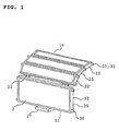
- Fig. 1 is a perspective view of an air filter according to Embodiment 1.
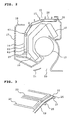
- Fig. 2 is a sectional view of an air conditioner (or air conditioning-refrigerator) to which the air filter has been attached.
- a grille 17 as an air inlet is provided in front of a panel 16 of an air conditioner 15 installed indoors, while an air blower 19 and a heat exchanger 18 are built in behind the air inlet grille 17.
- the heat exchanger 18 is disposed to cover the air blower 19.
- An air outlet 20 is provided in the lower portion of the panel 16. The opening/closing and the air blowing direction of the air outlet 20 are adjusted by a flap 21.
- An air filter 14 is attached between the grille 17 and the heat exchanger 18 in accordance with the sectional layout of the heat exchanger 18.
- a plurality of unit filter frame members 22 in each of which a tabular filter piece 3 having a filtration function to eliminate balls of dust and the like is mounted, are coupled with one another through hinge portions 23 foldably.
- the air filter 14 is attached to cover the whole surface of the heat exchanger 18.
- each of the unit filter frame members 22 has at least one boss portion 25 on one of opposite side surface 35.
- Curved fitting grooves 26 are provided in the panel 16 so as to engage with these boss portions 25. Only the boss portions 25 are inserted and attached into the fitting grooves 26 from a mounting/removing port 40 of an insertion portion 28 which will be described later.
- the air filter 14 is constituted by a plurality of the unit filter frame members 22, the boss portions 25 serving as guide portions 32, and so on.
- the plurality of unit filter frame members 22 are provided with the filter pieces 3 and coupled through the hinges 23.
- the boss portions 25 as the guide portions 32 are columns paired and projecting from the opposite sides 35 of each of the unit filter frame members 22. At least one boss portion 25 projects from each side surface so as to be paired with a corresponding boss portion on the other side surface.
- Fig. 2 shows an example of one pair and two pairs.
- the fitting grooves 26 as guide grooves are formed into sectional U-shapes in the insertion direction of the fitting grooves 26 so that the opening portion of the fitting groove on each side is opposed to the opening portion of the fitting groove on the other side. Thus, only the boss portions 25 as the guide portions 32 on the opposite sides are received in the fitting grooves 26.
- the insertion portion 28 of each of the fitting grooves 26 is constituted by a mounting/removing port 40 having a U-shape in section, and a support plate portion 41 extending downward from the mounting/removing port 40.
- the insertion portion 28 may have only the mounting/removing port 40 without the support plate portion 41.
- the unit filter frame member 22 mounted finally is provided with a handle 27 at its end portion.
- the handle 27 is operated when the air filter 14 is mounted/removed.
- the unit filter frame members 22, the hinge portions 23, the boss portions 25 and the handle 27 are molded integrally of resin. Thus, their manufacturing becomes easy.
- the grille 17 is opened or extracted to mount/remove the air filter 14.
- the air filter 14 is mounted, the air filter 14 is inserted into the mounting/removing ports 40 of the fitting grooves 26 from below the air inlet 17 of the air conditioner 15 so that the boss portions 25 of the unit filter frame members 22 are inserted and fitted into the fitting grooves 26.
- the handle 27 is operated to press the air filter 14 till the last pair of boss portions 25 are fitted in.
- the handle 27 is gripped and pulled out toward the side close to a worker so that the boss portions 25 of the unit filter frame members 22 are extracted from the fitting grooves 26 sequentially while the hinge portions 23 are restored to be straight.
- the mounting/ removal can be performed easily.
- the boss portions 25 are provided on the side surfaces 35 of the unit filter frame members 22, and only the boss portions 25 are fitted into the fitting grooves 26 provided in the panel 16. Accordingly, even if the filter pieces 3 are tabular, even if the thickness of the filter pieces 3 is smaller or larger than the opening width of the fitting grooves 26, or even if the fitting grooves 26 are curved to cover the whole surface of the heat exchanger 18, the air filter 14 can be smoothly mounted/removed in/from the fitting grooves 26 serving as guide grooves.
- the guide grooves 26 are provided in the upstream of the air passage of the heat exchanger 18 so as to be curved along the heat exchanger 18, and the guide portions 32 are inserted into the guide grooves 26 so that the air filter 14 is mounted to be curved to cover the heat exchanger 18. Accordingly, most of the air supplied to the heat exchanger 18 passes though the air filter 14 so that the heat exchanger 18 is surely prevented from contamination.
- the guide grooves 26 are disposed to be curved correspondingly to the heat exchanger 18 disposed to be curved, it is possible to obtain a compact air conditioner 15.
- the air filter 14 is well mated with the curve as a whole.
- the air filter 14 can be well mated with the heat exchanger 18 even if the heat exchanger 18 is curved. Accordingly, while the air not passing through the air filter 14 is prevented from being supplied to the heat exchanger 18, the air conditioner 15 can be made compact effectively.
- the unit filter frame members 22 each having a comparatively small length in the insertion direction when unit filter frame members 22 each having a comparatively small length in the insertion direction are used, the unit filter frame members 22 each having a small length may be formed as unit filter frame members 22 having no boss portion 25. Even if the unit filter frame members 22 having no boss portion 25 are caused to coexist the unit filter frame members 22 having boss portions 25, an air filter 14 having similar effect can be obtained without causing any trouble in mounting/removal of the coupled unit filter frame members 22. In such a manner, the manufacturing of the air filter 14 can be simplified.
- Embodiment 1 has been described in reference to the case where at least one boss portion 25 projects from each of opposite side surfaces 35 of each of the unit filter frame members 22, and only the boss portions 25 are inserted into the curved fitting grooves 26 of the panel 16 so as to mount the coupled unit filter frame members 22.
- the boss portions 25 on the opposite side surfaces 35 of the unit filter frame members 22 are connected with one another through a deformable tabular guide belt 29 which is an elastic body.
- Guide portions 32 each constituted by these boss portions 25 and the guide belt 29 connecting the boss portions 25 are inserted respectively into the curved fitting grooves 26 of the panel 16 so that the coupled unit filter frame members 22 are mounted.
- the guide belt 29 is formed in such a manner that side surfaces 37 of the adjacent boss portions 25 are connected integrally on their front side or back side along the side surfaces 37 of the boss portions 25 of the unit filter frame members 22.
- the front side means the side facing the grille 17 as an air inlet in Fig. 2 when the guide portions 32 are inserted into the fitting grooves 26.
- the back side means the side opposite to the front side.
- the side surfaces 37 of the boss portions 25 are cut correspondingly to the thickness of each of the guide belts 29, and the guide belt 29 is attached to the boss portions 25.
- the guide belt 29 and the side surfaces 37 of the boss portions 25 slide on the inner wall of the corresponding fitting groove 26 in the corresponding fitting groove 26, they have one and the same sliding surface. Thus, mounting and removal are performed more smoothly.
- tabular guide belts 29 and the boss portions 25 on the both side surfaces 35 of the unit filter frame members 22 are manufactured by integral molding of resin, they can be manufactured inexpensively.
- connection through the guide belts 29 may be carried out not on the whole of the boss portions 25 on the side surfaces 35 of the coupled unit filter frame members 22 but on parts of the boss portions 25.
- the boss portions 25 received between the mounting/removing ports 40 of the guide grooves 26 and the front end portions 38 of the guide grooves 26 may be connected through the guide belts 29 while the boss portions 25 on the support plate portion 41 are not connected through the guide belts 29. Similar effect can be obtained.
- the boss portions 25 can be prevented from being detached from the fitting grooves 26 when the guide portions 32 are inserted into the fitting grooves 26 through the mounting/removing ports 40 of the insertion portion 28.
- the air filter 14 can be mounted more smoothly.
- each of Embodiments 1 and 2 has been described as applied to the case where the projecting-direction sections 36 of the boss portions 25 provided on the side surfaces 35 of the unit filter frame members 22 have the same size.
- the sections 36 of the boss portions 25 are designed to increase in size as they approach the mounting/removing ports 40 of the fitting grooves 26 (the insertion side of the guide portions of the air filter) as shown by boss portions 25a, 25b, 25c and 25d.
- each of the guide portions 32 is formed into a wedge-like shape as a whole.
- each of the fitting grooves 26 is formed into a wedge-like shape corresponding to the guide portion 32.
- the boss portions 25 can be attached to the fitting grooves 26 without generating any gap therebetween.
- the air filter 14 can be retained surely on the panel 16, while chattering or the like caused by the vibration of the air conditioner 15 when it is running can be prevented from occurring. It is therefore possible to provide a high-quality air conditioner 15.
- each of the fitting grooves 26 is formed into a wedge-like shape between the front end portion 38 and the mounting/removing port 40.
- the boss portion 25a having a small sectional size is first inserted into each of the wedge-like fitting grooves 26 so that the boss portion 25a is located in the front end portion 38 of the fitting groove 26.
- the boss portions 25b and 25c are located sequentially, and the boss portion 25d having the largest sectional size is located in the mounting/removing port 40. Further, the remaining boss portions 25 each of which may have any desirable sectional size are disposed on the support plate portion 41.
- the coupled unit filter frame members 22 are mounted. That is, of the boss portions 25 of the coupled unit filter frame members 22, a boss portion 25d at one predetermined end which is located in each of the mounting/removing port 40, boss portions 25c and 25b, and a boss portion 25a at the other end which is located in corresponding one of the front end portions are reduced in sectional size sequentially so as to form a wedge-like shape as a whole.
- These wedge-like guide portions 32 are inserted into the guide grooves 26 each formed into a wedge-like shape in the same manner.
- the wedge-like guide portions 32 and the wedge-like guide grooves 26 in this embodiment may be applied to the guide portions 32 each constituted by the guide belt 29 and the boss portions 25 in Embodiment 2. That is, the boss portions 25 are arrayed sequentially in the order of reducing sectional size. These boss portions 25 are connected through the guide belts 29 so as to form wedge-like guide portions 32. The wedge-like guide portions 32 are inserted into the wedge-like guide grooves 26 corresponding thereto.
- the shape is not limited thereto, but may be elliptic or polygonal. In short, any shape may be adopted if the unit filter frame members 22 can be mounted/removed smoothly into/from the curved fitting grooves 26 when the boss portions 25 are inserted into the fitting grooves 26.
- the air filter according to the present invention is inserted into guide grooves provided at the place where the air filter is to be installed.
- Guide portions are provided so that at least one boss portion projects from each of the opposite side surfaces of each unit filter frame member. Accordingly, when the air filter is mounted by inserting the boss portions into the guide grooves, it is possible to obtain an air filter which can be mounted/removed smoothly into/from the guide grooves each of which may have any desirable shape including a curved shape. At that time, the air filter is bent desirably at hinge portions in accordance with the shapes of the guide grooves. Thus, it is possible to obtain an air filter mated with the shapes of the guide grooves.
- the coupled unit filter frame members are reduced in sectional size sequentially as the location goes from the boss portion at a predetermined one end of the coupled unit filter frame members toward the boss portion at the other end in the front end portion of the coupled unit filter frame members, so that each of the guide portions is formed into a wedge-like shape as a whole.
- Each of the guide grooves to which the guide portions are inserted is formed into a wedge-like shape.
- the guide portions are inserted into the guide grooves in the order of increasing the sectional size.
- the guide portions are brought into close contact with the guide grooves. It is therefore possible to obtain an air filter in which chattering or the like caused by vibration or the like is hard to occur.
- guide belts for connecting the boss portions with one another are provided along the side surfaces of the boss portions projecting from the respective side surfaces of the unit filter frame members.
- Each of the guide portions is constituted by the boss portions and the guide belt connecting the boss portions. Accordingly, when the guide portions are inserted into the insertion portions of the guide grooves, the boss portions are prevented from being detached from the guide grooves. It is therefore possible to obtain an air filter which can be mounted more smoothly.
- the unit filter frame members and the guide portions are manufactured by integral molding.
- the air filter can be manufactured inexpensively.
- the guide grooves are provided at the place where the air filter is to be installed.
- the guide portions of the air filter according to the present invention are inserted into the guide grooves so that the air filter is mounted.
- each of the guide grooves is formed to be smaller in sectional size gradually as the location goes from the insertion port of corresponding one of the air filter guide portions toward the front end portion of the groove.
- the air filter guide portions are shaped to be mated with the grooves. Thus, the guide portions are brought into close contact with the guide grooves. It is therefore possible to obtain an air conditioner in which chattering or the like caused by vibration or the like is hard to occur.
- the guide grooves are provided in the upstream of the air passage of the heat exchanger so as to be curved along the heat exchanger.
- the guide portions are inserted into the guide grooves so that the air filter is mounted to be curved to cover the heat exchanger.
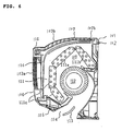
- Fig. 6 is a cross-sectional view of an air conditioner (indoor unit) according to Embodiment 4 of the present invention.
- an air conditioner body 101 is constituted by a base 102, a front panel 105, a front suction grille 106, a top suction grille 107, an air passage 108, an air filter 114, a heat exchanger 111, an air fan 112, and a louver 113.
- the front panel 105 is attached to the front surface of the base 102, and has air inlets 103a and 103b in its front and top surfaces and an air outlet 104 in its front lower portion.
- the front suction grille 106 is attached to the front surface of the front panel 105 removably and closably.
- the top suction grille 107 is attached to the top surface of the top air inlet 103b of the front panel 105.
- the air passage 108 is formed to communicate between the front and top air inlets 103a and 103b and the air outlet 104.
- the air filter 114 is installed removably along the inside of the front and top suction grilles 106 and 107 by use of grooves provided in the front panel 105 as guides.
- the air filter 114 has a length corresponding to the total length of the front and top air inlets 103a and 103b.
- the heat exchanger 111 is divided into three (an upper heat exchanger 111a inclined forward in the upper portion of the air passage, a rear heat exchanger 111b linked to the upper heat exchanger 111a and inclined to the deep portion of the air passage, and a lower heat exchanger 111c linked to the lower portion of the upper heat exchanger 111a and disposed vertically).
- the louver 113 is placed in the exit opening portion of the air outlet 104.
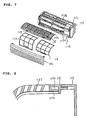
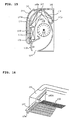
- Fig. 7 shows a main portion perspective view of the air conditioner according to Embodiment 4 of the present invention.
- the top suction grille 107 is attached to the top surface of the top air inlet 103b of the front panel 105.
- the front air filter 114 is installed removably along the inside of the front and top suction grilles 106 and 107. Then, the front air filter 114 reaches the deepest portion of the top air inlet 103b.
- the front and top air inlets 103a and 103b can be covered with only the front air filter 114.
- the front air filter 114 may be divided into two with respect to the width of the air conditioner as shown in Fig. 7.
- Fig. 8 is an enlarged sectional view of the portion where the front end portion of the top suction grille 107 is attached to the front panel 105.
- a protrusion portion 107b is provided in the front end portion of the top suction grille 107 so as to project all over the grille width.
- a reception portion 105b into which this protrusion portion 107b can be plugged is provided in the portion of the front panel 105 where the top suction grille 107 is to be attached.
- the protrusion portion 107b is plugged into the reception portion 105b so that the top suction grille 107 is positioned.
- a cushion material may be put between the protrusion portion 107b and the reception portion 105b. This cushion material may be attached either to the protrusion portion 107b or to the reception portion 105b.
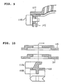
- Fig. 9 is an enlarged sectional view showing the portion where the rear end portion of the top suction grille 107 is fixed to the front panel 105.
- the top suction panel 107 is placed over the front panel 105 so that a fixing hole 105c formed in the front panel 105 is aligned with a fixing hole 107c formed in the top suction grille 107.
- a lock part 115 extends through the aforementioned two holes so as to fix the top suction grille 107 in place.
- the lock part 115 is constituted by a lock portion 115a and an operating portion 115b.
- the lock portion 115a is a portion to be inserted into the fixing hole 105c formed in the front panel 105 and the fixing hole 107c formed in the top suction grille 107.
- the lock portion 115a has a depth corresponding to the thickness of the fixing holes 105c and 107c and a fixing hook portion. According to the shape shown in Fig. 10, the lock portion 115a is slid to the right after insertion so that the front panel 105 and the top suction grille 107 can be nipped and fixed by the lock portion 115a.
- the operating portion 115b of the lock part 115 may be formed into an arrow-like shape as illustrated. By forming the operating portion 115b into such a shape, an operator can know the operating direction easily. Further, the lock part 115 may have a color tone different from those of the other parts surrounding the lock part 115 so that a worker can recognize the existence of the lock part easily.
- the fixing hole 105c formed in the front panel 105 may have a cuspidate shape as shown in Fig. 11 in order to receive the fixing hook portion of the lock portion 115a of the lock part 115 easily.
- Fig. 12 is a cross-sectional view of the air conditioner, showing the state where the front suction grille 106 has been flipped open. Since the front suction grille 106 has hinge portions on its opposite sides and is mounted on the front panel therethrough as shown in Fig. 7, the front suction grille 106 can be flipped open as shown in Fig. 12. In this state, the lock part 115 is located in a position where the lock part 115 can be operated. In the case of a normal use state as shown in Fig. 6, the lock part 115 does not appear externally. Thus, there is no fear that the lock part 115 spoils the design of the air conditioner.
- the air conditioner according to Embodiment 4 of the present invention is configured thus, the mounting/removing work of the top suction grille can be performed by only the operation from the side close to a worker. Thus, the work can be performed more easily and more safely.
- the air filter can cover the front and top air inlets without being divided into two in the front/rear direction. Accordingly, the air filter can be removed easily only by the operation from the front side, and the labor for cleaning can be reduced.
- Fig. 13 is a plan view showing the state where the top suction grille 107 is mounted on the body 101 including the front panel 105 according to Embodiment 5 of the present invention.
- the width of its front end portion located on the deep side of the front panel 105 is made narrower than the width of its rear end portion located on the front side of the front panel 105.
- the top suction grille mounting portion of the front panel 105 has a shape mated with the shape of the top suction grille 107.
- the top suction grille 107 can be positioned easily by a simple method in which the protrusion portion 107b provided in the front end portion of the top suction grille 107 is plugged into the reception portion 105b of the front panel 105.
- the workability in the mounting/removing work carried out overhead is improved.
- Fig. 14 is an enlarged sectional view showing the portion where the rear end portion of the top suction grille 107 is fixed to the front panel 105 according to Embodiment 6 of the present invention.
- the top suction grille 107 is placed over the front panel 105.
- At least one protrusion portion 107d is provided in the top suction grille 107 so as to enter the opening of the top air inlet 103b of the front panel 105.
- a protrusion portion is provided in the front end portion of a top suction grille, and fitted into a reception portion of a front panel. Then, the top suction grille is fixed to the front panel by a lock part using hole portions provided in the rear end portions of the top suction grille and the front panel. Accordingly, the work of mounting/removing the grille or the air filter can be carried out by a simple method of performing the operation on the side close to a worker. It is therefore possible to carry out the work more easily and more safely.
- the lock part is formed into an arrow-like shape. Accordingly, the direction of the operation can be shown to the operator in an easy-to-understand way. Further, the lock part is made to have a color tone different from those of the other parts surrounding the lock part. Accordingly, the worker can recognize the existence of the lock part easily.
- the width of its front end portion located on the deep side of the front panel is made narrower than the width of its rear end portion. Accordingly, the top suction grille 107 can be positioned easily so that the workability in the mounting/removing work carried out overhead is improved.
- the air filter can cover all the air inlet surface without being divided in the front/rear direction, so that it becomes easy to remove the air filter. This contributes to reduction in manufacturing cost, and further results in labor saving for cleaning.
Description
- The present invention relates to an air filter and an air conditioner having the air filter.
- As a conventional air filter of an air conditioner, there is a technique disclosed in Japanese Patent Laid-Open No. 226024/1994. Fig. 5 is a perspective view showing the air filter disclosed in the aforementioned publication. In Fig. 5, the reference numeral 1 represents an air filter; and 2, a tabular unit filter member, in which a net material using a general- purpose resin material such as polyethylene, nylon or the like is employed because the tabular unit filter member is required to have a filtration function to eliminate balls of dust and the like and a function as hinge portions when folded. Then, each of the unit filter members 2 has a filter piece 3 having opposite sides retained by
frame pieces 6, which will be described later. The unit filter members 2 are formed with only the filter pieces 3 and coupled with one another foldably through hinge portions 4 where the opposite sides of the unit filter members 2 are not retained by theframe pieces 6. - The
frame pieces 6 are molded of resin such as polyethylene or the like integrally with the filter pieces 3. Then, flat frames 7 and a handle 8 are provided on theframe pieces 6. Each of theframe pieces 6 has a shape to be fitted into a fitting groove 11 of anair conditioner 10, and formed to be slightly shorter than the interval between the hinge portions 4 and 4 of the unit filter member 2 retained by theframe pieces 6. A plurality ofsuch frame pieces 6 are disposed in symmetrical positions. Then, chamfered portions 9 are provided in the opposite end portions of each of theframe pieces 6 so as to insert and fit theframe pieces 6 easily into the fitting groove 11 at the time of insertion and fitting and so as to prevent angular portions of theframe piece 6 from abutting against anything at the time of folding. A pair of flat frames 7 are provided at the top and bottom of the air filter 1 so as to form the top and bottom of a framework. The flat frames 7 are formed integrally with the left andright frame pieces 6. A handle 8 is provided on the bottom-side flat frame 7. The handle 8 is used to operate the air filter 1 with fingers when the air filter 1 is mounted on or removed from theair conditioner 10. - Next, description will be made below about the method for mounting and removing the air filter 1.
- As shown in Fig. 5, when the air filter 1 is mounted, the top-side flat frame 7 is plugged into a mounting/removing port 12 from the lower side of an air inlet 13 of the
air conditioner 10 while the air filter 1 is bent. Then, the left andright frame pieces 6 are fitted into the fitting grooves 11 at the opposite ends of the mounting/removing port 12. In the same manner, theremaining frame pieces 6 are inserted into the fitting grooves 11 of theair conditioner 10 sequentially while the hinge portions 4 are turned back vertically in the same manner. Then, the handle 8 is operated to press the air filter 1 until the last pair offrame pieces 6 are fitted in. - In addition, the handle 8 is projected from the lower side of the mounting/removing port 12 of the
air conditioner 10 so as to be gripped easily when the air filter 1 is removed. When the air filter 1 is removed, the handle 8 projecting from the lower side of the mounting/removing port 12 is gripped and pulled so as to extract theframe pieces 6 sequentially from the fitting grooves 11 of theair conditioner 10. Then, the air filter 1 is removed from the lower side of theair conditioner 10 while the hinge portions 4 are restored to be straight. - In such a manner, the conventional air filter 1 of the
air conditioner 10 is mounted on theair conditioner 10 by inserting theframe pieces 6 on the opposite sides into the fitting grooves 11. However, each of theframe pieces 6 has a considerable length in the direction in which theframe piece 6 is inserted. Thus, there is a problem that the air filter 1 cannot be mounted or removed smoothly when the fitting grooves 11 are curved. - In addition, when the air filter 1 is mounted on the
air conditioner 10, theframe pieces 6 on the opposite sides are inserted into the fitting grooves 11 while the filter pieces 3 and so on are inserted into the mounting/removing port 12 which is formed to follow the fitting grooves 11 and which has the same opening width. Accordingly, each of the filter pieces and so on cannot be made thicker than each of theframe pieces 6. Thus, there is a problem that the filter pieces cannot be thickened for the purpose of enhancing the air cleaning function of the filter pieces. - In addition, Figs. 15 and 16 are views showing a conventional air conditioner (indoor unit), for example, disclosed in Japanese Patent Laid-Open No. 232025/1998.
- In Fig. 16, hollow groove portions 107a provided on the left and right sides of a
top suction grille 107 slide on and are fitted onto rails 105a provided on the upper left and right of afront panel 105, so that thetop suction grille 107 is removably mounted on thefront panel 105. Then, an air filter is divided into front and rear air filters. Therear air filter 110 is designed to be attached to thetop suction grille 107 so as to be mounted/removed in accordance with the mounting/removal of thetop suction grille 107. - The removable top suction grille and the air filter in the conventional air conditioner are configured thus. Accordingly, the top suction grille has to be mounted/removed in accordance with the left and right guide rails. Positioning is required for the mounting/removing work, although this work is an overhead work carried out on a chair, a table or the like. Therefore, the work is difficult. In addition, the air filter is divided in two, that is, front and rear air filters. Particularly since the rear air filter is fixed to the top suction grille, the workability in mounting/removing the top suction grille is deteriorated, and further the labor for cleaning the filter is increased. In addition, this also results in increase in the manufacturing cost.
- JP-09315142 discloses a detachable air filter for an air conditioner for a construction vehicle. The air filter is provided in the form of two or more foldable sections which allow the filter to be easily attached or detached from an air filter housing in the air conditioner.
- The present invention was developed to solve the foregoing problems. It is an object of the invention to provide an air filter which can be removably mounted smoothly into guide grooves having any various shape including a curved shape.
- In addition, it is another object of the invention to provide an air filter in which each of filter pieces can be thickened desirably so that the performance can be enhanced.
- In addition, it is a further object of the invention to provide an air filter in which it is difficult to produce chattering due to vibration when an air conditioner is running.
- In addition, it is a still further object of the invention to obtain an air filter which is hardly detached from guide grooves when the air filter is attached to the air conditioner.
- In addition, it is another object of the invention to provide an air filter which can be manufactured inexpensively.
- In addition, it is a further object of the invention to provide an air conditioner to which such an air filter has been attached, which is high in quality and performance, and which is capable of preventing a heat exchanger from contamination.
- Further, it is a still further object of the invention to provide an air conditioner in which the work of mounting/removing a top suction grille can be carried out easily, and the work of cleaning can be simplified.
- According to the invention there is provided an air filter as set out in claim 1. Preferred features of the invention are set out in claims 2 to 7.
-
- Fig. 1 is a perspective view of an air filter according to Embodiment 1 of the present invention;
- Fig. 2 is a sectional view of an air conditioner according to Embodiment 1 of the present invention;
- Fig. 3 is a partial configuration view of an air filter according to Embodiment 2 of the present invention;
- Fig. 4 is a view showing a wedge-like guide portion and a wedge-like guide groove according to Embodiment 3 of the present invention;
- Fig. 5 is a perspective view showing a conventional air filter;
- Fig. 6 is a cross-sectional view of an air conditioner according to Embodiment 4 of the present invention;
- Fig. 7 is a main portion perspective view of the air conditioner according to Embodiment 4 of the present invention;
- Fig. 8 is an enlarged sectional view showing the portion where the front end portion of a top suction grille is mounted on a front panel according to Embodiment 4 of the present invention;
- Fig. 9 is an enlarged sectional view showing the portion where the rear end portion of the top suction grille is fixed to the front panel according to Embodiment 4 of the present invention;
- Fig. 10 is a plan sectional view showing the portion where a lock part is attached;
- Fig. 11 is a perspective view showing the portion where the lock part is attached;
- Fig. 12 is a cross-sectional view of the air conditioner when a front suction grille is flipped open;
- Fig. 13 is a plan view showing the attachment of a top suction grille according to Embodiment 5 of the present invention;
- Fig. 14 is an enlarged sectional view of the rear end portion of a top suction grille
according to
Embodiment 6 of the present invention; - Fig. 15 is a cross-sectional view of a conventional air conditioner; and
- Fig. 16 is a partially enlarged view of the conventional air conditioner.
-
- Embodiment 1 of the present invention will be described below with reference to Figs. 1 and 2.
- Fig. 1 is a perspective view of an air filter according to Embodiment 1. Fig. 2 is a sectional view of an air conditioner (or air conditioning-refrigerator) to which the air filter has been attached.
- In Figs. 1 and 2, a
grille 17 as an air inlet is provided in front of apanel 16 of anair conditioner 15 installed indoors, while anair blower 19 and aheat exchanger 18 are built in behind theair inlet grille 17. Theheat exchanger 18 is disposed to cover theair blower 19. Anair outlet 20 is provided in the lower portion of thepanel 16. The opening/closing and the air blowing direction of theair outlet 20 are adjusted by aflap 21. - An
air filter 14 is attached between thegrille 17 and theheat exchanger 18 in accordance with the sectional layout of theheat exchanger 18. In theair filter 14, a plurality of unitfilter frame members 22 in each of which a tabular filter piece 3 having a filtration function to eliminate balls of dust and the like is mounted, are coupled with one another throughhinge portions 23 foldably. Theair filter 14 is attached to cover the whole surface of theheat exchanger 18. - Then, each of the unit
filter frame members 22 has at least oneboss portion 25 on one ofopposite side surface 35. Curvedfitting grooves 26 are provided in thepanel 16 so as to engage with theseboss portions 25. Only theboss portions 25 are inserted and attached into thefitting grooves 26 from a mounting/removingport 40 of aninsertion portion 28 which will be described later. - The
air filter 14 is constituted by a plurality of the unitfilter frame members 22, theboss portions 25 serving asguide portions 32, and so on. The plurality of unitfilter frame members 22 are provided with the filter pieces 3 and coupled through thehinges 23. - The
boss portions 25 as theguide portions 32 are columns paired and projecting from theopposite sides 35 of each of the unitfilter frame members 22. At least oneboss portion 25 projects from each side surface so as to be paired with a corresponding boss portion on the other side surface. Fig. 2 shows an example of one pair and two pairs. - The
fitting grooves 26 as guide grooves are formed into sectional U-shapes in the insertion direction of thefitting grooves 26 so that the opening portion of the fitting groove on each side is opposed to the opening portion of the fitting groove on the other side. Thus, only theboss portions 25 as theguide portions 32 on the opposite sides are received in thefitting grooves 26. - As shown in Fig. 2, the
insertion portion 28 of each of thefitting grooves 26 is constituted by a mounting/removingport 40 having a U-shape in section, and a support plate portion 41 extending downward from the mounting/removingport 40. - However, according to the shape, the
insertion portion 28 may have only the mounting/removingport 40 without the support plate portion 41. - Of the unit
filter frame members 22 coupled with one another, the unitfilter frame member 22 mounted finally is provided with ahandle 27 at its end portion. Thehandle 27 is operated when theair filter 14 is mounted/removed. - In addition, the unit
filter frame members 22, thehinge portions 23, theboss portions 25 and thehandle 27 are molded integrally of resin. Thus, their manufacturing becomes easy. - Next, description will be made on the method for mounting and removing the
air filter 14. - Although the method for mounting/removing differs in accordance with the kind of
air conditioner 15, thegrille 17 is opened or extracted to mount/remove theair filter 14. When theair filter 14 is mounted, theair filter 14 is inserted into the mounting/removingports 40 of thefitting grooves 26 from below theair inlet 17 of theair conditioner 15 so that theboss portions 25 of the unitfilter frame members 22 are inserted and fitted into thefitting grooves 26. Then, thehandle 27 is operated to press theair filter 14 till the last pair ofboss portions 25 are fitted in. - On the other hand, when the
air filter 14 is removed, thehandle 27 is gripped and pulled out toward the side close to a worker so that theboss portions 25 of the unitfilter frame members 22 are extracted from thefitting grooves 26 sequentially while thehinge portions 23 are restored to be straight. - Incidentally, at the time of mounting, if the unit
filter frame member 22 in the end portion having the handle 27 (the last unitfilter frame member 22 having the handle 27) is located on the aforementioned support plate portion 41, the mounting/ removal can be performed easily. - As described above, the
boss portions 25 are provided on the side surfaces 35 of the unitfilter frame members 22, and only theboss portions 25 are fitted into thefitting grooves 26 provided in thepanel 16. Accordingly, even if the filter pieces 3 are tabular, even if the thickness of the filter pieces 3 is smaller or larger than the opening width of thefitting grooves 26, or even if thefitting grooves 26 are curved to cover the whole surface of theheat exchanger 18, theair filter 14 can be smoothly mounted/removed in/from thefitting grooves 26 serving as guide grooves. - In addition, when the
air filter 14 is mounted, only theboss portions 25 on the opposite sides are inserted into theguide grooves 26 while the unitfilter frame members 22 coupled with each other are left free. It is therefore possible to make the thickness of the filter pieces 3 larger than the opening width of theguide grooves 26. Thus, filter pieces having high performance can be used so that the performance of the air filter can be improved. - In addition, the
guide grooves 26 are provided in the upstream of the air passage of theheat exchanger 18 so as to be curved along theheat exchanger 18, and theguide portions 32 are inserted into theguide grooves 26 so that theair filter 14 is mounted to be curved to cover theheat exchanger 18. Accordingly, most of the air supplied to theheat exchanger 18 passes though theair filter 14 so that theheat exchanger 18 is surely prevented from contamination. In addition, since theguide grooves 26 are disposed to be curved correspondingly to theheat exchanger 18 disposed to be curved, it is possible to obtain acompact air conditioner 15. - In addition, when unit
filter frame members 22 each having a comparatively small length in the insertion direction are used for large-curvature portions in thefitting grooves 26 as shown in Fig. 2, theair filter 14 is well mated with the curve as a whole. Thus, theair filter 14 can be well mated with theheat exchanger 18 even if theheat exchanger 18 is curved. Accordingly, while the air not passing through theair filter 14 is prevented from being supplied to theheat exchanger 18, theair conditioner 15 can be made compact effectively. - Further, when unit
filter frame members 22 each having a comparatively small length in the insertion direction are used, the unitfilter frame members 22 each having a small length may be formed as unitfilter frame members 22 having noboss portion 25. Even if the unitfilter frame members 22 having noboss portion 25 are caused to coexist the unitfilter frame members 22 havingboss portions 25, anair filter 14 having similar effect can be obtained without causing any trouble in mounting/removal of the coupled unitfilter frame members 22. In such a manner, the manufacturing of theair filter 14 can be simplified. - Embodiment 1 has been described in reference to the case where at least one
boss portion 25 projects from each of opposite side surfaces 35 of each of the unitfilter frame members 22, and only theboss portions 25 are inserted into the curvedfitting grooves 26 of thepanel 16 so as to mount the coupled unitfilter frame members 22. However, in this embodiment, as shown in Fig. 3, of theboss portions 25 on the opposite side surfaces 35 of the unitfilter frame members 22, theboss portions 25 on the same side are connected with one another through a deformabletabular guide belt 29 which is an elastic body.Guide portions 32 each constituted by theseboss portions 25 and theguide belt 29 connecting theboss portions 25 are inserted respectively into the curvedfitting grooves 26 of thepanel 16 so that the coupled unitfilter frame members 22 are mounted. - The
guide belt 29 is formed in such a manner that side surfaces 37 of theadjacent boss portions 25 are connected integrally on their front side or back side along the side surfaces 37 of theboss portions 25 of the unitfilter frame members 22. Here, the front side means the side facing thegrille 17 as an air inlet in Fig. 2 when theguide portions 32 are inserted into thefitting grooves 26. On the other hand, the back side means the side opposite to the front side. - In addition, as shown in Fig. 3, the side surfaces 37 of the
boss portions 25 are cut correspondingly to the thickness of each of theguide belts 29, and theguide belt 29 is attached to theboss portions 25. As a result, when theguide belt 29 and the side surfaces 37 of theboss portions 25 slide on the inner wall of the correspondingfitting groove 26 in the correspondingfitting groove 26, they have one and the same sliding surface. Thus, mounting and removal are performed more smoothly. - Further, when the
tabular guide belts 29 are disposed on the front side of the unitfilter frame members 22, there is no fear that theguide belts 29 interfere with the mounting/removingports 40 of thefitting grooves 26 when theair filter 14 is mounted/removed. Thus, the performance of mounting/removal is improved. - In addition, when the
tabular guide belts 29 and theboss portions 25 on the both side surfaces 35 of the unitfilter frame members 22 are manufactured by integral molding of resin, they can be manufactured inexpensively. - In addition, the connection through the
guide belts 29 may be carried out not on the whole of theboss portions 25 on the side surfaces 35 of the coupled unitfilter frame members 22 but on parts of theboss portions 25. For example, in the air conditioner of Fig. 2, when theair filter 14 is mounted, theboss portions 25 received between the mounting/removingports 40 of theguide grooves 26 and the front end portions 38 of theguide grooves 26 may be connected through theguide belts 29 while theboss portions 25 on the support plate portion 41 are not connected through theguide belts 29. Similar effect can be obtained. - As described above, by use of the
guide portions 32 according to this embodiment, theboss portions 25 can be prevented from being detached from thefitting grooves 26 when theguide portions 32 are inserted into thefitting grooves 26 through the mounting/removingports 40 of theinsertion portion 28. Thus, theair filter 14 can be mounted more smoothly. - Each of Embodiments 1 and 2 has been described as applied to the case where the projecting-
direction sections 36 of theboss portions 25 provided on the side surfaces 35 of the unitfilter frame members 22 have the same size. However, as shown in Fig. 4, in this embodiment, thesections 36 of theboss portions 25 are designed to increase in size as they approach the mounting/removingports 40 of the fitting grooves 26 (the insertion side of the guide portions of the air filter) as shown by boss portions 25a, 25b, 25c and 25d. Thus, each of theguide portions 32 is formed into a wedge-like shape as a whole. In addition, each of thefitting grooves 26 is formed into a wedge-like shape corresponding to theguide portion 32. Accordingly, at the time of mounting, theboss portions 25 can be attached to thefitting grooves 26 without generating any gap therebetween. Thus, theair filter 14 can be retained surely on thepanel 16, while chattering or the like caused by the vibration of theair conditioner 15 when it is running can be prevented from occurring. It is therefore possible to provide a high-quality air conditioner 15. - In actual mounting, as shown in Fig. 4, the section of the front end portion 38 is reduced while the section of the mounting/removing
port 40 of theinsertion portion 28 is increased. That is, thefitting groves 26 are formed so that the opening width of each of thefitting grooves 26 is reduced as it approaches the front end portion 38. Thus, each of thefitting grooves 26 is formed into a wedge-like shape between the front end portion 38 and the mounting/removingport 40. The boss portion 25a having a small sectional size is first inserted into each of the wedge-likefitting grooves 26 so that the boss portion 25a is located in the front end portion 38 of thefitting groove 26. Succeedingly, the boss portions 25b and 25c are located sequentially, and the boss portion 25d having the largest sectional size is located in the mounting/removingport 40. Further, the remainingboss portions 25 each of which may have any desirable sectional size are disposed on the support plate portion 41. Thus, the coupled unitfilter frame members 22 are mounted. That is, of theboss portions 25 of the coupled unitfilter frame members 22, a boss portion 25d at one predetermined end which is located in each of the mounting/removingport 40, boss portions 25c and 25b, and a boss portion 25a at the other end which is located in corresponding one of the front end portions are reduced in sectional size sequentially so as to form a wedge-like shape as a whole. These wedge-like guide portions 32 are inserted into theguide grooves 26 each formed into a wedge-like shape in the same manner. - Incidentally, not to say, the wedge-
like guide portions 32 and the wedge-like guide grooves 26 in this embodiment may be applied to theguide portions 32 each constituted by theguide belt 29 and theboss portions 25 in Embodiment 2. That is, theboss portions 25 are arrayed sequentially in the order of reducing sectional size. Theseboss portions 25 are connected through theguide belts 29 so as to form wedge-like guide portions 32. The wedge-like guide portions 32 are inserted into the wedge-like guide grooves 26 corresponding thereto. - Although the present invention was described as applied to the case where the
boss portions 25 are circular in section, the shape is not limited thereto, but may be elliptic or polygonal. In short, any shape may be adopted if the unitfilter frame members 22 can be mounted/removed smoothly into/from the curvedfitting grooves 26 when theboss portions 25 are inserted into thefitting grooves 26. - As described in the Embodiments 1 to 3, the air filter according to the present invention is inserted into guide grooves provided at the place where the air filter is to be installed. Guide portions are provided so that at least one boss portion projects from each of the opposite side surfaces of each unit filter frame member. Accordingly, when the air filter is mounted by inserting the boss portions into the guide grooves, it is possible to obtain an air filter which can be mounted/removed smoothly into/from the guide grooves each of which may have any desirable shape including a curved shape. At that time, the air filter is bent desirably at hinge portions in accordance with the shapes of the guide grooves. Thus, it is possible to obtain an air filter mated with the shapes of the guide grooves.
- In addition, the coupled unit filter frame members are reduced in sectional size sequentially as the location goes from the boss portion at a predetermined one end of the coupled unit filter frame members toward the boss portion at the other end in the front end portion of the coupled unit filter frame members, so that each of the guide portions is formed into a wedge-like shape as a whole. Each of the guide grooves to which the guide portions are inserted is formed into a wedge-like shape. In accordance with the direction of the wedges, the guide portions are inserted into the guide grooves in the order of increasing the sectional size. Thus, the guide portions are brought into close contact with the guide grooves. It is therefore possible to obtain an air filter in which chattering or the like caused by vibration or the like is hard to occur.
- In addition, guide belts for connecting the boss portions with one another are provided along the side surfaces of the boss portions projecting from the respective side surfaces of the unit filter frame members. Each of the guide portions is constituted by the boss portions and the guide belt connecting the boss portions. Accordingly, when the guide portions are inserted into the insertion portions of the guide grooves, the boss portions are prevented from being detached from the guide grooves. It is therefore possible to obtain an air filter which can be mounted more smoothly.
- In addition, the unit filter frame members and the guide portions are manufactured by integral molding. Thus, the air filter can be manufactured inexpensively.
- Further, as described in the Embodiments 1 to 3, in the air conditioner according to the present invention, the guide grooves are provided at the place where the air filter is to be installed. The guide portions of the air filter according to the present invention are inserted into the guide grooves so that the air filter is mounted. Thus, by the aforementioned effect inherent to the air filter, the quality of the air conditioner is improved.
- In addition, each of the guide grooves is formed to be smaller in sectional size gradually as the location goes from the insertion port of corresponding one of the air filter guide portions toward the front end portion of the groove. The air filter guide portions are shaped to be mated with the grooves. Thus, the guide portions are brought into close contact with the guide grooves. It is therefore possible to obtain an air conditioner in which chattering or the like caused by vibration or the like is hard to occur.
- In addition, the guide grooves are provided in the upstream of the air passage of the heat exchanger so as to be curved along the heat exchanger. The guide portions are inserted into the guide grooves so that the air filter is mounted to be curved to cover the heat exchanger. Thus, most of the air supplied to the heat exchanger passes through the air filter, so that the heat exchanger is surely prevented from contamination.
- Fig. 6 is a cross-sectional view of an air conditioner (indoor unit) according to Embodiment 4 of the present invention. In Fig. 6, an
air conditioner body 101 is constituted by abase 102, afront panel 105, afront suction grille 106, atop suction grille 107, anair passage 108, anair filter 114, aheat exchanger 111, anair fan 112, and alouver 113. Thefront panel 105 is attached to the front surface of thebase 102, and hasair inlets 103a and 103b in its front and top surfaces and anair outlet 104 in its front lower portion. Thefront suction grille 106 is attached to the front surface of thefront panel 105 removably and closably. Thetop suction grille 107 is attached to the top surface of the top air inlet 103b of thefront panel 105. Theair passage 108 is formed to communicate between the front andtop air inlets 103a and 103b and theair outlet 104. Theair filter 114 is installed removably along the inside of the front andtop suction grilles front panel 105 as guides. Theair filter 114 has a length corresponding to the total length of the front andtop air inlets 103a and 103b. Theheat exchanger 111 is divided into three (an upper heat exchanger 111a inclined forward in the upper portion of the air passage, arear heat exchanger 111b linked to the upper heat exchanger 111a and inclined to the deep portion of the air passage, and alower heat exchanger 111c linked to the lower portion of the upper heat exchanger 111a and disposed vertically). Thelouver 113 is placed in the exit opening portion of theair outlet 104. - Fig. 7 shows a main portion perspective view of the air conditioner according to Embodiment 4 of the present invention. In Fig. 7, the
top suction grille 107 is attached to the top surface of the top air inlet 103b of thefront panel 105. While being curved with the grooves provided in thefront panel 105 as guides, thefront air filter 114 is installed removably along the inside of the front andtop suction grilles front air filter 114 reaches the deepest portion of the top air inlet 103b. Thus, the front andtop air inlets 103a and 103b can be covered with only thefront air filter 114. However, thefront air filter 114 may be divided into two with respect to the width of the air conditioner as shown in Fig. 7. - Fig. 8 is an enlarged sectional view of the portion where the front end portion of the
top suction grille 107 is attached to thefront panel 105. A protrusion portion 107b is provided in the front end portion of thetop suction grille 107 so as to project all over the grille width. In addition, a reception portion 105b into which this protrusion portion 107b can be plugged is provided in the portion of thefront panel 105 where thetop suction grille 107 is to be attached. The protrusion portion 107b is plugged into the reception portion 105b so that thetop suction grille 107 is positioned. In order to suppress chattering during the running of the air conditioner, a cushion material may be put between the protrusion portion 107b and the reception portion 105b. This cushion material may be attached either to the protrusion portion 107b or to the reception portion 105b. - Fig. 9 is an enlarged sectional view showing the portion where the rear end portion of the
top suction grille 107 is fixed to thefront panel 105. Thetop suction panel 107 is placed over thefront panel 105 so that a fixing hole 105c formed in thefront panel 105 is aligned with a fixinghole 107c formed in thetop suction grille 107. Alock part 115 extends through the aforementioned two holes so as to fix thetop suction grille 107 in place. - The fixing method of the
lock part 115 will be described with reference to the plan sectional view of Fig. 10 and the perspective view of Fig. 11. As shown in Fig. 10, thelock part 115 is constituted by alock portion 115a and an operatingportion 115b. Thelock portion 115a is a portion to be inserted into the fixing hole 105c formed in thefront panel 105 and the fixinghole 107c formed in thetop suction grille 107. Thelock portion 115a has a depth corresponding to the thickness of the fixingholes 105c and 107c and a fixing hook portion. According to the shape shown in Fig. 10, thelock portion 115a is slid to the right after insertion so that thefront panel 105 and thetop suction grille 107 can be nipped and fixed by thelock portion 115a. - Incidentally, the operating
portion 115b of thelock part 115 may be formed into an arrow-like shape as illustrated. By forming the operatingportion 115b into such a shape, an operator can know the operating direction easily. Further, thelock part 115 may have a color tone different from those of the other parts surrounding thelock part 115 so that a worker can recognize the existence of the lock part easily. - In addition, the fixing hole 105c formed in the
front panel 105 may have a cuspidate shape as shown in Fig. 11 in order to receive the fixing hook portion of thelock portion 115a of thelock part 115 easily. - Fig. 12 is a cross-sectional view of the air conditioner, showing the state where the
front suction grille 106 has been flipped open. Since thefront suction grille 106 has hinge portions on its opposite sides and is mounted on the front panel therethrough as shown in Fig. 7, thefront suction grille 106 can be flipped open as shown in Fig. 12. In this state, thelock part 115 is located in a position where thelock part 115 can be operated. In the case of a normal use state as shown in Fig. 6, thelock part 115 does not appear externally. Thus, there is no fear that thelock part 115 spoils the design of the air conditioner. - Since the air conditioner according to Embodiment 4 of the present invention is configured thus, the mounting/removing work of the top suction grille can be performed by only the operation from the side close to a worker. Thus, the work can be performed more easily and more safely.
- In addition, the air filter can cover the front and top air inlets without being divided into two in the front/rear direction. Accordingly, the air filter can be removed easily only by the operation from the front side, and the labor for cleaning can be reduced.
- Fig. 13 is a plan view showing the state where the
top suction grille 107 is mounted on thebody 101 including thefront panel 105 according to Embodiment 5 of the present invention. As for the shape of thetop suction grille 107, the width of its front end portion located on the deep side of thefront panel 105 is made narrower than the width of its rear end portion located on the front side of thefront panel 105. On the other hand, the top suction grille mounting portion of thefront panel 105 has a shape mated with the shape of thetop suction grille 107. Thus, thetop suction grille 107 can be positioned easily by a simple method in which the protrusion portion 107b provided in the front end portion of thetop suction grille 107 is plugged into the reception portion 105b of thefront panel 105. Thus, the workability in the mounting/removing work carried out overhead is improved. - Fig. 14 is an enlarged sectional view showing the portion where the rear end portion of the
top suction grille 107 is fixed to thefront panel 105 according toEmbodiment 6 of the present invention. Thetop suction grille 107 is placed over thefront panel 105. At least one protrusion portion 107d is provided in thetop suction grille 107 so as to enter the opening of the top air inlet 103b of thefront panel 105. As a result, when thetop suction grille 107 is mounted, thetop suction grille 107 can be prevented from slipping down toward the side close to a worker even if thelock part 115 is not inserted. Thus, the workability in inserting/extracting thelock part 115 can be improved. - In addition, if the aforementioned protrusion portion is provided in the
front panel 105 so as to enter an opening formed in thetop suction grille 107, similar effect can be obtained. - As described in the Embodiments 4 to 6, in the air conditioner according to the present invention, a protrusion portion is provided in the front end portion of a top suction grille, and fitted into a reception portion of a front panel. Then, the top suction grille is fixed to the front panel by a lock part using hole portions provided in the rear end portions of the top suction grille and the front panel. Accordingly, the work of mounting/removing the grille or the air filter can be carried out by a simple method of performing the operation on the side close to a worker. It is therefore possible to carry out the work more easily and more safely.
- In addition, the lock part is formed into an arrow-like shape. Accordingly, the direction of the operation can be shown to the operator in an easy-to-understand way. Further, the lock part is made to have a color tone different from those of the other parts surrounding the lock part. Accordingly, the worker can recognize the existence of the lock part easily.
- In addition, as for the shape of the
top suction grille 107, the width of its front end portion located on the deep side of the front panel is made narrower than the width of its rear end portion. Accordingly, thetop suction grille 107 can be positioned easily so that the workability in the mounting/removing work carried out overhead is improved. - Further, the air filter can cover all the air inlet surface without being divided in the front/rear direction, so that it becomes easy to remove the air filter. This contributes to reduction in manufacturing cost, and further results in labor saving for cleaning.
Claims (6)
- An air filter (14) comprising a plurality of unit filter frame members (22) each of which has a filter piece (3) and which are coupled with one another through hinge portions (23) foldably,
wherein said unit frame members (22) have guide portions (32) arranged for insertion into guide grooves (26) provided in a region of apparatus in which said air filter (14) can be installed, characterised in that said guide portions (32) include plural pairs of boss portions (25) oppositely projecting on the opposite side surfaces (35) of said unit filter frame members (22), wherein sectional sizes of said boss portions (25) are so selected that a sectional size of a boss portion (25a) nearest a top end (38) of the unit filter frame members (22) coupled with one another is smallest and sectional sizes of following boss portions (25b, 25c, 25d) arranged in the direction toward the opposite end of the unit filter frame members (22) are gradually increased, on one of said opposite side surfaces (35). - An air filter (14) according to claim 1, wherein said guide portions (32) further include a guide belt (29) connecting side surfaces of boss portions (25) projecting on one of said opposite side surfaces (35) of said unit filter frame members (22).
- An air filter (14) according to claims 1 or 2, wherein said unit filter frame members (22) and guide portions (32) are manufactured by integral moding.
- An air conditioner comprising an air filter (14) according to any one of claims 1 to 3, a heat exchanger (18) and an air blower (19) installed in a panel (16) having an air inlet and an air outlet, for carrying air sucked from said air inlet through the air filter, heat-exchanging the carried air with a refrigerant in said heat exchanger and blowing the heat-exchanged air from said air outlet (20); the air conditioner further comprising guide grooves (26) provided at a region where said air filter (14) is installed, wherein guide portions (32) of said air filter (14) are inserted into said guide grooves (26) when said air filter (14) is installed.
- An air conditioner according to claim 4, wherein the each of the guide grooves (26) are wedge-type, having a groove width gradually increasing from a top end (38) to an inserting end (40), wherein when said air filter (14) is installed the guide portions (32) of said air filter (14) are inserted such that the boss portion (25a) having the smallest sectional size is inserted into said guide grooves (26) first.
- An air conditioner according to claim 4 or 5, wherein said guide grooves (26) are provided to be curved along said heat exchanger (18) on an upstream side of an air passage of said heat exchanger (18), and said guide portions (32) are inserted into said guide grooves (26) so that said air filter (14) is mounted so as to be curved to cover said heat exchanger (18).
Applications Claiming Priority (4)
| Application Number | Priority Date | Filing Date | Title |
|---|---|---|---|
| JP2001210946 | 2001-07-11 | ||
| JP2001210946A JP4598319B2 (en) | 2001-07-11 | 2001-07-11 | Air purifying filter and air-conditioning refrigeration system |
| JP2001221691 | 2001-07-23 | ||
| JP2001221691A JP2003035432A (en) | 2001-07-23 | 2001-07-23 | Air conditioner |
Publications (3)
| Publication Number | Publication Date |
|---|---|
| EP1275907A2 EP1275907A2 (en) | 2003-01-15 |
| EP1275907A3 EP1275907A3 (en) | 2003-06-25 |
| EP1275907B1 true EP1275907B1 (en) | 2005-01-19 |
Family
ID=26618529
Family Applications (1)
| Application Number | Title | Priority Date | Filing Date |
|---|---|---|---|
| EP02254873A Expired - Fee Related EP1275907B1 (en) | 2001-07-11 | 2002-07-11 | Air filter and air conditioner |
Country Status (4)
| Country | Link |
|---|---|
| EP (1) | EP1275907B1 (en) |
| CN (1) | CN1200757C (en) |
| AU (1) | AU2002300100B2 (en) |
| ES (1) | ES2234986T3 (en) |
Cited By (5)
| Publication number | Priority date | Publication date | Assignee | Title |
|---|---|---|---|---|
| WO2018156577A1 (en) * | 2017-02-21 | 2018-08-30 | General Electric Company | Systems for reducing startup emissions in power plant including gas turbine |
| US10655517B2 (en) | 2017-02-21 | 2020-05-19 | General Electric Company | Systems for reducing startup emissions in power plant including gas turbine |
| US10655518B2 (en) | 2017-02-21 | 2020-05-19 | General Electric Company | Systems for reducing startup emissions in power plant including gas turbine |
| US10662840B2 (en) | 2017-02-21 | 2020-05-26 | General Electric Company | Systems for reducing startup emissions in power plant including gas turbine |
| US10821389B2 (en) * | 2015-08-12 | 2020-11-03 | Coway Co., Ltd. | Air purifier with hinged filter frame |
Families Citing this family (18)
| Publication number | Priority date | Publication date | Assignee | Title |
|---|---|---|---|---|
| TWI259890B (en) * | 2003-09-16 | 2006-08-11 | Lg Electronics Inc | Integral type air conditioner |
| WO2007012159A1 (en) * | 2005-07-29 | 2007-02-01 | Carrier Corporation | Grill and filter assembly for an evaporator unit |
| JP3979434B2 (en) * | 2006-01-04 | 2007-09-19 | ダイキン工業株式会社 | Air conditioner |
| EP2295884A1 (en) | 2009-08-06 | 2011-03-16 | Maximiliano Gutierrez Laferrere | Improved filter of recyclable material for air conditioning equipment |
| CN102345926B (en) * | 2010-07-30 | 2015-05-20 | 乐金电子(天津)电器有限公司 | Installing structure for cabinet type air conditioner indoor unit air purification device |
| JP5981200B2 (en) * | 2012-04-10 | 2016-08-31 | シャープ株式会社 | Air conditioner |
| CN105115144B (en) * | 2015-08-13 | 2018-06-29 | Tcl空调器(中山)有限公司 | Filter screen bracket mounting structure and air conditioner |
| CN108223461B (en) * | 2016-12-10 | 2019-09-27 | 沈阳铝镁设计研究院有限公司 | A kind of axial flow blower with movable rack honeycomb |
| US10662841B2 (en) * | 2017-02-21 | 2020-05-26 | General Electric Company | Systems for reducing startup emissions in power plant including gas turbine |
| US10655516B2 (en) * | 2017-02-21 | 2020-05-19 | General Electric Company | Systems for reducing startup emissions in power plant including gas turbine |
| CN108626797B (en) * | 2017-03-24 | 2020-05-29 | 青岛海尔空调器有限总公司 | Wall-mounted air conditioner indoor unit and wall-mounted air conditioner indoor unit assembly |
| CN106895491B (en) * | 2017-03-31 | 2022-12-06 | 美的集团(上海)有限公司 | Air conditioner indoor unit and air conditioner |
| HUE061822T2 (en) * | 2017-06-30 | 2023-08-28 | Joint Stock Company Scient Research And Design | Vver emergency cooling system sump protection device |
| CN107477839B (en) * | 2017-08-29 | 2023-05-30 | 珠海格力电器股份有限公司 | Filter screen subassembly and air conditioner |
| ES2836574T3 (en) * | 2017-10-27 | 2021-06-25 | Soler & Palau Res Sl | Air handling unit |
| US11266939B2 (en) | 2018-12-11 | 2022-03-08 | Johnson Controls Technology Company | Adjustable filter assemblies for HVAC systems |
| CN110849822A (en) * | 2019-11-20 | 2020-02-28 | 芜湖蓝博塑胶有限公司 | Air conditioner plastic plate color difference detection working device |
| CN111578385B (en) * | 2020-05-09 | 2021-11-23 | 青岛海尔空调器有限总公司 | A structure and air conditioner for air conditioner filter screen is automatically cleaned |
Family Cites Families (7)
| Publication number | Priority date | Publication date | Assignee | Title |
|---|---|---|---|---|
| JP2861711B2 (en) * | 1993-02-08 | 1999-02-24 | 株式会社デンソー | Air filter |
| JP2598250B2 (en) * | 1994-12-10 | 1997-04-09 | 三星電子株式会社 | Air filter mounting device for air conditioner |
| JPH09315142A (en) * | 1996-05-30 | 1997-12-09 | Zexel Corp | Air filter attaching and detaching structure for air conditioner |
| JP3480221B2 (en) * | 1997-02-20 | 2003-12-15 | 株式会社富士通ゼネラル | Air conditioner indoor unit |
| JPH1137497A (en) * | 1997-07-18 | 1999-02-12 | Fujitsu General Ltd | Air conditioner |
| US6223547B1 (en) * | 1997-12-30 | 2001-05-01 | Carrier Corporation | Air filter guides for an air conditioner |
| JP3006590B2 (en) * | 1998-06-08 | 2000-02-07 | ダイキン工業株式会社 | Air conditioner indoor unit |
-
2002
- 2002-07-10 AU AU2002300100A patent/AU2002300100B2/en not_active Ceased
- 2002-07-11 CN CNB021318034A patent/CN1200757C/en not_active Expired - Fee Related
- 2002-07-11 EP EP02254873A patent/EP1275907B1/en not_active Expired - Fee Related
- 2002-07-11 ES ES02254873T patent/ES2234986T3/en not_active Expired - Lifetime
Cited By (11)
| Publication number | Priority date | Publication date | Assignee | Title |
|---|---|---|---|---|
| US10821389B2 (en) * | 2015-08-12 | 2020-11-03 | Coway Co., Ltd. | Air purifier with hinged filter frame |
| US10918984B2 (en) | 2015-08-12 | 2021-02-16 | Coway Co., Ltd. | Air purifier with hinged filter frame |
| US11007467B2 (en) | 2015-08-12 | 2021-05-18 | Coway Co., Ltd. | Air purifier with hinged filter frame |
| US11007466B2 (en) | 2015-08-12 | 2021-05-18 | Coway Co., Ltd. | Air purifier with hinged filter frame |
| US11654388B2 (en) | 2015-08-12 | 2023-05-23 | Coway Co., Ltd. | Air purifier with hinged filter frame |
| US11654387B2 (en) | 2015-08-12 | 2023-05-23 | Coway Co., Ltd. | Air purifier with hinged filter frame |
| US11666848B2 (en) | 2015-08-12 | 2023-06-06 | Coway Co., Ltd. | Air purifier with hinged filter frame |
| WO2018156577A1 (en) * | 2017-02-21 | 2018-08-30 | General Electric Company | Systems for reducing startup emissions in power plant including gas turbine |
| US10655517B2 (en) | 2017-02-21 | 2020-05-19 | General Electric Company | Systems for reducing startup emissions in power plant including gas turbine |
| US10655518B2 (en) | 2017-02-21 | 2020-05-19 | General Electric Company | Systems for reducing startup emissions in power plant including gas turbine |
| US10662840B2 (en) | 2017-02-21 | 2020-05-26 | General Electric Company | Systems for reducing startup emissions in power plant including gas turbine |
Also Published As
| Publication number | Publication date |
|---|---|
| EP1275907A3 (en) | 2003-06-25 |
| EP1275907A2 (en) | 2003-01-15 |
| ES2234986T3 (en) | 2005-07-01 |
| CN1401408A (en) | 2003-03-12 |
| AU2002300100B2 (en) | 2003-10-16 |
| CN1200757C (en) | 2005-05-11 |
Similar Documents
| Publication | Publication Date | Title |
|---|---|---|
| EP1275907B1 (en) | Air filter and air conditioner | |
| KR100436142B1 (en) | Indoor unit of air conditioner | |
| JP3006590B2 (en) | Air conditioner indoor unit | |
| JP4598319B2 (en) | Air purifying filter and air-conditioning refrigeration system | |
| JP3606784B2 (en) | Air conditioner indoor unit | |
| KR20060054075A (en) | Air conditioner | |
| JP4438186B2 (en) | Air conditioner | |
| JP4770101B2 (en) | Air conditioner indoor unit | |
| JPS6333060Y2 (en) | ||
| JPH07260194A (en) | Grill-removing structure of air conditioner | |
| KR100246898B1 (en) | Airconditioner | |
| JPH09206534A (en) | Air filter and air conditioner using the same | |
| EP1142724A2 (en) | Casing structure of a printer | |
| JP3798535B2 (en) | Air filter mounting structure | |
| KR100516094B1 (en) | Air Conditioner | |
| JP2003207160A (en) | Air conditioner | |
| JPH09249024A (en) | Air-conditioning unit | |
| KR100509018B1 (en) | Dust collector unit mounting structure for indoor unit of air conditioner | |
| KR100436143B1 (en) | Indoor unit of air conditioner | |
| JP2004053104A (en) | Installation device for air conditioner | |
| JP3862077B2 (en) | Indoor unit for air conditioner and method for assembling indoor unit for air conditioner | |
| JPH11264604A (en) | Air filter mounting structure of air-conditioning equipment | |
| JP2001324210A (en) | Attaching structure for air filter for air conditioner | |
| KR200168803Y1 (en) | Airconditioner | |
| JP2004301487A (en) | Air filter device of ice maker |
Legal Events
| Date | Code | Title | Description |
|---|---|---|---|
| PUAI | Public reference made under article 153(3) epc to a published international application that has entered the european phase |
Free format text: ORIGINAL CODE: 0009012 |
|
| AK | Designated contracting states |
Kind code of ref document: A2 Designated state(s): AT BE BG CH CY CZ DE DK EE ES FI FR GB GR IE IT LI LU MC NL PT SE SK TR |
|
| AX | Request for extension of the european patent |
Free format text: AL;LT;LV;MK;RO;SI |
|
| RIC1 | Information provided on ipc code assigned before grant |
Ipc: 7B 01D 46/42 B Ipc: 7F 24F 3/16 B Ipc: 7F 24F 1/00 A Ipc: 7F 24F 13/28 B |
|
| RIN1 | Information on inventor provided before grant (corrected) |
Inventor name: KOIZUMI, HIDEAKI,MITSUBISHI ELECTRIC COMPANY LTD. |
|
| RIN1 | Information on inventor provided before grant (corrected) |
Inventor name: TANIKAWA, YOSHINORIC/O MITSUBISHI ELEC.ENG.CY LTD Inventor name: KOJIMA, KAZUHITOMITSUBISHI ELEC.ENG. CY LTD Inventor name: HOTTA, TOSHIHIROC/O MITSUBISHI ELEC. ENG. CY LTD Inventor name: TAZAWA, TETSUYAMITSUBISHI ELEC. ENG. CY. LTD Inventor name: OOISHI, KAZUHIROMITSIBISHI ELEC. ENG. CY LTD Inventor name: KOIZUMI, HIDEAKI,MITSUBISHI ELECTRIC COMPANY LTD. |
|
| PUAL | Search report despatched |
Free format text: ORIGINAL CODE: 0009013 |
|
| RIC1 | Information provided on ipc code assigned before grant |
Ipc: 7B 01D 46/42 B Ipc: 7F 24F 3/16 B Ipc: 7F 24F 13/08 B Ipc: 7F 24F 1/00 A Ipc: 7F 24F 13/28 B |
|
| 17P | Request for examination filed |
Effective date: 20030416 |
|
| AK | Designated contracting states |
Designated state(s): AT BE BG CH CY CZ DE DK EE ES FI FR GB GR IE IT LI LU MC NL PT SE SK TR |
|
| AX | Request for extension of the european patent |
Extension state: AL LT LV MK RO SI |
|
| 17Q | First examination report despatched |
Effective date: 20031118 |
|
| AKX | Designation fees paid |
Designated state(s): ES IT |
|
| REG | Reference to a national code |
Ref country code: DE Ref legal event code: 8566 |
|
| GRAP | Despatch of communication of intention to grant a patent |
Free format text: ORIGINAL CODE: EPIDOSNIGR1 |
|
| GRAS | Grant fee paid |
Free format text: ORIGINAL CODE: EPIDOSNIGR3 |
|
| GRAA | (expected) grant |
Free format text: ORIGINAL CODE: 0009210 |
|
| AK | Designated contracting states |
Kind code of ref document: B1 Designated state(s): ES IT |
|
| REG | Reference to a national code |
Ref country code: IE Ref legal event code: FG4D |
|
| REG | Reference to a national code |
Ref country code: ES Ref legal event code: FG2A Ref document number: 2234986 Country of ref document: ES Kind code of ref document: T3 |
|
| PLBE | No opposition filed within time limit |
Free format text: ORIGINAL CODE: 0009261 |
|
| STAA | Information on the status of an ep patent application or granted ep patent |
Free format text: STATUS: NO OPPOSITION FILED WITHIN TIME LIMIT |
|
| 26N | No opposition filed |
Effective date: 20051020 |
|
| PGFP | Annual fee paid to national office [announced via postgrant information from national office to epo] |
Ref country code: ES Payment date: 20070727 Year of fee payment: 6 |
|
| PGFP | Annual fee paid to national office [announced via postgrant information from national office to epo] |
Ref country code: IT Payment date: 20070730 Year of fee payment: 6 |
|
| PG25 | Lapsed in a contracting state [announced via postgrant information from national office to epo] |
Ref country code: IT Free format text: LAPSE BECAUSE OF NON-PAYMENT OF DUE FEES Effective date: 20080711 |
|
| REG | Reference to a national code |
Ref country code: ES Ref legal event code: FD2A Effective date: 20080712 |
|
| PG25 | Lapsed in a contracting state [announced via postgrant information from national office to epo] |
Ref country code: ES Free format text: LAPSE BECAUSE OF NON-PAYMENT OF DUE FEES Effective date: 20080712 |