EP1275837A2 - Actuator apparatus including a marker device - Google Patents
Actuator apparatus including a marker device Download PDFInfo
- Publication number
- EP1275837A2 EP1275837A2 EP02252474A EP02252474A EP1275837A2 EP 1275837 A2 EP1275837 A2 EP 1275837A2 EP 02252474 A EP02252474 A EP 02252474A EP 02252474 A EP02252474 A EP 02252474A EP 1275837 A2 EP1275837 A2 EP 1275837A2
- Authority
- EP
- European Patent Office
- Prior art keywords
- actuator
- actuator member
- marker
- marker device
- nozzle
- Prior art date
- Legal status (The legal status is an assumption and is not a legal conclusion. Google has not performed a legal analysis and makes no representation as to the accuracy of the status listed.)
- Withdrawn
Links
Images


Classifications
-
- F—MECHANICAL ENGINEERING; LIGHTING; HEATING; WEAPONS; BLASTING
- F02—COMBUSTION ENGINES; HOT-GAS OR COMBUSTION-PRODUCT ENGINE PLANTS
- F02K—JET-PROPULSION PLANTS
- F02K9/00—Rocket-engine plants, i.e. plants carrying both fuel and oxidant therefor; Control thereof
- F02K9/80—Rocket-engine plants, i.e. plants carrying both fuel and oxidant therefor; Control thereof characterised by thrust or thrust vector control
- F02K9/805—Rocket-engine plants, i.e. plants carrying both fuel and oxidant therefor; Control thereof characterised by thrust or thrust vector control servo-mechanisms or control devices therefor
-
- F—MECHANICAL ENGINEERING; LIGHTING; HEATING; WEAPONS; BLASTING
- F16—ENGINEERING ELEMENTS AND UNITS; GENERAL MEASURES FOR PRODUCING AND MAINTAINING EFFECTIVE FUNCTIONING OF MACHINES OR INSTALLATIONS; THERMAL INSULATION IN GENERAL
- F16H—GEARING
- F16H35/00—Gearings or mechanisms with other special functional features
-
- F—MECHANICAL ENGINEERING; LIGHTING; HEATING; WEAPONS; BLASTING
- F16—ENGINEERING ELEMENTS AND UNITS; GENERAL MEASURES FOR PRODUCING AND MAINTAINING EFFECTIVE FUNCTIONING OF MACHINES OR INSTALLATIONS; THERMAL INSULATION IN GENERAL
- F16H—GEARING
- F16H51/00—Levers of gearing mechanisms
-
- F—MECHANICAL ENGINEERING; LIGHTING; HEATING; WEAPONS; BLASTING
- F16—ENGINEERING ELEMENTS AND UNITS; GENERAL MEASURES FOR PRODUCING AND MAINTAINING EFFECTIVE FUNCTIONING OF MACHINES OR INSTALLATIONS; THERMAL INSULATION IN GENERAL
- F16K—VALVES; TAPS; COCKS; ACTUATING-FLOATS; DEVICES FOR VENTING OR AERATING
- F16K37/00—Special means in or on valves or other cut-off apparatus for indicating or recording operation thereof, or for enabling an alarm to be given
- F16K37/0025—Electrical or magnetic means
- F16K37/0041—Electrical or magnetic means for measuring valve parameters
Definitions
- the present invention relates to an actuator apparatus including a marker device.
- Mechanical actuators which use a closed loop control system wherein a position sensor provides a signal indicative of a position of a component being moved by the actuator.
- a position sensor provides a signal indicative of a position of a component being moved by the actuator.
- the position sensor would be sited at, or close to, the nozzle so that load induced deformations (e.g. bending) of the mechanical components of the actuator would not affect the sensed position.
- a hostile environment high temperatures, vibration etc.
- the position sensor is located on a component of the motor or actuator remote from the nozzle.
- an actuator apparatus comprising an actuator member, an actuated element movable by actuation of said actuator member, and a marker device including a marker the position of which can be sensed in use by sensor means, said marker device being secured to said actuator member such that deformation of the actuator member during actuation to move said element causes an adjustment to the change in position of the marker.
- Such apparatus facilitates more accurate estimation of the position of the actuated element.
- the actuator member comprises an actuator arm having a longitudinal axis, the marker device being secured to the actuator member such that deformation of the actuator arm causes a displacement of the marker device laterally of the longitudinal axis of the actuator arm.
- the actuator apparatus includes sensor means for sensing the change in position of the marker.
- the sensor means may include indicator means for providing an indication of a change of position of said marker.
- said marker device is secured to said actuator member such that said adjustment to the change in position of the marker compensates for the deformation of the actuator member and also for deformation of other members of the apparatus.
- Such an arrangement of the marker device gives rise to position indication based on an apparent high stiffness of the actuator components, so facilitating the use of less stiff actuator components resulting in lighter weight components and lower material costs, whilst providing an accurate indication of the position of the actuated element.
- the sensor means comprises a potentiometer and the marker is drivingly connected to a wiper of the potentiometer.
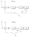
- Figure 1a shows an ideal situation for a closed loop position feedback in an actuator drive control system.
- a power drive 10 drives a motor 12 to move an actuator 14 to position, for example, a nozzle 16.
- a position sensor 18 senses the position of the nozzle 16 and provides a feedback signal 20 to a comparator 22.
- Comparator 22 compares the indicated nozzle position with a desired demand signal 24 and controls the drive 10 accordingly.
- actuator drives may employ the control system shown in Figure 1b
- the position sensor 18 is located on a component of the motor 12 or actuator 14 remote from the nozzle 16. In such circumstances an accurate indication of the position of the nozzle 16 relies on the stiffness of the mechanical components of the actuator 14.
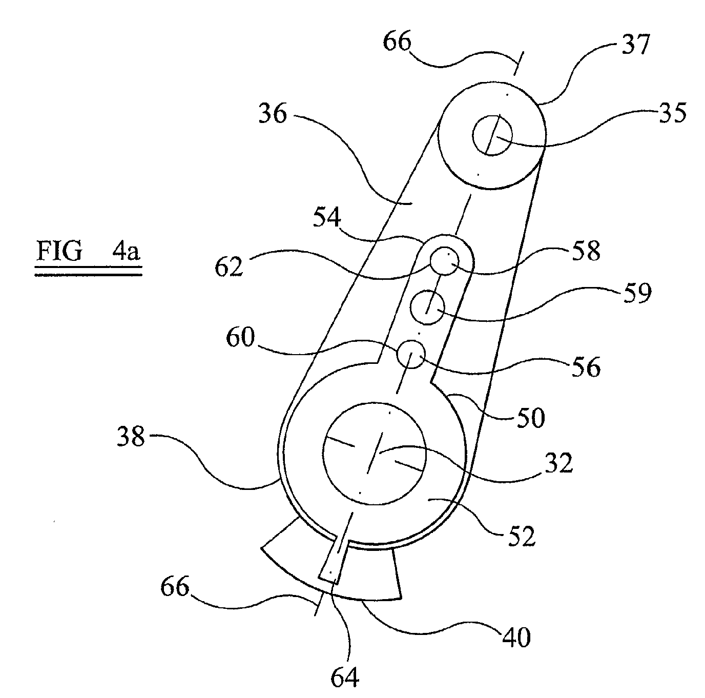
- an angular position of an actuated element in the form of a nozzle 30 is changeable with respect to a pivot point 32 of the nozzle 30 by an actuator mechanism comprising a link 34 and an actuator member in the form of a link arm 36.
- Actuator member 36 is coupled at one end 37 thereof to the link 34 by means of a pinned coupling 35, and engages at an opposite, drive end 38 thereof an output drive shaft of a motor or output shaft of a gearbox (not shown).
- Sensor means in the form of a position sensor 40 comprises a potentiometer having a track 42 and a wiper 44 attached to the actuator member 36.
- torque is applied to the actuator member 36 by the motor so as to rotate the actuator member 36 about the axis 33 of the motor or gearbox output drive shaft.
- the angular position of the actuator member 36 is sensed by the relative positions of the wiper 44 and the track 42 of the position sensor 40.
- the position sensor 40 provides an indication of the position of the end 37 of the actuator member 36.
- the force required to move a nozzle may be large enough to cause a significant deformation of actuator components and a resulting error in the actual position of the nozzle compared with the demanded position.
- the actuator member 36 may bend. Increasing the flexural stiffness of the actuator so as to reduce deformation leads to an increase in weight or restriction of angular travel, which may be undesirable.
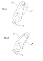
- Figure 3a shows an idealised situation where the actuator member 36 is infinitely stiff.
- a first position 36a is indicated by broken lines and a second position 36b, to which the actuator member 36 has moved under the application of torque in the direction of arrow T, is indicated by the solid lines of the actuator member 36.
- Figure 3b shows a situation where actuator member 36 has a finite stiffness.
- the first position 36a is again indicated by broken lines.
- position 36c the actuator member 36 is shown bending, caused by a reaction force from the nozzle 30 due to resistance of the nozzle 30 to movement.
- the amount of bending is shown in exaggerated form in Figure 3b.
- the position indicated by the position sensor 40 in Figure 3b, when the actuator member is in position 36c, is the same as that in Figure 3a, when the actuator member is in position 36b.
- the nozzle 30 has actually not moved as far as in Figure 3a, and the nozzle 30 is in the same position as it would be for an infinitely stiff actuator member in position 36a.
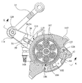
- actuator member 36 is fitted with a marker device 50 comprising an annular portion 52 and an elongate portion 54.
- the annular portion 52 may be a steel ring with an integral slender arm forming the elongate portion 54.
- Location means in the form of a pair of dowel pins 56, 58 is rigidly fixed to the actuator member 36.
- the pins 56, 58 pass through holes 60, 62 in the elongate portion 54 so as to locate the marker device 50 with respect to the actuator member 36.
- Retainer means in the form of a screw 59 passes through a clearance fit hole 63a (visible only in Figure 4b) in the marker device 50 and engages in a threaded hole (not shown, but visible in Figure 7) in the actuator member 36 to prevent the marker device 50 from lifting away from the actuator arm 36.
- An end portion 64 forms a marker and extends from the annular portion 52 of the marker device 50. End portion 64 engages the wiper 44 of the position sensor 40 so as to drive the wiper 44 when the marker device moves.
- the dowel pins 56, 58 are in alignment with an axis 66 passing through a centre of the pinned coupling 35 and the pivot point 32.
- Figure 4b shows the actuator member 36 and marker device 50 in a position where the actuator member 36 is bending.
- the ideal, stiff (i.e. unbent) condition of actuator member 36 is shown by the broken lines 36a.
- the pins 56, 58 may be suitably disposed so as to result in a true indication of the position of the nozzle 16, compensating for deformations in other actuator components, for example the link 34, resulting in a more accurate indication of nozzle position.
- the marker device 50 can thus compensate for deformation of the actuator member 36 and other actuator components so that the position sensor 40 provides a more accurate feedback signal which may be used in closed loop control of the actuator.
- the compensation of the indicated position is a means of providing an apparent high stiffness of the actuator components. Therefore, components having a relatively low stiffness (for example lighter weight components), may be used with fewer associated problems caused by errors in actual position compared with demanded position due to component deformations.
- the exact relationship between the position indicated by the position sensor 40 when the actuator member 36 deforms, and the true position of the nozzle 16 will depend on many factors including the location of the pins 56, 58, the shape and material properties (e.g. flexural stiffness) of the actuator member 36, and the precise mode of deformation, which may be bending or may, for example, include one or a combination of any of bending and elastic tension, compression and shearing. Suitable dispositions of the dowel pins 56, 58 relative to the actuator member 36 may be determined empirically for a given actuator assembly, or may be predicted with the aid of design methods such as stress analysis.
- means other than the dowel pins 56, 58 may be used for securing the marker device to the actuator member 36, and that the location of the securing means does not have to be selected to be in alignment with the longitudinal axis 66.
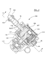
- FIG. 5 shows part of the actuator apparatus, shown generally as 100.
- a drive shaft 102 driven, in use, by a motor (not shown) carries a toothed gear 104 that cooperates with an arrangement of gears 106.
- Gear arrangement 106 comprises planet gear wheels 107 that mesh with internal teeth 108 of an annular gear wheel 110.
- Gear arrangement 106 is housed within a housing 112.
- Annular gear wheel 110 forms part of an actuator member 36 in the form of an annulus arm.
- Actuator member 36 extends through an opening 116 in the housing 112.
- a distal portion 118 of the actuator member 36, external of the housing 112, is connected by means of a pinned joint 120 to link member 34.
- Link member 34 is in turn connected to a nozzle (not shown).
- Annular portion 52 of marker device 50 located within the housing 112, is disposed around the shaft 102 and gear arrangement 106.
- a first annular gap 126 separates the annular portion 52 from the gear arrangement 106.
- a second annular gap 127 separates the annular portion 52 from the housing 112.
- the end portion 64 of the marker device 50 engages a wiper of a position sensor potentiometer 40 for providing a signal indicative of a compensated position.
- Figure 6 shows a view of the actuator apparatus on the section F-F of Figure 5.
- the marker device 50 has an extended portion 54 that extends through the opening 116 in the housing 112.
- the marker device 50 is secured to the actuator member 36 by means of pins 56, 58.
- Pin 58 is not shown in the view of Figure 6 as it is obscured by part of the housing 112, but is shown in Figure 7.
- a screw 59 holds the marker device 50 in position on the actuator arm 36 and pins 56, 58.
- Figure 7 shows an enlarged detail on section K-K of Figure 6.
- the elongate portion 54 of marker device 50 is shown located by the pins 56, 58 and held in place by the screw 59 on the actuator arm 36. Also more clearly shown in Figure 7 are the annular gaps 126, 127 either side of the annular portion 52 of the marker device 50.
- a rotary drive applied to the drive shaft 102 transmits torque through the gear arrangement 106 to the actuator arm 36.
- the torque applied drives the actuator arm 36 in rotation around the axis of drive shaft 102 so as to transmit motion to the link arm 34 to effect a change in position of the nozzle (not shown).
- the change in position of the nozzle, resulting from an angular change in position of the actuator arm 36 causes the marker 64 to move with respect to the potentiometer track 42 so as to provide a signal of the sensed change in position of the nozzle.
- a resistance to movement of the nozzle causes a resistance to the applied torque causing the actuator arm 36 to bend.
- bending of the actuator arm 36 causes a lateral translation of the pins 56, 58 and of the marker device 50.
- the annular portion 52 of the marker device 50 is free to move due to the annular gaps 126, 127 separating it from the gear arrangement 106 and housing 112.
- the lateral translation of the marker device 50 causes an adjustment to the position of the wiper 64 with respect to the track 42 of the potentiometer. This adjustment results in a signal of the sensed change in position of the nozzle that compensates for the bending of the actuator arm 36.
- the marker device 50 may also be used to compensate for lost motion in the actuation system, for example in mechanical components linking the actuator arm 36 to the nozzle.
Landscapes
- Engineering & Computer Science (AREA)
- General Engineering & Computer Science (AREA)
- Mechanical Engineering (AREA)
- Chemical & Material Sciences (AREA)
- Combustion & Propulsion (AREA)
- Transplanting Machines (AREA)
- Control Of Position Or Direction (AREA)
Abstract
Description
Claims (6)
- An actuator apparatus comprising an actuator member (36), and an actuated element (30, 34) movable by actuation of said actuator member (36), the apparatus being characterised by a marker device (50) including a marker (64) the position of which can be sensed in use by sensor means (40), said marker device (50) being secured to said actuator member (36) such that deformation of the actuator member (36) during actuation to move said element (30, 34) causes an adjustment to the change in position of the marker (64).
- Apparatus as claimed in claim 1 characterised in that said actuator member comprises an actuator arm (36) having a longitudinal axis (66), the marker device (50) being secured to the actuator member such that deformation of the actuator arm (36) causes a displacement of the marker device (50) laterally of the longitudinal axis (66) of the actuator arm (36).
- Apparatus as claimed in claim 1 or claim 2 characterised by sensor means (40) for sensing the change in position of said marker (64).
- Apparatus as claimed in claim 3 characterised in that said sensor means (40) includes indicator means for providing an indication of a change of position of said marker (64).
- Apparatus as claimed in any one of claims 1 to 4 characterised in that said marker device (50) is secured to said actuator member such that said adjustment to the change in position of the marker (64) compensates for the deformation of the actuator member and also for deformation of other members of the apparatus.
- Apparatus as claimed in any one of claims 3 to 5 characterised in that said sensor means (40) comprises a potentiometer and the marker is drivingly connected to a wiper (44) of the potentiometer.
Applications Claiming Priority (3)
| Application Number | Priority Date | Filing Date | Title |
|---|---|---|---|
| GB1009038 | 2001-04-10 | ||
| GBGB0109038.0A GB0109038D0 (en) | 2001-04-10 | 2001-04-10 | Actuator apparatus including a marker device |
| GB0109038 | 2001-10-04 |
Publications (3)
| Publication Number | Publication Date |
|---|---|
| EP1275837A2 true EP1275837A2 (en) | 2003-01-15 |
| EP1275837A3 EP1275837A3 (en) | 2004-01-07 |
| EP1275837A9 EP1275837A9 (en) | 2004-05-26 |
Family
ID=9912655
Family Applications (1)
| Application Number | Title | Priority Date | Filing Date |
|---|---|---|---|
| EP02252474A Withdrawn EP1275837A3 (en) | 2001-04-10 | 2002-04-05 | Actuator apparatus including a marker device |
Country Status (3)
| Country | Link |
|---|---|
| US (1) | US6806600B2 (en) |
| EP (1) | EP1275837A3 (en) |
| GB (1) | GB0109038D0 (en) |
Families Citing this family (3)
| Publication number | Priority date | Publication date | Assignee | Title |
|---|---|---|---|---|
| US7647771B2 (en) * | 2005-03-09 | 2010-01-19 | The United States Of America As Represented By The Administrator Of The National Aeronautics And Space Administration | Thermally driven piston assembly and position control therefor |
| US20070243073A1 (en) * | 2006-03-08 | 2007-10-18 | U.S.A. As Represented By The Administrator Of The National Aeronautics And Space Administration | Thermally Driven Piston Assembly And Position Control Therefor |
| US20100252325A1 (en) * | 2009-04-02 | 2010-10-07 | National Oilwell Varco | Methods for determining mechanical specific energy for wellbore operations |
Family Cites Families (8)
| Publication number | Priority date | Publication date | Assignee | Title |
|---|---|---|---|---|
| US2704047A (en) * | 1953-03-05 | 1955-03-15 | Lushenko Gordon | Indicating mechanism for ram operated agricultural tool |
| GB878657A (en) * | 1957-04-22 | 1961-10-04 | Solar Aircraft Co | Improvements relating to gas turbine jet propulsion engines |
| US3825182A (en) * | 1973-05-17 | 1974-07-23 | D Bauchmann | Control devices for dampers and the like |
| US4198921A (en) * | 1978-02-15 | 1980-04-22 | Sparex Ltd. of Exeter Airport | Fluid pressure actuators indicator |
| US4482847A (en) * | 1983-02-25 | 1984-11-13 | Johnson Service Company | Electrically-controlled rotary actuator |
| US4841209A (en) * | 1987-11-25 | 1989-06-20 | United Technologies Corporation | Actuator control system with displacement sensor fault detection |
| JPH06207804A (en) * | 1993-01-05 | 1994-07-26 | Micro Tec:Kk | Position detector for linearly movable actuator |
| US6703742B1 (en) * | 1998-12-15 | 2004-03-09 | Adam K. Brandley | Electric motor with rotor being a drive wheel |
-
2001
- 2001-04-10 GB GBGB0109038.0A patent/GB0109038D0/en not_active Ceased
-
2002
- 2002-04-05 EP EP02252474A patent/EP1275837A3/en not_active Withdrawn
- 2002-04-10 US US10/120,088 patent/US6806600B2/en not_active Expired - Lifetime
Also Published As
| Publication number | Publication date |
|---|---|
| GB0109038D0 (en) | 2001-05-30 |
| EP1275837A9 (en) | 2004-05-26 |
| US20030067229A1 (en) | 2003-04-10 |
| EP1275837A3 (en) | 2004-01-07 |
| US6806600B2 (en) | 2004-10-19 |
Similar Documents
| Publication | Publication Date | Title |
|---|---|---|
| US7407208B2 (en) | Joint drive mechanism and robot hand | |
| US7788921B2 (en) | Shape memory alloy actuator | |
| CN107848122B (en) | Robot with force measuring device | |
| US6273681B1 (en) | Rotor blade flap driving apparatus | |
| US7872397B2 (en) | Electrical to mechanical energy converter | |
| US20030024760A1 (en) | Apparatus and method for steering a vehicle | |
| EP1559630A2 (en) | Apparatus for steering a vehicle | |
| KR20170139606A (en) | Tensioners for operating elements, their associated remote actuating devices, systems and methods | |
| CN108603772B (en) | Rotary structures, assistance systems and robots | |
| US8464842B2 (en) | Brake wear measurement system and method | |
| US7293626B2 (en) | Apparatus and method for steering a vehicle | |
| EP3308063A1 (en) | Rotary actuated valve with position indicator | |
| US6806600B2 (en) | Actuator apparatus including a marker device | |
| EP2890527B1 (en) | Variable-stiffness actuator with passive disturbance rejection | |
| KR920000525A (en) | Actuator for Automobile Clutch | |
| US20070261506A1 (en) | Electrically Driven Linear Actuator | |
| US5703553A (en) | Magnetostrictive active strut | |
| US6840886B2 (en) | Method and apparatus for a low cost, high speed, and compact nanometer precision motion stage using friction drive and flexure hinge | |
| EP3018055B1 (en) | Flight control surface actuation system with connecting rod | |
| US8294406B2 (en) | Parallel kinematics micro-positioning system | |
| US6830223B1 (en) | Force sensor rod | |
| JP7589083B2 (en) | ACTUATOR AND METHOD FOR CONTROLLING ACTUATOR | |
| CN221636030U (en) | Compensation device and master manipulator | |
| US11777367B2 (en) | Linear compact electric actuator having a resilient kinematic chain | |
| US20210114722A1 (en) | Line actuators |
Legal Events
| Date | Code | Title | Description |
|---|---|---|---|
| PUAI | Public reference made under article 153(3) epc to a published international application that has entered the european phase |
Free format text: ORIGINAL CODE: 0009012 |
|
| AK | Designated contracting states |
Kind code of ref document: A2 Designated state(s): AT BE CH CY DE DK ES FI FR GB GR IE IT LI LU MC NL PT SE TR |
|
| AX | Request for extension of the european patent |
Free format text: AL;LT;LV;MK;RO;SI |
|
| RAP1 | Party data changed (applicant data changed or rights of an application transferred) |
Owner name: GOODRICH ACTUATION SYSTEMS LTD |
|
| PUAL | Search report despatched |
Free format text: ORIGINAL CODE: 0009013 |
|
| AK | Designated contracting states |
Kind code of ref document: A3 Designated state(s): AT BE CH CY DE DK ES FI FR GB GR IE IT LI LU MC NL PT SE TR |
|
| AX | Request for extension of the european patent |
Extension state: AL LT LV MK RO SI |
|
| RIC1 | Information provided on ipc code assigned before grant |
Ipc: 7F 16H 25/00 B Ipc: 7F 15B 15/28 B Ipc: 7F 02K 1/00 A |
|
| 17P | Request for examination filed |
Effective date: 20040324 |
|
| AKX | Designation fees paid |
Designated state(s): DE ES FR GB IT |
|
| 17Q | First examination report despatched |
Effective date: 20041229 |
|
| STAA | Information on the status of an ep patent application or granted ep patent |
Free format text: STATUS: THE APPLICATION IS DEEMED TO BE WITHDRAWN |
|
| 18D | Application deemed to be withdrawn |
Effective date: 20050509 |