EP1275552A2 - Hydrostatic transmission control system and method for a tractor or utility vehicle - Google Patents
Hydrostatic transmission control system and method for a tractor or utility vehicle Download PDFInfo
- Publication number
- EP1275552A2 EP1275552A2 EP02014766A EP02014766A EP1275552A2 EP 1275552 A2 EP1275552 A2 EP 1275552A2 EP 02014766 A EP02014766 A EP 02014766A EP 02014766 A EP02014766 A EP 02014766A EP 1275552 A2 EP1275552 A2 EP 1275552A2
- Authority
- EP
- European Patent Office
- Prior art keywords
- acceleration
- transmission
- control
- signal
- control system
- Prior art date
- Legal status (The legal status is an assumption and is not a legal conclusion. Google has not performed a legal analysis and makes no representation as to the accuracy of the status listed.)
- Withdrawn
Links
- 230000005540 biological transmission Effects 0.000 title claims abstract description 65
- 230000002706 hydrostatic effect Effects 0.000 title claims abstract description 37
- 238000000034 method Methods 0.000 title claims description 5
- 230000001133 acceleration Effects 0.000 claims abstract description 38
- 230000004044 response Effects 0.000 claims abstract description 13
- 238000006073 displacement reaction Methods 0.000 claims description 9
- 230000008859 change Effects 0.000 claims description 3
- 239000012530 fluid Substances 0.000 description 25
- 238000010586 diagram Methods 0.000 description 4
- 239000000463 material Substances 0.000 description 2
- 238000012986 modification Methods 0.000 description 2
- 230000004048 modification Effects 0.000 description 2
- 230000007935 neutral effect Effects 0.000 description 2
- 230000009467 reduction Effects 0.000 description 2
- 244000025254 Cannabis sativa Species 0.000 description 1
- CRQQGFGUEAVUIL-UHFFFAOYSA-N chlorothalonil Chemical compound ClC1=C(Cl)C(C#N)=C(Cl)C(C#N)=C1Cl CRQQGFGUEAVUIL-UHFFFAOYSA-N 0.000 description 1
- 238000004891 communication Methods 0.000 description 1
- 230000003750 conditioning effect Effects 0.000 description 1
- 230000000881 depressing effect Effects 0.000 description 1
- 238000004513 sizing Methods 0.000 description 1
Images




Classifications
-
- F—MECHANICAL ENGINEERING; LIGHTING; HEATING; WEAPONS; BLASTING
- F16—ENGINEERING ELEMENTS AND UNITS; GENERAL MEASURES FOR PRODUCING AND MAINTAINING EFFECTIVE FUNCTIONING OF MACHINES OR INSTALLATIONS; THERMAL INSULATION IN GENERAL
- F16H—GEARING
- F16H61/00—Control functions within control units of change-speed- or reversing-gearings for conveying rotary motion ; Control of exclusively fluid gearing, friction gearing, gearings with endless flexible members or other particular types of gearing
- F16H61/38—Control of exclusively fluid gearing
- F16H61/40—Control of exclusively fluid gearing hydrostatic
- F16H61/46—Automatic regulation in accordance with output requirements
- F16H61/47—Automatic regulation in accordance with output requirements for achieving a target output speed
-
- B—PERFORMING OPERATIONS; TRANSPORTING
- B60—VEHICLES IN GENERAL
- B60K—ARRANGEMENT OR MOUNTING OF PROPULSION UNITS OR OF TRANSMISSIONS IN VEHICLES; ARRANGEMENT OR MOUNTING OF PLURAL DIVERSE PRIME-MOVERS IN VEHICLES; AUXILIARY DRIVES FOR VEHICLES; INSTRUMENTATION OR DASHBOARDS FOR VEHICLES; ARRANGEMENTS IN CONNECTION WITH COOLING, AIR INTAKE, GAS EXHAUST OR FUEL SUPPLY OF PROPULSION UNITS IN VEHICLES
- B60K17/00—Arrangement or mounting of transmissions in vehicles
- B60K17/04—Arrangement or mounting of transmissions in vehicles characterised by arrangement, location or kind of gearing
- B60K17/10—Arrangement or mounting of transmissions in vehicles characterised by arrangement, location or kind of gearing of fluid gearing
-
- F—MECHANICAL ENGINEERING; LIGHTING; HEATING; WEAPONS; BLASTING
- F16—ENGINEERING ELEMENTS AND UNITS; GENERAL MEASURES FOR PRODUCING AND MAINTAINING EFFECTIVE FUNCTIONING OF MACHINES OR INSTALLATIONS; THERMAL INSULATION IN GENERAL
- F16H—GEARING
- F16H39/00—Rotary fluid gearing using pumps and motors of the volumetric type, i.e. passing a predetermined volume of fluid per revolution
- F16H39/04—Rotary fluid gearing using pumps and motors of the volumetric type, i.e. passing a predetermined volume of fluid per revolution with liquid motor and pump combined in one unit
- F16H39/06—Rotary fluid gearing using pumps and motors of the volumetric type, i.e. passing a predetermined volume of fluid per revolution with liquid motor and pump combined in one unit pump and motor being of the same type
- F16H39/08—Rotary fluid gearing using pumps and motors of the volumetric type, i.e. passing a predetermined volume of fluid per revolution with liquid motor and pump combined in one unit pump and motor being of the same type each with one main shaft and provided with pistons reciprocating in cylinders
- F16H39/10—Rotary fluid gearing using pumps and motors of the volumetric type, i.e. passing a predetermined volume of fluid per revolution with liquid motor and pump combined in one unit pump and motor being of the same type each with one main shaft and provided with pistons reciprocating in cylinders with cylinders arranged around, and parallel or approximately parallel to the main axis of the gearing
- F16H39/14—Rotary fluid gearing using pumps and motors of the volumetric type, i.e. passing a predetermined volume of fluid per revolution with liquid motor and pump combined in one unit pump and motor being of the same type each with one main shaft and provided with pistons reciprocating in cylinders with cylinders arranged around, and parallel or approximately parallel to the main axis of the gearing with cylinders carried in rotary cylinder blocks or cylinder-bearing members
-
- F—MECHANICAL ENGINEERING; LIGHTING; HEATING; WEAPONS; BLASTING
- F16—ENGINEERING ELEMENTS AND UNITS; GENERAL MEASURES FOR PRODUCING AND MAINTAINING EFFECTIVE FUNCTIONING OF MACHINES OR INSTALLATIONS; THERMAL INSULATION IN GENERAL
- F16H—GEARING
- F16H61/00—Control functions within control units of change-speed- or reversing-gearings for conveying rotary motion ; Control of exclusively fluid gearing, friction gearing, gearings with endless flexible members or other particular types of gearing
- F16H61/38—Control of exclusively fluid gearing
- F16H61/40—Control of exclusively fluid gearing hydrostatic
- F16H61/42—Control of exclusively fluid gearing hydrostatic involving adjustment of a pump or motor with adjustable output or capacity
- F16H61/435—Pump capacity control by electric actuators
-
- F—MECHANICAL ENGINEERING; LIGHTING; HEATING; WEAPONS; BLASTING
- F16—ENGINEERING ELEMENTS AND UNITS; GENERAL MEASURES FOR PRODUCING AND MAINTAINING EFFECTIVE FUNCTIONING OF MACHINES OR INSTALLATIONS; THERMAL INSULATION IN GENERAL
- F16H—GEARING
- F16H61/00—Control functions within control units of change-speed- or reversing-gearings for conveying rotary motion ; Control of exclusively fluid gearing, friction gearing, gearings with endless flexible members or other particular types of gearing
- F16H61/38—Control of exclusively fluid gearing
- F16H61/40—Control of exclusively fluid gearing hydrostatic
- F16H61/46—Automatic regulation in accordance with output requirements
-
- B—PERFORMING OPERATIONS; TRANSPORTING
- B60—VEHICLES IN GENERAL
- B60Y—INDEXING SCHEME RELATING TO ASPECTS CROSS-CUTTING VEHICLE TECHNOLOGY
- B60Y2200/00—Type of vehicle
- B60Y2200/20—Off-Road Vehicles
- B60Y2200/22—Agricultural vehicles
-
- B—PERFORMING OPERATIONS; TRANSPORTING
- B60—VEHICLES IN GENERAL
- B60Y—INDEXING SCHEME RELATING TO ASPECTS CROSS-CUTTING VEHICLE TECHNOLOGY
- B60Y2200/00—Type of vehicle
- B60Y2200/20—Off-Road Vehicles
- B60Y2200/22—Agricultural vehicles
- B60Y2200/221—Tractors
-
- F—MECHANICAL ENGINEERING; LIGHTING; HEATING; WEAPONS; BLASTING
- F16—ENGINEERING ELEMENTS AND UNITS; GENERAL MEASURES FOR PRODUCING AND MAINTAINING EFFECTIVE FUNCTIONING OF MACHINES OR INSTALLATIONS; THERMAL INSULATION IN GENERAL
- F16H—GEARING
- F16H59/00—Control inputs to control units of change-speed- or reversing-gearings for conveying rotary motion
- F16H59/02—Selector apparatus
- F16H2059/0221—Selector apparatus for selecting modes, e.g. sport, normal, economy
- F16H2059/0226—Selector apparatus for selecting modes, e.g. sport, normal, economy for selecting particular shift speeds, e.g. a fast shift speed with aggressive gear change
-
- F—MECHANICAL ENGINEERING; LIGHTING; HEATING; WEAPONS; BLASTING
- F16—ENGINEERING ELEMENTS AND UNITS; GENERAL MEASURES FOR PRODUCING AND MAINTAINING EFFECTIVE FUNCTIONING OF MACHINES OR INSTALLATIONS; THERMAL INSULATION IN GENERAL
- F16H—GEARING
- F16H61/00—Control functions within control units of change-speed- or reversing-gearings for conveying rotary motion ; Control of exclusively fluid gearing, friction gearing, gearings with endless flexible members or other particular types of gearing
- F16H61/66—Control functions within control units of change-speed- or reversing-gearings for conveying rotary motion ; Control of exclusively fluid gearing, friction gearing, gearings with endless flexible members or other particular types of gearing specially adapted for continuously variable gearings
- F16H2061/6604—Special control features generally applicable to continuously variable gearings
- F16H2061/6611—Control to achieve a particular driver perception, e.g. for generating a shift shock sensation
-
- F—MECHANICAL ENGINEERING; LIGHTING; HEATING; WEAPONS; BLASTING
- F16—ENGINEERING ELEMENTS AND UNITS; GENERAL MEASURES FOR PRODUCING AND MAINTAINING EFFECTIVE FUNCTIONING OF MACHINES OR INSTALLATIONS; THERMAL INSULATION IN GENERAL
- F16H—GEARING
- F16H61/00—Control functions within control units of change-speed- or reversing-gearings for conveying rotary motion ; Control of exclusively fluid gearing, friction gearing, gearings with endless flexible members or other particular types of gearing
- F16H61/66—Control functions within control units of change-speed- or reversing-gearings for conveying rotary motion ; Control of exclusively fluid gearing, friction gearing, gearings with endless flexible members or other particular types of gearing specially adapted for continuously variable gearings
- F16H61/662—Control functions within control units of change-speed- or reversing-gearings for conveying rotary motion ; Control of exclusively fluid gearing, friction gearing, gearings with endless flexible members or other particular types of gearing specially adapted for continuously variable gearings with endless flexible members
- F16H2061/66204—Control for modifying the ratio control characteristic
- F16H2061/66213—Control for modifying the ratio control characteristic dependent on driver's choice
-
- F—MECHANICAL ENGINEERING; LIGHTING; HEATING; WEAPONS; BLASTING
- F16—ENGINEERING ELEMENTS AND UNITS; GENERAL MEASURES FOR PRODUCING AND MAINTAINING EFFECTIVE FUNCTIONING OF MACHINES OR INSTALLATIONS; THERMAL INSULATION IN GENERAL
- F16H—GEARING
- F16H2302/00—Determining the way or trajectory to new ratio, e.g. by determining speed, torque or time parameters for shift transition
- F16H2302/04—Determining a modus for shifting
-
- F—MECHANICAL ENGINEERING; LIGHTING; HEATING; WEAPONS; BLASTING
- F16—ENGINEERING ELEMENTS AND UNITS; GENERAL MEASURES FOR PRODUCING AND MAINTAINING EFFECTIVE FUNCTIONING OF MACHINES OR INSTALLATIONS; THERMAL INSULATION IN GENERAL
- F16H—GEARING
- F16H59/00—Control inputs to control units of change-speed- or reversing-gearings for conveying rotary motion
- F16H59/14—Inputs being a function of torque or torque demand
- F16H59/18—Inputs being a function of torque or torque demand dependent on the position of the accelerator pedal
Definitions
- the invention relates to utility vehicles for industrial and agricultural use, such as utility tractors. Particularly, the invention relates to transmission control systems for such vehicles. In addition the invention relates to a method for controlling the acceleration aggressiveness of a transmission.
- Typical utility vehicles such as compact tractors, utilize an engine operating substantially at a pre-selected speed that drives a transmission system or drive train that delivers power to one or more driven wheels.
- the transmission system includes a speed controllable transmission component, a gear selection component, and a differential component.
- the speed controllable transmission component can be, for example, a hydrostatic transmission, or a transmission that uses electro-hydraulically controlled forward and reverse clutch packs to initially accelerate the vehicle and to change vehicle direction (hereinafter referred to as a "reverser transmission"), such as a POWRREVERSER transmission incorporated in JOHN DEERE Series 4000 tractors.
- the present inventors have recognized that the desired "aggressiveness" of a vehicle's performance, or rates of acceleration and deceleration in response to operator commands, depends on operator experience, the operating conditions of the vehicle and the work being performed with the vehicle. For example, experienced operators performing material handling work tend to prefer a vehicle that accelerates and decelerates aggressively, and allows quick changes in direction. An operator that is using a vehicle for turf care work would prefer less aggressive accelerations and decelerations to prevent damage to the grass caused by slipping of the vehicle wheels.
- pre-selecting the vehicle performance is commonly done by sizing orifices to control the rate of fluid flow to the servo control system of the hydrostatic transmission or control the rate of fluid flow to clutch packs in the reverser transmission.
- the aggressiveness is commonly controlled by pre-selecting the rate of increase of the electrical control current to electro-hydraulic pressure reducing valves that control swashplate servo systems or clutch pack hydraulic pressures.
- compact utility tractors are commonly used for both material handling and turf care as well as many other operations.
- the object to be met with the invention is to provide a utility tractor that would allow the driver to choose the aggressiveness of the tractor's performance according to the work being done. Such a selectable aggressiveness would lead to improved tractor productivity.
- a vehicle transmission control system includes a controller, operator controlled potentiometers and electro-hydraulic control valves which control hydraulic pressure in the servo control system of the hydrostatic transmission.
- the operator is provided with a two-position set switch.
- the software in the controller provides a a relatively slow current ramp to energize the electro-hydraulic control valves that control the actuation of the servo system of a hydrostatic transmission.
- acceleration is non-aggressive. Decelerations are also performed at a relatively non-aggressive rate.
- the two-position set switch could be replaced with a potentiometer, thus permitting an infinitely variable range in transmission aggressiveness control.
- the operator can choose the acceleration/deceleration rates according to the operator's comfort or skill level and/or to the task being performed.
- the vehicle performance, controllability and productivity will be improved.
- the hydrostatic transmission 26 includes a variable displacement pump 30, and a hydraulic motor 34.
- An engine drive 35 rotationally drives the variable displacement pump 30.
- the hydraulic motor drives the multi-gear transmission drive 27 interposed between the hydraulic motor 34 and the driven wheel 28.
- the control system 16 includes a controller 52, such as a microprocessor-based microcontroller, in signal-communication with an acceleration mode or "aggressiveness" set switch 56.
- the set switch 56 is selectively activated to trigger a more aggressive or a less-aggressive acceleration mode in the controller software, as described hereinafter.
- the controller 52 is signal-connected, through appropriate signal conditioning or amplifying circuitry (not shown), to a solenoid 106a of a forward drive proportional pressure control valve 106 and to a solenoid 108a of a reverse drive proportional pressure control valve 108.
- the output current to energize the forward or reverse pressure control valves 106, 108 is substantially proportional to the corresponding pedal position signal.
- An adjustable profile can be used to give the pedal a non-linear response to increase vehicle drivability.
- the selectable ramps of the output current from the controller 52 control the rate of acceleration and deceleration of the vehicle.
- Two different programmed parameter sets in the controller software provide for a more aggressive operating mode and a less aggressive operating mode.
- the operator-activated set switch 56 is used to select between the two operating modes.
- the parameter sets can become effective by switching to the desired operating mode without returning the foot pedals 72, 74 to neutral.
- FIGS 2 and 3 illustrate the hydrostatic transmission servo control in more detail.
- the hydrostatic transmission provides infinitely variable speed control, forward and reverse, by operation of the foot pedals 72, 74.
- Each valve 106, 108 is connected to a source of pressurized hydraulic fluid S and a return channel R at a reduced pressure.
- the return channel R recirculates hydraulic fluid back to the vehicle's hydraulic system reservoir.
- Depressing the forward foot pedal 72 causes an electrical output signal or voltage of the potentiometer 82 to be transmitted to the controller 52.
- the controller 52 through software, generates a pre-selected current ramp output, having a current vs. time profile selected by position of the set switch 56, to energize the solenoid driver 106a of the forward drive proportional valve 106.
- the proportional valve 106 is opened according to the ramp output, allowing pressurized hydraulic fluid, fed from the source S into the inlet 107 of the valve 106, to flow through the valve 106 to pressurize a servo cylinder 114 on one side of a servo piston 112 that is slidably housed in the cylinder 114.
- the other valve 108 allows fluid to flow from within the cylinder 114, from an opposite side of the servo piston 112, to the return channel R.
- the piston 112 has a notch 115 that holds a piston follower 116 ( Figure 3).
- the piston follower 116 controls movement of a variable displacement pump cam plate or swashplate 118. Movement of the piston 112 causes the cam plate118 in the hydraulic pump to rotate out of the neutral position. Maximum displacement of the pump 30 is attained when the servo piston 112 is moved to its extreme position.
- the swashplate 118 attains a range of forward positions selected by the foot pedal 72.
- the potentiometer 84 sends an electrical output signal or voltage to the controller 52.
- the controller 52 through software, generates a pre-selected current output ramp, having a current vs. time profile selected by position of the set switch 56, to energize the solenoid 108a of the reverse drive proportional valve 108.
- the reverse drive proportional valve 108 is opened, according to the ramp output, to allow pressurized hydraulic fluid, fed into an inlet 119 of the valve 108 from the source S, to flow through the valve 108 to pressurize the servo cylinder 114 on an opposite side of the servo piston 112 within the cylinder 114.
- the other valve 106 allows fluid to flow from within the cylinder 114, from the one side of the servo piston 112, to the return channel R.
- the controller 52 modulates the deceleration command according to a preselected current output ramps to the respective control valve solenoids 106a, 108a in a similar, but reversed, fashion as described for acceleration, based on the respective pedal position signal from the respective potentiometers 82, 84 and the selected current ramp profile from the set switch 56.
- the solenoid 106a includes a plunger 120 (shown schematically) driven by the solenoid coil 121 (shown schematically).
- the plunger 120 drives a valve spool 122 within a housing 123.
- the housing provides the pressurized hydraulic fluid inlet 107, in the form of plural openings, and an outlet 124, in the form of plural openings, to the hydraulic fluid reservoir.
- a control pressure outlet 125 communicates hydraulic fluid at a modulated pressure to the servo cylinder 114 as shown in Figure 2.
- the solenoid coil 121 drives the plunger 120 downward (in Figure 3A) to open the inlet 107 to the outlet 125 through an annular channel 122a.
- the channel 122a is open to an oblong orifice 122b through the spool 122 to communicate fluid into an interior 122c of the spool.
- the interior of the spool is open to the outlet 125.
- the pressure of the hydraulic fluid at the control outlet 125 is substantially proportional to the force applied to the spool by the plunger, ranging between reservoir pressure, the pressure at the outlet 125 with the inlet 107 closed, as shown in Figure 3A, to pressurized hydraulic fluid supply pressure, the spool 122 moved down to close the outlet 124 and open the inlet 107.
- the control valve 108 can be identically configured as described above for the control valve 106.
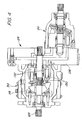
- FIG. 4 illustrates the hydrostatic transmission 26 in more detail.
- the hydrostatic pump 30 illustrated is an axial piston, servo controlled, variable displacement piston pump.
- Input shaft splines 126 are driven via a flex plate (not shown) bolted onto the engine flywheel (not shown).
- Fluid flow through the pump 30 is controlled by changing the angle of the swashplate 118.
- the servo piston 112 controls this angle.
- Moving the respective directional pedal 72, 74 controls the valves 106, 108 via the controller software to provide a hydraulic assist to the double acting piston 112 which controls the position of the swashplate 118.
- the location, off center, of the swashplate controls the distance the pistons 130 travel inside the piston bores 132 of the rotating assembly.
- the direction that the cam plate is rotated from center determines the direction of fluid flow (forward or reverse).
- the number of degrees the cam plate is deflected determines how much fluid will be displaced, i.e. determines the transmission speed.
- the hydrostatic pump 30 provides hydraulic fluid to the hydrostatic motor 34 through the back plate 138. Hydraulic fluid in the power train circulates in a closed loop. Fluid leaves the hydrostatic pump 30, flows through the hydrostatic motor 34, and is returned to the hydrostatic pump. Fluid that leaves this closed loop circuit, such as to the case drain, is replenished by fluid from the charge pump.
- the hydrostatic motor 34 is a high torque axial piston motor.
- the motor is located on the rear of the back plate.
- the hydrostatic motor drives an output shaft coupled to the range transmission 27 that transfers power to the wheels.
- the range transmission 27 can be a multi-speed range gear transmission, such as a three-speed or four-speed gearbox.
- Figure 5 presents a comparison between a less aggressive power control and a more aggressive power control.
- a 100 percent drive command corresponding to full pedal depression, either forward pedal 72 or reverse pedal 74 results in a proportional hydraulic pressure, controlled by the software of the controller 52 and the respective control valve 106,108, in the servo cylinder 114, of the hydrostatic transmission, within one second.
- 100 percent of the drive command results in a corresponding hydraulic pressure, controlled by the software of the controller 52 and the respective control valve 106,108, in the servo cylinder 114 of the hydrostatic transmission, within two seconds.
- Figure 6 illustrates that for the hydrostatic transmission control described in Figure 1, the controller 52 and the respective control valve 106,108 also modulate decelerations for both forward and reverse operation.
- the software of the controller 52 and the respective control valve 106,108 cause a 100 percent deceleration command by the foot pedal position signal, to be realized in a corresponding hydraulic pressure reduction in the servo cylinder 114 of the hydrostatic transmission, within one second.
- the software of the controller 52, and the respective control valve 106,108 cause a 100 percent deceleration command by the foot pedal position signal to be realized in a corresponding hydraulic pressure reduction in the servo cylinder 114 of the hydrostatic transmission, within two seconds.
Landscapes
- Engineering & Computer Science (AREA)
- General Engineering & Computer Science (AREA)
- Mechanical Engineering (AREA)
- Chemical & Material Sciences (AREA)
- Combustion & Propulsion (AREA)
- Transportation (AREA)
- Control Of Fluid Gearings (AREA)
Abstract
Description
- The invention relates to utility vehicles for industrial and agricultural use, such as utility tractors. Particularly, the invention relates to transmission control systems for such vehicles. In addition the invention relates to a method for controlling the acceleration aggressiveness of a transmission.
- Typical utility vehicles, such as compact tractors, utilize an engine operating substantially at a pre-selected speed that drives a transmission system or drive train that delivers power to one or more driven wheels. The transmission system includes a speed controllable transmission component, a gear selection component, and a differential component. The speed controllable transmission component can be, for example, a hydrostatic transmission, or a transmission that uses electro-hydraulically controlled forward and reverse clutch packs to initially accelerate the vehicle and to change vehicle direction (hereinafter referred to as a "reverser transmission"), such as a POWRREVERSER transmission incorporated in JOHN DEERE Series 4000 tractors.
- The present inventors have recognized that the desired "aggressiveness" of a vehicle's performance, or rates of acceleration and deceleration in response to operator commands, depends on operator experience, the operating conditions of the vehicle and the work being performed with the vehicle. For example, experienced operators performing material handling work tend to prefer a vehicle that accelerates and decelerates aggressively, and allows quick changes in direction. An operator that is using a vehicle for turf care work would prefer less aggressive accelerations and decelerations to prevent damage to the grass caused by slipping of the vehicle wheels.
- For hydrostatic transmissions and reverser transmissions, pre-selecting the vehicle performance is commonly done by sizing orifices to control the rate of fluid flow to the servo control system of the hydrostatic transmission or control the rate of fluid flow to clutch packs in the reverser transmission. With electronically controlled systems, the aggressiveness is commonly controlled by pre-selecting the rate of increase of the electrical control current to electro-hydraulic pressure reducing valves that control swashplate servo systems or clutch pack hydraulic pressures.
- However, compact utility tractors are commonly used for both material handling and turf care as well as many other operations. The object to be met with the invention is to provide a utility tractor that would allow the driver to choose the aggressiveness of the tractor's performance according to the work being done. Such a selectable aggressiveness would lead to improved tractor productivity.
- The present invention provides for operator selection of vehicle "aggressiveness," or rates of acceleration in response to operator command. The aggressiveness of a vehicle's performance can be controlled by modulating control signals to control valves, control valves which determine the acceleration of the vehicle transmission, according to two or more electrical ramp-up (or ramp-down) profiles, in response to an operator's acceleration command (or deceleration command).
- According to the preferred embodiment of the present invention, a vehicle transmission control system includes a controller, operator controlled potentiometers and electro-hydraulic control valves which control hydraulic pressure in the servo control system of the hydrostatic transmission.
- The operator is provided with a two-position set switch. With the set switch in the less aggressive position, in response to an operator's command, the software in the controller provides a a relatively slow current ramp to energize the electro-hydraulic control valves that control the actuation of the servo system of a hydrostatic transmission. By ramping up the hydraulic pressure slowly, in response to the slow current ramps, acceleration is non-aggressive. Decelerations are also performed at a relatively non-aggressive rate.
- The selective aggressiveness function is operable for both forward and reverse operation.
- With the switch in the more aggressive position, the current ramps and resultant pressure ramps are faster, thus causing more aggressive transmission operation for the hydrostatic transmission. Decelerations for the hydrostatic transmission are also more aggressive.
- The two-position set switch could be replaced with a potentiometer, thus permitting an infinitely variable range in transmission aggressiveness control.
- By providing the tractor operator with selectable transmission aggressiveness, the operator can choose the acceleration/deceleration rates according to the operator's comfort or skill level and/or to the task being performed. The vehicle performance, controllability and productivity will be improved.
- Numerous other advantages and features of the present invention will become readily apparent from the following detailed description of the invention and the embodiments thereof, from the claims and from the accompanying drawings.
-
- Figure 1
- is a block diagram of the control system of the present invention applied to a hydrostatic transmission system;
- Figure 2
- is a schematic sectional view of the servo control system used in a hydrostatic transmission of Figure 1;
- Figure 3
- is an exploded, fragmentary perspective view of the servo control system of Figure 2;
- Figure 3A
- is a schematic sectional view of a control valve of the system of Figure 3;
- Figure 4
- is a schematic sectional view of a hydrostatic transmission;
- Figure 5
- is a diagram demonstrating the two aggressiveness settings and the time response of hydrostatic transmission servo system hydraulic pressure as a percentage of the total drive command hydraulic pressure, for accelerations; and
- Figure 6
- is a diagram demonstrating the two aggressiveness settings and the time response of hydrostatic transmission servo system hydraulic pressure as a percentage of the total drive command hydraulic pressure, for decelerations.
- While this invention is susceptible of embodiment in many different forms, there are shown in the drawings, and will be described herein in detail, specific embodiments thereof with the understanding that the present disclosure is to be considered as an exemplification of the principles of the invention and is not intended to limit the invention to the specific embodiments illustrated.
- Figure 1 illustrates, in block diagram form, a
vehicle 12 incorporating a first embodimentdrive control system 16 of the present invention. The vehicle incorporates ahydrostatic transmission 26 and a range gear drive, such as amulti-speed gear transmission 27, for transmitting power through a differential (not shown) to one or more drivenwheels 28. - The
hydrostatic transmission 26 includes avariable displacement pump 30, and ahydraulic motor 34. Anengine drive 35 rotationally drives thevariable displacement pump 30. The hydraulic motor drives themulti-gear transmission drive 27 interposed between thehydraulic motor 34 and the drivenwheel 28. - The
control system 16 includes acontroller 52, such as a microprocessor-based microcontroller, in signal-communication with an acceleration mode or "aggressiveness"set switch 56. Theset switch 56 is selectively activated to trigger a more aggressive or a less-aggressive acceleration mode in the controller software, as described hereinafter. - The
control system 16 includes aforward pedal 72 and areverse pedal 74. Theforward pedal 72 is operatively engaged with apotentiometer 82 to produce a forward pedal position signal, and areverse pedal 74 is operatively engaged with apotentiometer 84 to produce a reverse pedal position signal. Thepotentiometers controller 52. - The
controller 52 is signal-connected, through appropriate signal conditioning or amplifying circuitry (not shown), to asolenoid 106a of a forward drive proportionalpressure control valve 106 and to asolenoid 108a of a reverse drive proportionalpressure control valve 108. The output current to energize the forward or reversepressure control valves - The selectable ramps of the output current from the
controller 52 control the rate of acceleration and deceleration of the vehicle. Two different programmed parameter sets in the controller software provide for a more aggressive operating mode and a less aggressive operating mode. The operator-activatedset switch 56 is used to select between the two operating modes. The parameter sets can become effective by switching to the desired operating mode without returning thefoot pedals - Figures 2 and 3 illustrate the hydrostatic transmission servo control in more detail. Given an engine drive speed and a range transmission or gear transmission gear selection, the hydrostatic transmission provides infinitely variable speed control, forward and reverse, by operation of the
foot pedals valve - Depressing the
forward foot pedal 72 causes an electrical output signal or voltage of thepotentiometer 82 to be transmitted to thecontroller 52. Thecontroller 52, through software, generates a pre-selected current ramp output, having a current vs. time profile selected by position of theset switch 56, to energize thesolenoid driver 106a of the forward driveproportional valve 106. Theproportional valve 106 is opened according to the ramp output, allowing pressurized hydraulic fluid, fed from the source S into theinlet 107 of thevalve 106, to flow through thevalve 106 to pressurize aservo cylinder 114 on one side of aservo piston 112 that is slidably housed in thecylinder 114. Theother valve 108 allows fluid to flow from within thecylinder 114, from an opposite side of theservo piston 112, to the return channel R. - The
piston 112 has anotch 115 that holds a piston follower 116 (Figure 3). Thepiston follower 116 controls movement of a variable displacement pump cam plate orswashplate 118. Movement of thepiston 112 causes the cam plate118 in the hydraulic pump to rotate out of the neutral position. Maximum displacement of thepump 30 is attained when theservo piston 112 is moved to its extreme position. Theswashplate 118 attains a range of forward positions selected by thefoot pedal 72. - When the
reverse pedal 74 is pressed, thepotentiometer 84 sends an electrical output signal or voltage to thecontroller 52. Thecontroller 52, through software, generates a pre-selected current output ramp, having a current vs. time profile selected by position of theset switch 56, to energize thesolenoid 108a of the reverse driveproportional valve 108. The reverse driveproportional valve 108 is opened, according to the ramp output, to allow pressurized hydraulic fluid, fed into aninlet 119 of thevalve 108 from the source S, to flow through thevalve 108 to pressurize theservo cylinder 114 on an opposite side of theservo piston 112 within thecylinder 114. Theother valve 106 allows fluid to flow from within thecylinder 114, from the one side of theservo piston 112, to the return channel R. - Preferably, the
valve solenoids - When either the forward or reverse
pedals controller 52 modulates the deceleration command according to a preselected current output ramps to the respectivecontrol valve solenoids respective potentiometers set switch 56. - The hydrostatic system is preferably a closed loop fluid power system that consists of a charge pump (not shown), and the
variable displacement pump 30, which is driven by a flex plate/dampener assembly (not shown) connected to the flywheel. The charge pump provides pressurized fluid to the proportional valve inlets 107,119. Return fluid from the servo control unit is routed to the reservoir of the vehicle's hydraulic system. - An exemplary example of a control valve, such as the
control valve 106, is illustrated in Figure 3A. Thesolenoid 106a includes a plunger 120 (shown schematically) driven by the solenoid coil 121 (shown schematically). Theplunger 120 drives avalve spool 122 within ahousing 123. The housing provides the pressurized hydraulicfluid inlet 107, in the form of plural openings, and anoutlet 124, in the form of plural openings, to the hydraulic fluid reservoir. Acontrol pressure outlet 125 communicates hydraulic fluid at a modulated pressure to theservo cylinder 114 as shown in Figure 2. Thesolenoid coil 121 drives theplunger 120 downward (in Figure 3A) to open theinlet 107 to theoutlet 125 through an annular channel 122a. - The channel 122a is open to an
oblong orifice 122b through thespool 122 to communicate fluid into an interior 122c of the spool. The interior of the spool is open to theoutlet 125. The pressure of the hydraulic fluid at thecontrol outlet 125 is substantially proportional to the force applied to the spool by the plunger, ranging between reservoir pressure, the pressure at theoutlet 125 with theinlet 107 closed, as shown in Figure 3A, to pressurized hydraulic fluid supply pressure, thespool 122 moved down to close theoutlet 124 and open theinlet 107. - An annular screen 107a and a
circular screen 125a can be supplied to theinlet 107 and to theoutlet 125 respectively. - The
control valve 108 can be identically configured as described above for thecontrol valve 106. - Figure 4 illustrates the
hydrostatic transmission 26 in more detail. Thehydrostatic pump 30 illustrated is an axial piston, servo controlled, variable displacement piston pump. Input shaft splines 126 are driven via a flex plate (not shown) bolted onto the engine flywheel (not shown). - Fluid flow through the
pump 30 is controlled by changing the angle of theswashplate 118. Theservo piston 112 controls this angle. Moving the respectivedirectional pedal valves double acting piston 112 which controls the position of theswashplate 118. - The location, off center, of the swashplate controls the distance the
pistons 130 travel inside the piston bores 132 of the rotating assembly. The direction that the cam plate is rotated from center determines the direction of fluid flow (forward or reverse). The number of degrees the cam plate is deflected determines how much fluid will be displaced, i.e. determines the transmission speed. - The
hydrostatic pump 30 provides hydraulic fluid to thehydrostatic motor 34 through theback plate 138. Hydraulic fluid in the power train circulates in a closed loop. Fluid leaves thehydrostatic pump 30, flows through thehydrostatic motor 34, and is returned to the hydrostatic pump. Fluid that leaves this closed loop circuit, such as to the case drain, is replenished by fluid from the charge pump. - The
hydrostatic motor 34 is a high torque axial piston motor. The motor is located on the rear of the back plate. The hydrostatic motor drives an output shaft coupled to therange transmission 27 that transfers power to the wheels. Therange transmission 27 can be a multi-speed range gear transmission, such as a three-speed or four-speed gearbox. - Figure 5 presents a comparison between a less aggressive power control and a more aggressive power control. As an example, for the more aggressive setting of the
set switch 56, a 100 percent drive command corresponding to full pedal depression, eitherforward pedal 72 orreverse pedal 74, results in a proportional hydraulic pressure, controlled by the software of thecontroller 52 and the respective control valve 106,108, in theservo cylinder 114, of the hydrostatic transmission, within one second. For the less aggressive setting, 100 percent of the drive command results in a corresponding hydraulic pressure, controlled by the software of thecontroller 52 and the respective control valve 106,108, in theservo cylinder 114 of the hydrostatic transmission, within two seconds. - Figure 6 illustrates that for the hydrostatic transmission control described in Figure 1, the
controller 52 and the respective control valve 106,108 also modulate decelerations for both forward and reverse operation. For a more aggressive modulation setting of theset switch 56, the software of thecontroller 52 and the respective control valve 106,108 cause a 100 percent deceleration command by the foot pedal position signal, to be realized in a corresponding hydraulic pressure reduction in theservo cylinder 114 of the hydrostatic transmission, within one second. For a less aggressive modulation setting of theset switch 56, the software of thecontroller 52, and the respective control valve 106,108, cause a 100 percent deceleration command by the foot pedal position signal to be realized in a corresponding hydraulic pressure reduction in theservo cylinder 114 of the hydrostatic transmission, within two seconds. - From the foregoing, it will be observed that numerous variations and modifications may be effected without departing from the spirit and scope of the invention. It is to be understood that no limitation with respect to the specific apparatus illustrated herein is intended or should be inferred. It is, of course, intended to cover by the appended claims all such modifications as fall within the scope of the claims.
Claims (10)
- A vehicle control system (16) comprising: a control; an accelerator activated by a user to send an acceleration demand signal to said control; said control having an acceleration circuit receiving said acceleration demand signal and producing a selectable output signal proportional to said demand signal selectable between a first output signal and a second, greater output signal; an operator controlled selector for selecting between said first and second output signals; a transmission arranged for directing power to a wheel, said transmission responsive to said selectable output signal to accelerate said wheel (28).
- The control system according to claim 1, characterized in that said control comprises a microcontroller (52).
- The control system according to claim 1 or 2, characterized in that said transmission comprises a hydrostatic transmission (26) having a variable displacement pump (30) controlled by at least one proportional control valve (106, 108), said output signal controlling said proportional control valve (106, 108).
- The control system according to one or several of the previous claims, characterized in that said acceleration demand signal comprises an electric signal proportional to accelerator travel.
- The control system according to one or several of the previous claims, characterized in that said accelerator includes a potentiometer (82, 84) for providing said input signal, said input signal proportional to accelerator travel.
- A vehicle control system (16) comprising: a controller (52) having a programmed acceleration circuitry; at least a forward acceleration pedal (72) having a position sensor, preferably a potentiometer (82, 84), that is signal-connected to an input of said programmed acceleration circuitry in the controller (52); at least one electrically controlled hydraulic proportional control valve (106, 108) that is signal-connected to said programmed acceleration circuitry of the controller (52); a transmission responsive to said hydraulic proportional control valve (106, 108) to drive a wheel (28); said programmed acceleration circuitry includes a first programmed electric current control circuit having as a first output signal a first rate of change of electric current over time in response to said input from said position sensor; said programmed acceleration circuitry includes a second electric current control circuitry having as a second output signal a second rate of change of electric current over time in response to said input from said position sensor; a selection device, preferably a switch (56), for operator selection between said first and second electric current control circuits; and said control valve proportionally responsive to a selected one of said first and second output signals.
- The control system according to claim 6, wherein said transmission comprises a variable displacement pump (30) having a swashplate (118), the angular position of the swashplate (118) controlling variable displacement pump capacity, the pump (30) hydraulically connected to a hydraulic motor (34), and said proportional control valve (106, 108) controls swashplate (118) angular position.
- A method of controlling the acceleration aggressiveness of a transmission, comprising the steps of: obtaining an input signal from an accelerator proportional to acceleration demand; selecting one out of at least a first and a second acceleration function, each producing an output signal proportional to the input signal, said first acceleration function producing, a first output signal and said second acceleration function producing a second, greater output signal; said output signal being signal-connected to a transmission hydraulic control valve (106, 108) to control acceleration of said transmission.
- The method according to claim 8, characterized in that said step of selecting one acceleration function is further defined in that said one acceleration function is selected from an infinite number of acceleration functions selectable by a potentiometer (82, 84).
- The method according to claim 8 or 9, characterized in that said step of selecting one acceleration function is further defined in that said acceleration function is selectable between said first and second acceleration functions alternatively by a switch (56).
Applications Claiming Priority (2)
| Application Number | Priority Date | Filing Date | Title |
|---|---|---|---|
| US905260 | 1978-05-12 | ||
| US09/905,260 US20030010026A1 (en) | 2001-07-13 | 2001-07-13 | Hydrostatic transmission control system having aggressive and non-aggressive modes |
Publications (2)
| Publication Number | Publication Date |
|---|---|
| EP1275552A2 true EP1275552A2 (en) | 2003-01-15 |
| EP1275552A3 EP1275552A3 (en) | 2005-05-25 |
Family
ID=25420507
Family Applications (1)
| Application Number | Title | Priority Date | Filing Date |
|---|---|---|---|
| EP02014766A Withdrawn EP1275552A3 (en) | 2001-07-13 | 2002-07-04 | Hydrostatic transmission control system and method for a tractor or utility vehicle |
Country Status (3)
| Country | Link |
|---|---|
| US (1) | US20030010026A1 (en) |
| EP (1) | EP1275552A3 (en) |
| CA (1) | CA2392796A1 (en) |
Cited By (7)
| Publication number | Priority date | Publication date | Assignee | Title |
|---|---|---|---|---|
| EP1795784A2 (en) | 2005-12-09 | 2007-06-13 | Deere & Company | Tractor having a hydrostatic transmission and method of operating a hydrostatic transmission on a tractor |
| WO2008054587A1 (en) * | 2006-10-31 | 2008-05-08 | Caterpillar Inc. | Operator interface for torque controlled transmission |
| WO2009045284A3 (en) * | 2007-09-28 | 2009-12-03 | Caterpillar Inc. | Torque-based control system for a continuously variable transmission |
| EP2256379A3 (en) * | 2009-05-20 | 2012-03-21 | CNH Belgium N.V. | Hydrostatic ground drive control system for a work machine with smooth transition between speed ranges |
| US10440880B2 (en) | 2007-09-11 | 2019-10-15 | Hydro-Gear Limited Partnership | Control systems and methods for electric drive utility vehicles |
| EP3109091B1 (en) * | 2007-09-11 | 2021-11-10 | Hydro-Gear Limited Partnership | Control systems and methods for electric drive utility vehicles |
| EP4372248A1 (en) * | 2022-11-17 | 2024-05-22 | Kubota Corporation | Work vehicle |
Families Citing this family (11)
| Publication number | Priority date | Publication date | Assignee | Title |
|---|---|---|---|---|
| US7104036B2 (en) * | 2004-10-29 | 2006-09-12 | Deere & Company | Reverse implement option using reverse pedal |
| US7316115B1 (en) | 2005-01-05 | 2008-01-08 | Sauer-Danfoss Inc. | Means and method for controlling a hydromechanical transmission in dual mode |
| US7926267B2 (en) * | 2008-03-20 | 2011-04-19 | Caterpillar Inc. | Hystat transmission having pressure override control |
| WO2011087938A2 (en) * | 2010-01-15 | 2011-07-21 | Borgwarner Inc. | Solenoid with plastic sleeve using a series of metal components as bearing surfaces |
| US9371898B2 (en) * | 2012-12-21 | 2016-06-21 | Cnh Industrial America Llc | Control system for a machine with a dual path electronically controlled hydrostatic transmission |
| US9599107B2 (en) * | 2013-02-22 | 2017-03-21 | Cnh Industrial America Llc | System and method for controlling a hydrostatic drive unit of a work vehicle using a combination of closed-loop and open-loop control |
| US9309969B2 (en) * | 2013-02-22 | 2016-04-12 | Cnh Industrial America Llc | System and method for controlling a hydrostatic drive unit of a work vehicle |
| US9423026B2 (en) | 2013-12-20 | 2016-08-23 | Cnh Industrial America Llc | System and method for controlling a continuously variable transmission when transitioning operation from a hydrostatic mode to a hydro-mechanical mode |
| DE102017131133B4 (en) * | 2017-12-22 | 2019-08-14 | Hubtex Maschinenbau Gmbh & Co. Kg | Operating method of a person-controlled industrial truck and industrial truck |
| US10696327B2 (en) * | 2018-10-26 | 2020-06-30 | Danfoss Power Solutions Inc. | Electronic pressure limiting for dual path systems |
| US12222033B2 (en) | 2022-10-24 | 2025-02-11 | Deere & Company | Hydrostatic transmission control system |
Family Cites Families (5)
| Publication number | Priority date | Publication date | Assignee | Title |
|---|---|---|---|---|
| JPH0686193B2 (en) * | 1989-03-22 | 1994-11-02 | 本田技研工業株式会社 | Continuously variable transmission with throttle control |
| JPH04357366A (en) * | 1991-06-03 | 1992-12-10 | Toyota Autom Loom Works Ltd | Engine vehicle provided with variable speed and capacity hydraulic pump |
| JP2752012B2 (en) * | 1991-06-14 | 1998-05-18 | 本田技研工業株式会社 | Shift control method for continuously variable transmission for vehicle |
| DE19524669C2 (en) * | 1995-07-06 | 1999-03-18 | Sauer Sundstrand Gmbh & Co | Control and regulating device for commissioning a vehicle with an automotive hydrostatic transmission |
| DE19732369B4 (en) * | 1997-07-28 | 2007-02-15 | Volkswagen Ag | Method for controlling an automatic transmission and a switching device for selecting the driving strategies |
-
2001
- 2001-07-13 US US09/905,260 patent/US20030010026A1/en not_active Abandoned
-
2002
- 2002-07-04 EP EP02014766A patent/EP1275552A3/en not_active Withdrawn
- 2002-07-09 CA CA002392796A patent/CA2392796A1/en not_active Abandoned
Non-Patent Citations (1)
| Title |
|---|
| None |
Cited By (9)
| Publication number | Priority date | Publication date | Assignee | Title |
|---|---|---|---|---|
| EP1795784A2 (en) | 2005-12-09 | 2007-06-13 | Deere & Company | Tractor having a hydrostatic transmission and method of operating a hydrostatic transmission on a tractor |
| EP1795784A3 (en) * | 2005-12-09 | 2010-06-02 | Deere & Company | Tractor having a hydrostatic transmission and method of operating a hydrostatic transmission on a tractor |
| WO2008054587A1 (en) * | 2006-10-31 | 2008-05-08 | Caterpillar Inc. | Operator interface for torque controlled transmission |
| US10440880B2 (en) | 2007-09-11 | 2019-10-15 | Hydro-Gear Limited Partnership | Control systems and methods for electric drive utility vehicles |
| EP3109091B1 (en) * | 2007-09-11 | 2021-11-10 | Hydro-Gear Limited Partnership | Control systems and methods for electric drive utility vehicles |
| WO2009045284A3 (en) * | 2007-09-28 | 2009-12-03 | Caterpillar Inc. | Torque-based control system for a continuously variable transmission |
| US8216109B2 (en) | 2007-09-28 | 2012-07-10 | Caterpillar Inc. | Torque-based control system for a continuously variable transmission |
| EP2256379A3 (en) * | 2009-05-20 | 2012-03-21 | CNH Belgium N.V. | Hydrostatic ground drive control system for a work machine with smooth transition between speed ranges |
| EP4372248A1 (en) * | 2022-11-17 | 2024-05-22 | Kubota Corporation | Work vehicle |
Also Published As
| Publication number | Publication date |
|---|---|
| US20030010026A1 (en) | 2003-01-16 |
| CA2392796A1 (en) | 2003-01-13 |
| EP1275552A3 (en) | 2005-05-25 |
Similar Documents
| Publication | Publication Date | Title |
|---|---|---|
| EP1277992B1 (en) | Speed control for a utility vehicle | |
| CA2392790C (en) | Operator selected maximum speed and recalibrated pedal range for a vehicle | |
| EP1275552A2 (en) | Hydrostatic transmission control system and method for a tractor or utility vehicle | |
| EP1275887B1 (en) | Anti-stall transmission control for utility vehicle | |
| US6851495B2 (en) | Speed control for utility vehicle operable from rearward-facing seat | |
| EP1304509B1 (en) | Control system for reverser transmission | |
| US9096230B2 (en) | Hystat drive system having coasting functionality | |
| WO2002021023A1 (en) | Speed controller of wheel type hydraulic traveling vehicle | |
| US4402181A (en) | Hydraulic drive system for a vehicle | |
| US5447029A (en) | Hydrostatic transmission control system | |
| JP3537860B2 (en) | Electronic hydraulic control system for vehicle drive train | |
| US20130110363A1 (en) | Hystat drive system having engine speed control | |
| DE4219050C2 (en) | User interface for the control of a drive machine and a continuously variable transmission | |
| EP2354601B1 (en) | Smooth pilot-operated series-parallel hydrostatic transmission | |
| EP1795784B1 (en) | Tractor having a hydrostatic transmission and method of operating a hydrostatic transmission on a tractor | |
| US20050115760A1 (en) | Speed control for utility vehicle operable from rearward-facing seat | |
| JP3431176B2 (en) | Hydraulic circuit of mobile farm machine | |
| JP2007187288A (en) | Tractor | |
| JP2525121Y2 (en) | Volume reduction rate control device for variable displacement pump in hydrostatic drive | |
| JP2005344756A (en) | Vehicle shift control device |
Legal Events
| Date | Code | Title | Description |
|---|---|---|---|
| PUAI | Public reference made under article 153(3) epc to a published international application that has entered the european phase |
Free format text: ORIGINAL CODE: 0009012 |
|
| AK | Designated contracting states |
Kind code of ref document: A2 Designated state(s): AT BE BG CH CY CZ DE DK EE ES FI FR GB GR IE IT LI LU MC NL PT SE SK TR |
|
| AX | Request for extension of the european patent |
Free format text: AL;LT;LV;MK;RO;SI |
|
| PUAL | Search report despatched |
Free format text: ORIGINAL CODE: 0009013 |
|
| AK | Designated contracting states |
Kind code of ref document: A3 Designated state(s): AT BE BG CH CY CZ DE DK EE ES FI FR GB GR IE IT LI LU MC NL PT SE SK TR |
|
| AX | Request for extension of the european patent |
Extension state: AL LT LV MK RO SI |
|
| RIC1 | Information provided on ipc code assigned before grant |
Ipc: 7F 16H 39/00 - Ipc: 7B 60K 17/10 - Ipc: 7F 16H 61/40 B Ipc: 7F 16H 59/18 B Ipc: 7F 16H 61/38 B Ipc: 7B 62D 49/00 B Ipc: 7B 60K 41/16 A |
|
| AKX | Designation fees paid | ||
| STAA | Information on the status of an ep patent application or granted ep patent |
Free format text: STATUS: THE APPLICATION IS DEEMED TO BE WITHDRAWN |
|
| 18D | Application deemed to be withdrawn |
Effective date: 20051126 |
|
| REG | Reference to a national code |
Ref country code: DE Ref legal event code: 8566 |