EP1275526A2 - Pneumatic tire - Google Patents
Pneumatic tire Download PDFInfo
- Publication number
- EP1275526A2 EP1275526A2 EP02015107A EP02015107A EP1275526A2 EP 1275526 A2 EP1275526 A2 EP 1275526A2 EP 02015107 A EP02015107 A EP 02015107A EP 02015107 A EP02015107 A EP 02015107A EP 1275526 A2 EP1275526 A2 EP 1275526A2
- Authority
- EP
- European Patent Office
- Prior art keywords
- cords
- thickness
- cord
- auxiliary
- main
- Prior art date
- Legal status (The legal status is an assumption and is not a legal conclusion. Google has not performed a legal analysis and makes no representation as to the accuracy of the status listed.)
- Granted
Links
Images


Classifications
-
- B—PERFORMING OPERATIONS; TRANSPORTING
- B60—VEHICLES IN GENERAL
- B60C—VEHICLE TYRES; TYRE INFLATION; TYRE CHANGING; CONNECTING VALVES TO INFLATABLE ELASTIC BODIES IN GENERAL; DEVICES OR ARRANGEMENTS RELATED TO TYRES
- B60C9/00—Reinforcements or ply arrangement of pneumatic tyres
- B60C9/02—Carcasses
- B60C9/04—Carcasses the reinforcing cords of each carcass ply arranged in a substantially parallel relationship
-
- B—PERFORMING OPERATIONS; TRANSPORTING
- B60—VEHICLES IN GENERAL
- B60C—VEHICLE TYRES; TYRE INFLATION; TYRE CHANGING; CONNECTING VALVES TO INFLATABLE ELASTIC BODIES IN GENERAL; DEVICES OR ARRANGEMENTS RELATED TO TYRES
- B60C9/00—Reinforcements or ply arrangement of pneumatic tyres
- B60C9/02—Carcasses
- B60C9/12—Carcasses built-up with rubberised layers of discrete fibres or filaments
- B60C9/13—Carcasses built-up with rubberised layers of discrete fibres or filaments with two or more differing cord materials
-
- B—PERFORMING OPERATIONS; TRANSPORTING
- B60—VEHICLES IN GENERAL
- B60C—VEHICLE TYRES; TYRE INFLATION; TYRE CHANGING; CONNECTING VALVES TO INFLATABLE ELASTIC BODIES IN GENERAL; DEVICES OR ARRANGEMENTS RELATED TO TYRES
- B60C9/00—Reinforcements or ply arrangement of pneumatic tyres
- B60C9/02—Carcasses
- B60C2009/0269—Physical properties or dimensions of the carcass coating rubber
- B60C2009/0284—Thickness
-
- Y—GENERAL TAGGING OF NEW TECHNOLOGICAL DEVELOPMENTS; GENERAL TAGGING OF CROSS-SECTIONAL TECHNOLOGIES SPANNING OVER SEVERAL SECTIONS OF THE IPC; TECHNICAL SUBJECTS COVERED BY FORMER USPC CROSS-REFERENCE ART COLLECTIONS [XRACs] AND DIGESTS
- Y10—TECHNICAL SUBJECTS COVERED BY FORMER USPC
- Y10T—TECHNICAL SUBJECTS COVERED BY FORMER US CLASSIFICATION
- Y10T152/00—Resilient tires and wheels
- Y10T152/10—Tires, resilient
- Y10T152/10495—Pneumatic tire or inner tube
- Y10T152/10855—Characterized by the carcass, carcass material, or physical arrangement of the carcass materials
- Y10T152/10873—Characterized by the carcass, carcass material, or physical arrangement of the carcass materials with two or more differing cord materials
Definitions
- the present invention relates to a pneumatic tire, more particularly to a carcass structure being capable of reducing the tire weight.
- an object of the present invention to provide a pneumatic tire, in which the tire weight is reduced without deteriorating the durability.
- a pneumatic tire comprises
- the gaps between the carcass cords are set in a range of from 0.02 to 0.80 mm.
- the strength necessary for the carcass ply is provided by the main cords, and the auxiliary cords hinder the outflow of the topping rubber which causes the topping rubber thickness decrease. Accordingly, the weight of the auxiliary cords can be minimized as far as they can prevent the outflow during vulcanizing the tire, and the total weight of the carcass cords and topping rubber can be minimized without deteriorating the durability.
- pneumatic tire 1 comprises a tread portion 2, a pair of sidewall portions 3, a pair of bead portions 4 each with a bead core 5 therein, a carcass 6 extending between the bead portions 4, and a belt 7 disposed radially outside the carcass 6 in the tread portion 2.
- the tire 1 is a radial tire for passenger cars.
- the carcass 6 is composed of at least one ply 6A of carcass cords 10.
- the carcass cords 10 in the ply 6A are arranged radially at an angle of from 70 to 90 degrees with respect to the tire equator, and each extend between the bead portions 4 through the tread portion 2 and sidewall portions 3, and all is turned up around the bead core 5 in each bead portion 4 from the axially inside to the axially outside so as to form a pair of carcass ply turnup portions 6b and a carcass ply main portion 6a therebetween.
- the carcass 6 in this example consists of the ply 6A and the cords 10 therein are arranged radially at 90 degrees with respect to the tire equator.
- an inner liner 9 made of a gas-impermeable rubber is disposed along the inside of the carcass 6 to face the tire cavity. However, in order to further decrease the tire weight, the inner liner 9 can be omitted as explained later.
- the carcass ply 6A is formed by applying a sheet of rubberized carcass cords 10 around the tire building drum.
- the carcass cords 10 in the sheet are laid parallel with each other.
- Each side of the sheet is covered with a topping rubber 12 (thickness t').
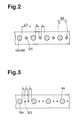
- the carcass cords 10 in the sheet include main cords 10M and auxiliary cords 10S which alternate in the longitudinal direction of the sheet.
- the main cords 10M and auxiliary cords 10S in the carcass ply 6A alternate in the circumferential direction of the tire.
- Fig.2 shows an example in which one auxiliary cord 10S is disposed between the main cords 10M.
- Fig.3 shows an example in which two auxiliary cords 10S are disposed between the main cords 10M.
- the main cords 10M are for providing support to the tire inner pressure and tire load. In other words, the main function of the main cords 10M is to reinforce the carcass ply. on the other hand.
- the auxiliary cords 10S are for controlling the outflow of the topping rubber 12 during vulcanization.
- a high-strength, high-modulus cord is used as the main cords 10M and the cord count of the main cords 10M is decreased.
- a strength index is the product Tm X Km of the cord strength Tm (N) of the main cord 10M and the cord count Km of the main cords 10M per 5 cm ply width
- the strength index is set in a range of from 4,000 to 20,000 N/5 cm in case of passenger car tires, and in case of heavy duty tires for trucks and buses, the strength index is set in a range of from 15,000 to 100,000 N/5 cm.
- the cord strength Tm is not less than 140 (N) in case of a passenger car tire, and in case of heavy duty tire for trucks and buses, the cord strength Tm is not less than 800 (N).
- the cord strength Tm may be increased by increasing the cord thickness Dm and/or using a material superior in the rupture strength. Therefore, it becomes possible to minimize the strength of the auxiliary cord as far as the auxiliary cords can prevent the outflow of the topping rubber.
- the auxiliary cords may have a less strength and/or less thickness than the main cords.
- the strength can be increased by 1) increasing the cord thickness Dm, 2) using high-strength, high-modulus organic fiber material such as high-modulus polyethylene, high-modulus vinylon, aromatic polyamide, polyolefin ketone and the like, or steel fiber material, and/or 3) changing the cord structure.
- the strength can be increased by 1) increasing the cord thickness Dm and/or 2) changing the cord construction.
- the cord thickness Ds is set in a range of from 0.1 to 0.67 times, more preferably 0.1 to 0.4 times the cord thickness Dm of the main cords 10M. If the thickness Ds is more than 0.67 times the thickness Dm, the tire weight increases contrary to the purpose of the present invention. If the thickness Ds is less than 0.1 times the thickness Dm, it becomes difficult to control the outflow of the topping rubber.
- the cord count of the carcass cords 10 is determined such that the gaps L therebetween are within a range of from 0.02 to 0.80 mm and substantially constant. If the gaps L are more than 0.80 mm, the outflow is liable to occur. If the gaps L are less than 0.02 mm, fretting wear is liable to be caused between the adjacent cords and separation from the toping rubber tends to occur.
- the above-mentioned inner liner 9 is made of air-impermeable rubber and extends over the tire inner surface facing the tire cavity with a substantially constant thickness.
- the air-impermeable rubber used is a butyl rubber compound including not less than 20 weight % of butyl rubber and/or halogenated butyl rubber as its base rubber material.
- a diene rubber can be used as the remaining part of the base rubber material, if any.
- a halogenide of isobutylene-paramethyl styrene copolymer can be also used instead of the butyl rubber and/or halogenated butyl rubber.
- the air-impermeable rubber is used as the topping rubber 12 for the carcass ply 6A and the inner liner rubber 9 is omitted.
- the air-impermeable rubber is used only in an inside part of the topping rubber facing the tire cavity, and in the outside part, a different rubber compound, e.g. diene rubber and the like is used.
- the above-mentioned belt includes a breaker 7 and optional band disposed radially outside the breaker 7.
- the breaker 7 comprises at least two cross plies 7A and 7B of cords laid parallel with each other at an angle of from 10 to 35 degrees with respect to the tire equator.
- steel cords and high performance organic fiber cords such as aromatic polyamide and the like can be suitably used.
- the belt 7 is composed of two cross breaker plies ply 7A and 7B.
- the breaker 7 composed of three or four plies is usually used.
- the test tires were disassembled, and the thickness of the carcass topping rubber covering the carcass cords was measured as the thickness t after the tire vulcanization and the thickness (t) is shown in Table 1 together with the thickness (t') before vulcanization.
Landscapes
- Engineering & Computer Science (AREA)
- Mechanical Engineering (AREA)
- Tires In General (AREA)
- Tyre Moulding (AREA)
Abstract
Description
The
Fig.2 shows an example in which one
Fig.3 shows an example in which two
the strength index is set in a range of from 4,000 to 20,000 N/5 cm in case of passenger car tires, and
in case of heavy duty tires for trucks and buses, the strength index is set in a range of from 15,000 to 100,000 N/5 cm.
It is preferable that the cord strength Tm is not less than 140 (N) in case of a passenger car tire, and in case of heavy duty tire for trucks and buses, the cord strength Tm is not less than 800 (N).
Incidentally, the cord strength Tm may be increased by increasing the cord thickness Dm and/or using a material superior in the rupture strength.
Therefore, it becomes possible to minimize the strength of the auxiliary cord as far as the auxiliary cords can prevent the outflow of the topping rubber. Thus, the auxiliary cords may have a less strength and/or less thickness than the main cords. For example, in case of the passenger car tires in which organic fiber material, e.g. nylon, polyester, rayon and the like is conventionally used in the carcass cords, the strength can be increased by 1) increasing the cord thickness Dm, 2) using high-strength, high-modulus organic fiber material such as high-modulus polyethylene, high-modulus vinylon, aromatic polyamide, polyolefin ketone and the like, or steel fiber material, and/or 3) changing the cord structure.
In case of the heavy duty tires in which steel cords are conventionally used as the carcass cords, the strength can be increased by 1) increasing the cord thickness Dm and/or 2) changing the cord construction.
Incidentally, the cord strength Ts of the
If the gaps L are more than 0.80 mm, the outflow is liable to occur. If the gaps L are less than 0.02 mm, fretting wear is liable to be caused between the adjacent cords and separation from the toping rubber tends to occur.
As the air-impermeable rubber, used is a butyl rubber compound including not less than 20 weight % of butyl rubber and/or halogenated butyl rubber as its base rubber material. A diene rubber can be used as the remaining part of the base rubber material, if any. In the air-impermeable rubber compound, a halogenide of isobutylene-paramethyl styrene copolymer can be also used instead of the butyl rubber and/or halogenated butyl rubber.
| Tire | Ref.A | Ex.A | Ref.B | Ex.B |
| Tire size | 195/65R14 | 195/65R14 | 11R22.5 | 11R22.5 |
| Carcass ply | Fig.5 | Fig.2 | Fig.5 | Fig.3 |
| Main cord | 1100dtex//2/2 | 1100dtex//2/2 | 3+8+13X0.175 | 3+8+13X0.175 |
| Material | HM polyester | HM polyester | steel | steel |
| Strength Tm (N) | 280 | 280 | 1510 | 1510 |
| Thickness Dm (mm) | 0.78 | 0.78 | 1.05 | 1.05 |
| Count Km /5cm | 45 | 45 | 26 | 26 |
| Tm X Km (N) | 12600 | 12600 | 39260 | 39260 |
| Auxiliary cord | -- | 490dtex | -- | 1X3X0.175 |
| Material | -- | 6-nylon | -- | steel |
| Strength Ts (N) | -- | 29 | -- | 189 |
| Thickness Ds (mm) | -- | 0.3 | -- | 0.37 |
| Number Ks | -- | 1 | -- | 2 |
| (Ts X Ks)/Tm | -- | 0.1 | -- | 0.25 |
| Gap L (mm) | 0.7 | 0.02 | 0.87 | 0.24 |
| Ds/Dm | -- | 0.38 | -- | 0.35 |
| Undulation Thickness | C | A | D | B |
| t (after) (mm) | 0.17 | 0.23 | 0.4 | 0.65 |
| t' (before) (mm) | 0.26 | 0.26 | 0.85 | 0.85 |
Claims (9)
- A pneumatic tire comprisinga tread portion,a pair of sidewall portions,a pair of bead portions,a carcass ply of cords extending between the bead portions through the tread portion and sidewall portions,the carcass cords including main cords for reinforcing purpose and auxiliary cords for controlling outflow of topping rubber during tire vulcanization,the main cords and auxiliary cords arranged alternately in the tire circumferential direction, andthe number of auxiliary cord(s) between the main cords being in a range of from one to three.
- A pneumatic tire according to claim 1, wherein
the auxiliary cords have a thickness DS less than the thickness Dm of the main cords. - A pneumatic tire according to claim 1 or 2, wherein
the auxiliary cords have a thickness DS in a range of from 0.1 to 0.67 times the thickness Dm of the main cords. - A pneumatic tire according to claim 1, 2 or 3, wherein
the gaps L between the carcass cords are in a range of from 0.02 to 0.80 mm. - A pneumatic tire according to claim 1, wherein
the main cords are an organic cord having a thickness Dm, and
the auxiliary cords are an organic cord having a thickness Ds less than the thickness Dm. - A pneumatic tire according to claim 1, wherein
the main cords are a polyester cord having a thickness Dm, and
the auxiliary cords are a nylon cord having a thickness Ds less than the thickness Dm. - A pneumatic tire according to claim 1, wherein
the main cords are a steel cord having a thickness Dm, and
the auxiliary cords are a steel cord having a thickness Ds less than the thickness Dm. - A pneumatic tire according to claim 1, wherein
the main cords are a steel cord, and
the auxiliary cords are an organic cord. - A pneumatic tire according to claim 1, wherein
an air-impermeable rubber compound is used as a topping rubber for the carcass ply.
Applications Claiming Priority (2)
| Application Number | Priority Date | Filing Date | Title |
|---|---|---|---|
| JP2001209664 | 2001-07-10 | ||
| JP2001209664A JP4188580B2 (en) | 2001-07-10 | 2001-07-10 | Pneumatic radial tire |
Publications (3)
| Publication Number | Publication Date |
|---|---|
| EP1275526A2 true EP1275526A2 (en) | 2003-01-15 |
| EP1275526A3 EP1275526A3 (en) | 2003-05-14 |
| EP1275526B1 EP1275526B1 (en) | 2007-05-23 |
Family
ID=19045288
Family Applications (1)
| Application Number | Title | Priority Date | Filing Date |
|---|---|---|---|
| EP02015107A Expired - Lifetime EP1275526B1 (en) | 2001-07-10 | 2002-07-05 | Pneumatic tire |
Country Status (4)
| Country | Link |
|---|---|
| US (1) | US6935395B2 (en) |
| EP (1) | EP1275526B1 (en) |
| JP (1) | JP4188580B2 (en) |
| DE (1) | DE60220215T2 (en) |
Cited By (3)
| Publication number | Priority date | Publication date | Assignee | Title |
|---|---|---|---|---|
| EP1498287A1 (en) * | 2003-07-18 | 2005-01-19 | Continental Aktiengesellschaft | Pneumatic tyre for vehicle wheels |
| WO2018070951A1 (en) * | 2016-10-13 | 2018-04-19 | Kordsa Teknik Tekstil Anonim Sirketi | Cap ply strip with alternate nylon 6,6 and pet cords |
| EP4212359A1 (en) * | 2022-01-14 | 2023-07-19 | Continental Reifen Deutschland GmbH | Pneumatic tyre for vehicles |
Families Citing this family (11)
| Publication number | Priority date | Publication date | Assignee | Title |
|---|---|---|---|---|
| JP4952263B2 (en) * | 2007-01-15 | 2012-06-13 | 横浜ゴム株式会社 | Pneumatic tire |
| JP2009227229A (en) * | 2008-03-25 | 2009-10-08 | Toyo Tire & Rubber Co Ltd | Pneumatic radial tire |
| FR2954219A1 (en) * | 2009-11-17 | 2011-06-24 | Michelin Soc Tech | PNEUMATIC COMPRISING CARCASS FRAME CABLES WITH DIFFERENT PERMEABILITIES |
| DE102012100513A1 (en) | 2012-01-23 | 2013-07-25 | Continental Reifen Deutschland Gmbh | Pneumatic tire for use in e.g. passenger car, has inner body bearing embedded in inner and radial outer rubber compounds that are gas-impermeably and freely formed of butyl and/or halobutyl rubber and directed towards interior part of tire |
| JP5349630B2 (en) * | 2012-02-06 | 2013-11-20 | 住友ゴム工業株式会社 | Pneumatic tire |
| JP5443554B2 (en) | 2012-08-01 | 2014-03-19 | 住友ゴム工業株式会社 | Pneumatic tire with inner liner |
| DE102015210838A1 (en) | 2015-06-12 | 2016-12-15 | Continental Reifen Deutschland Gmbh | Vehicle tires |
| EP3377336A4 (en) * | 2015-11-19 | 2019-06-19 | Bridgestone Americas Tire Operations, LLC | FIBER REINFORCING TABLE COMPRISING A FERROUS ELEMENT FOR MAGNETIC HANDLING |
| US20220048327A1 (en) * | 2018-12-13 | 2022-02-17 | Bridgestone Corporation | Tire |
| JP7353902B2 (en) * | 2019-10-04 | 2023-10-02 | 株式会社ブリヂストン | pneumatic tires |
| JP7815927B2 (en) * | 2022-03-30 | 2026-02-18 | 住友ゴム工業株式会社 | tire |
Family Cites Families (10)
| Publication number | Priority date | Publication date | Assignee | Title |
|---|---|---|---|---|
| US2986191A (en) * | 1957-07-01 | 1961-05-30 | Continental Gummi Werke Ag Fa | Tire |
| FR1310491A (en) * | 1961-03-15 | 1962-11-30 | Kleber Colombes | Improvements to tire casings |
| NL130258C (en) * | 1965-07-28 | |||
| FR2134244B1 (en) * | 1971-04-28 | 1973-12-28 | Michelin & Cie | |
| DE2851526A1 (en) * | 1978-11-29 | 1980-06-12 | Olbo Textilwerke Gmbh | Flexible reinforced elastomer - in which cable-twisted threads are finished for stiffness and bondability and embedded in elastomer matrix |
| US4363346A (en) * | 1981-09-23 | 1982-12-14 | The Goodyear Tire & Rubber Company | Pneumatic tire including gas absorbing cords |
| JPS60229806A (en) * | 1984-04-27 | 1985-11-15 | Yokohama Rubber Co Ltd:The | Pneumatic tire |
| EP0555071B1 (en) * | 1992-02-04 | 1996-11-13 | Bridgestone Corporation | Pneumatic radial tires |
| JPH06115308A (en) * | 1992-10-05 | 1994-04-26 | Bridgestone Corp | Pneumatic radial tire for heavy load |
| JP2962658B2 (en) * | 1994-08-22 | 1999-10-12 | 住友ゴム工業株式会社 | Pneumatic tubeless tire |
-
2001
- 2001-07-10 JP JP2001209664A patent/JP4188580B2/en not_active Expired - Lifetime
-
2002
- 2002-07-05 EP EP02015107A patent/EP1275526B1/en not_active Expired - Lifetime
- 2002-07-05 DE DE60220215T patent/DE60220215T2/en not_active Expired - Lifetime
- 2002-07-09 US US10/190,731 patent/US6935395B2/en not_active Expired - Fee Related
Cited By (4)
| Publication number | Priority date | Publication date | Assignee | Title |
|---|---|---|---|---|
| EP1498287A1 (en) * | 2003-07-18 | 2005-01-19 | Continental Aktiengesellschaft | Pneumatic tyre for vehicle wheels |
| WO2018070951A1 (en) * | 2016-10-13 | 2018-04-19 | Kordsa Teknik Tekstil Anonim Sirketi | Cap ply strip with alternate nylon 6,6 and pet cords |
| US10328749B2 (en) | 2016-10-13 | 2019-06-25 | Kordsa Teknik Tekstil Anonim Sirketi | Cap ply strip with alternate nylon 6,6 and PET cords |
| EP4212359A1 (en) * | 2022-01-14 | 2023-07-19 | Continental Reifen Deutschland GmbH | Pneumatic tyre for vehicles |
Also Published As
| Publication number | Publication date |
|---|---|
| EP1275526B1 (en) | 2007-05-23 |
| JP4188580B2 (en) | 2008-11-26 |
| DE60220215D1 (en) | 2007-07-05 |
| US20030024623A1 (en) | 2003-02-06 |
| JP2003025808A (en) | 2003-01-29 |
| EP1275526A3 (en) | 2003-05-14 |
| US6935395B2 (en) | 2005-08-30 |
| DE60220215T2 (en) | 2008-01-24 |
Similar Documents
| Publication | Publication Date | Title |
|---|---|---|
| EP1867497B1 (en) | Run-flat tire | |
| EP1201414B2 (en) | Method of manufacturing the sidewall of a pneumatic tire | |
| US6935395B2 (en) | Pneumatic tire with carcass ply including main cords and auxiliary cords | |
| US6510883B2 (en) | Pneumatic vehicle tire including rubber reinforcing plies in side wall regions | |
| EP1095797B1 (en) | Pneumatic tire | |
| EP0844110B1 (en) | Pneumatic tyre | |
| US20020014295A1 (en) | Run-flat tire | |
| US6273162B1 (en) | Pneumatic tire with specified bead portion | |
| US5280817A (en) | Radial pneumatic tire having contoured zones in the sidewalls | |
| EP0931676B1 (en) | Improvements to tyres | |
| EP0346106A1 (en) | Pneumatic tyre | |
| EP0744305B1 (en) | Pneumatic tire | |
| EP4371785B1 (en) | Aircraft radial tire | |
| EP0844109B1 (en) | Heavy duty radial tyre | |
| KR20010080337A (en) | Tire and method of making same | |
| EP0941873B1 (en) | Heavy duty pneumatic radial tires | |
| EP0677375A2 (en) | Method of building green radial tyres having low-section profile | |
| GB2198996A (en) | Radial tyres | |
| EP0810105B1 (en) | Pneumatic radial tires provided with a side portion reinforcing layer | |
| EP0990539B1 (en) | Tire with tread compound applied directly on the radially outermost reinforcement layer of belt reinforcement textile cords | |
| EP3922485B1 (en) | Tire for kart | |
| US6615889B1 (en) | Heavy duty radial tire | |
| US5238039A (en) | Pneumatic radial tires having carcass line with plural inflection points | |
| US7249622B2 (en) | Tire with deep tread grooves | |
| US20020112798A1 (en) | Radial ply tire having a sidewall reinforcement |
Legal Events
| Date | Code | Title | Description |
|---|---|---|---|
| PUAI | Public reference made under article 153(3) epc to a published international application that has entered the european phase |
Free format text: ORIGINAL CODE: 0009012 |
|
| AK | Designated contracting states |
Kind code of ref document: A2 Designated state(s): AT BE BG CH CY CZ DE DK EE ES FI FR GB GR IE IT LI LU MC NL PT SE SK TR |
|
| AX | Request for extension of the european patent |
Free format text: AL;LT;LV;MK;RO;SI |
|
| PUAL | Search report despatched |
Free format text: ORIGINAL CODE: 0009013 |
|
| AK | Designated contracting states |
Designated state(s): AT BE BG CH CY CZ DE DK EE ES FI FR GB GR IE IT LI LU MC NL PT SE SK TR |
|
| AX | Request for extension of the european patent |
Extension state: AL LT LV MK RO SI |
|
| 17P | Request for examination filed |
Effective date: 20031016 |
|
| AKX | Designation fees paid |
Designated state(s): DE FR GB |
|
| 17Q | First examination report despatched |
Effective date: 20040203 |
|
| GRAP | Despatch of communication of intention to grant a patent |
Free format text: ORIGINAL CODE: EPIDOSNIGR1 |
|
| GRAS | Grant fee paid |
Free format text: ORIGINAL CODE: EPIDOSNIGR3 |
|
| GRAA | (expected) grant |
Free format text: ORIGINAL CODE: 0009210 |
|
| AK | Designated contracting states |
Kind code of ref document: B1 Designated state(s): DE FR GB |
|
| REG | Reference to a national code |
Ref country code: GB Ref legal event code: FG4D |
|
| REF | Corresponds to: |
Ref document number: 60220215 Country of ref document: DE Date of ref document: 20070705 Kind code of ref document: P |
|
| ET | Fr: translation filed | ||
| PLBE | No opposition filed within time limit |
Free format text: ORIGINAL CODE: 0009261 |
|
| STAA | Information on the status of an ep patent application or granted ep patent |
Free format text: STATUS: NO OPPOSITION FILED WITHIN TIME LIMIT |
|
| 26N | No opposition filed |
Effective date: 20080226 |
|
| PGFP | Annual fee paid to national office [announced via postgrant information from national office to epo] |
Ref country code: GB Payment date: 20110629 Year of fee payment: 10 |
|
| PGFP | Annual fee paid to national office [announced via postgrant information from national office to epo] |
Ref country code: FR Payment date: 20110727 Year of fee payment: 10 |
|
| PGFP | Annual fee paid to national office [announced via postgrant information from national office to epo] |
Ref country code: DE Payment date: 20110629 Year of fee payment: 10 |
|
| GBPC | Gb: european patent ceased through non-payment of renewal fee |
Effective date: 20120705 |
|
| REG | Reference to a national code |
Ref country code: FR Ref legal event code: ST Effective date: 20130329 |
|
| PG25 | Lapsed in a contracting state [announced via postgrant information from national office to epo] |
Ref country code: FR Free format text: LAPSE BECAUSE OF NON-PAYMENT OF DUE FEES Effective date: 20120731 Ref country code: DE Free format text: LAPSE BECAUSE OF NON-PAYMENT OF DUE FEES Effective date: 20130201 Ref country code: GB Free format text: LAPSE BECAUSE OF NON-PAYMENT OF DUE FEES Effective date: 20120705 |
|
| REG | Reference to a national code |
Ref country code: DE Ref legal event code: R119 Ref document number: 60220215 Country of ref document: DE Effective date: 20130201 |