EP1275471A2 - Polishing fixture and method for fiber optic connectors - Google Patents
Polishing fixture and method for fiber optic connectors Download PDFInfo
- Publication number
- EP1275471A2 EP1275471A2 EP02015243A EP02015243A EP1275471A2 EP 1275471 A2 EP1275471 A2 EP 1275471A2 EP 02015243 A EP02015243 A EP 02015243A EP 02015243 A EP02015243 A EP 02015243A EP 1275471 A2 EP1275471 A2 EP 1275471A2
- Authority
- EP
- European Patent Office
- Prior art keywords
- fiber optic
- connector
- polishing
- spring
- optic connector
- Prior art date
- Legal status (The legal status is an assumption and is not a legal conclusion. Google has not performed a legal analysis and makes no representation as to the accuracy of the status listed.)
- Withdrawn
Links
Images




Classifications
-
- B—PERFORMING OPERATIONS; TRANSPORTING
- B24—GRINDING; POLISHING
- B24B—MACHINES, DEVICES, OR PROCESSES FOR GRINDING OR POLISHING; DRESSING OR CONDITIONING OF ABRADING SURFACES; FEEDING OF GRINDING, POLISHING, OR LAPPING AGENTS
- B24B19/00—Single-purpose machines or devices for particular grinding operations not covered by any other main group
- B24B19/22—Single-purpose machines or devices for particular grinding operations not covered by any other main group characterised by a special design with respect to properties of the material of non-metallic articles to be ground
- B24B19/226—Single-purpose machines or devices for particular grinding operations not covered by any other main group characterised by a special design with respect to properties of the material of non-metallic articles to be ground of the ends of optical fibres
Definitions
- This invention relates to a polishing fixture for use with a polishing machine to secure fiber optic connectors to the fixture for high precision polishing operations. More specifically, this invention relates to a novel fixture for securing springless fiber optic connectors thereto for polishing operations.
- Fiber optic connectors are an important link in a fiber optic transmission system. Fiber optic connectors provide a mechanical link between two terminal ends of optical fibers thereby permitting transmission through the system. It is important that the connecting terminal ends of the optical fibers are polished to a high precision to minimize the attenuation of signal across the mechanical link.
- connection typically have an integrated spring contained within the connector body.
- the term "connector” includes numerous fiber optic connectors which may have a variety of ferrule configurations, including, for example, springless fiber optic connectors such as a simplified plug-and-jack SC and ST connector and MTRJ connectors.
- springless fiber optic connectors such as a simplified plug-and-jack SC and ST connector and MTRJ connectors.
- the terminal ends of the optical fibers which protrude through the holes formed in the ferrule, extend through the bottom of the polishing fixtures and are polished by a polishing machine.
- the springless conventional polishing fixture secures the connectors in a fixed position and relies on the connector's integrated spring to compensate for the variation in the protrusion of the ferrules and optical fibers during polishing.
- Another object of the invention is to provide a polishing fixture that can compensate for the variation in the protrusion of optical fibers in springless fiber optic connectors.
- Another object of the invention is to provide a spring load to the fiber optic connector during polishing.
- a polishing fixture comprising a base plate having at least one puck assembly disposed thereon.
- the puck assembly comprises a connector receptacle attached to the base plate wherein the connector receptacle is adapted to receive a fiber optic connector for polishing.
- the puck assembly also includes a spring to bias the fiber optic connector during polishing.
- the connector receptacle is fixedly attached to the base plate. In another embodiment, the connector receptacle is movably attached to the base plate.
- the fiber optic connector is substantially fixed to the connector receptacle during polishing, and both the connector and the receptacle are biased toward the base plate of the polishing fixture.
- the fiber optic connector may be affixed to the connector receptacle during polishing by any known means, including, for example, a bayonet mount or snap fitting spring arms.
- the connector receptacle may be received in a spring housing, which may be directly affixed to the base plate.
- the biasing spring may be disposed on the outside or the inside of the connector receptacle.
- the fiber optic connector is movable relative to the connector receptacle.
- the spring preferably exerts a biasing force to bias the connector receptacle towards the base plate.
- the connector receptacle is directly affixed to the base plate.
- the spring may form a component of a spring plate assembly to exert the biasing force.
- the spring may be a cantilever or leaf spring positioned above the fiber optic connector to exert the biasing force.
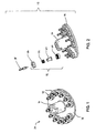
- polishing fixture 10 designates an embodiment of the polishing fixture in accordance with this invention.
- Polishing fixture 10 is adapted to have a number of plug-and-jack puck assemblies 12 fixedly mounted thereon. Although twelve puck assemblies 12 are illustrated in FIGS. 1 and 2, any number of puck assemblies 12 can be mounted on the polishing fixture 10.
- Polishing fixture 10 comprises a substantially circular base plate 14 and a hollow arm or central boss 16. As more specifically shown in FIGS. 3-5, each plug-and-jack puck assembly 12 is adapted to releasably receive a fiber optic connector 18.
- springless connectors 18 are shown in the accompanying drawings, the polishing fixtures 10 described herein are also suitable for use with connectors having an integrated spring.
- Puck assembly 12 comprises a spring housing 20, which is preferably fixedly attached to base plate 14 of polishing fixture 10, connector receptacle 22, compression spring 24, and retainer housing 26.
- Connector receptacle 22 has a tubular body 28 with bayonet slots 30 defined thereon and shoulder 32.
- Spring housing 20 is sized and dimensioned to receive connector receptacle 22.
- spring housing 20 comprises substantially flat, internal surfaces 34, which are adapted to match with corresponding flat surfaces 36 of shoulder 32 of connector receptacle 22. Substantially flat surfaces 34 and 36 cooperate to minimize rotational movement of the connectors 18 during polishing.
- Connector 18 preferably has two bayonet lugs 38 disposed thereon. Lugs 38 are sized and dimensioned to be lockably received in bayonet slots 30 of connector receptacle 22, such that there is no or minimal relative motion between connector 18 and connector receptacle 22. As particularly shown in FIG. 4, after the connector 18 is inserted through connector receptacle 22, terminal portion 40 of connector 18 is further inserted through well 42 of the spring housing 20 and extends therethrough, such that a portion of terminal portion 40 protrudes through the bottom of spring housing 20 and base 14 and is exposed for polishing. Terminal portion 40 defines a channel 44 that contains the terminal end of the optical fiber 46 for polishing.
- Compression spring 24 is disposed in the annular space between tubular body 28 of connector receptacle 22 and is partially compressed between shoulder 32 of connector receptacle 22 and a top portion of retainer housing 26.
- Retainer housing 26 is coupled to the spring housing 20 by matching threads shown most clearly in FIGS. 4 and 5.
- a portion of the connector receptacle 22 including bayonet slots 30 extends through the hole on top of retainer housing 26 to readily receive connector 18.
- terminal portion 40 of connector 18, with optical fiber 46 disposed therethrough protrudes through the bottom of the spring housing 20 and extends below the bottom of the base plate 14 of the polishing fixture 10.
- the polishing fixture is mounted to a rotary polishing machine.
- arm or boss 16 is mounted to an axle or spindle of the polishing machine and is fixedly connected to the machine, for example, by a swing-arm on the machine.
- Other types of attachments for the polishing machine such as, for example, the polishing apparatus shown in U.S. Patent No. 5,720,653, are also suitable for use with this invention.
- the protruded portion of the connector 18 with the optical fiber 46 rest on an electrically driven platen that extends up from the base of the polishing machine, and a downward force is applied to displace the connector 18 with the optical fiber 46 upward. This upward displacement causes the spring 24 to compress.
- this displacement applies a spring load of about two pounds, simulating a desirable spring force exerted by an integrated spring of a conventional connector.
- the protruded portions of the connectors 18 and optical fiber 46 are then effectively polished when the platen is driven by the polishing machine.
- the platen is driven by the polishing machine in a circular pattern.
- the platen is driven by the polishing machine in a non-circular pattern.
- the platen pushes the over-extended portion upward in the direction of arrow 48 in FIG. 4 against the force of spring 24.
- the protruded portions of all connectors 18 mounted on the polishing fixture are substantially at the same height before polishing begins, and polishing is carried out uniformly over all the mounted connectors 18.
- the polishing fixture of this invention is suitable for use with conventional connectors with integrated springs. In this situation, either spring 24 in puck assembly 12 or an integrated spring inside the conventional connector or both may be compressed.
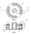
- FIGS. 6-9 illustrate another embodiment of the polishing assembly in accordance with this invention.
- Polishing fixture 50 is shown with a number of plug-and-jack puck assemblies 52 coupled thereto. Three puck assemblies 52 are shown wherein exploded views in various stages.
- a significant feature of this embodiment is that connector 18 is movable relative to the connector receptacle 54.
- connector receptacle 54 is fixedly connected directly to the base plate 14.
- connector receptacle 54 has a tubular body 56 defining a pair of vertical slots 58 adapted to receive bayonet lugs 38 on connector 18. Slots 58 allow the bayonet lugs 38 and connector 18 to be movable in the vertical direction within the slots.
- a spring plate assembly 60 is positioned above the connector 18 to exert a spring force on connector 18 during polishing and to compensate for the variation in the protrusion of the connector and optical fiber.
- Spring plate assembly 60 includes plate 62, a plurality of compression springs 64, a corresponding number of bolts 66, and an enclosing cap 68. As best shown in FIG. 7, bolts 66 are inserted through the top of cap 68 through pre-drilled holes and are then inserted through the corresponding springs 64 and are threaded through the threaded holes on plate 62. Due to the smooth upper portions of bolts 66, plate 62 is movable in the direction of arrow 70, shown in FIG. 9, against the force of springs 64.
- Connector 18 is inserted into body 56 of connector receptacle 54 such that lugs 38 are movably received in vertical slots 58 and terminal portion 40 extends through the bottom channel on the connector receptacle 54 and protrudes below base plate 14, as described above.
- Spring plate assembly 60 is then coupled with connector receptacle 54 by means of the corresponding threads, as shown. Thereafter, connector 18 abuts plate 62 and spring plate assembly 60 exerts a force on connector 18.
- Plate 62 and bolts 66 are movable in the direction of arrow 70 to exert a spring force on connector 18 and to compensate for the variation of the protrusion by connector 18 through base plate 14.
- FIGS. 10 and 11 show another embodiment in accordance with this invention. Similar to polishing fixture 50, polishing fixture 72 has base plate 14 and a plurality of connector receptacles 54 with vertical slots 58. Connectors 18 are inserted into connector receptacles 54 such that the connectors and the connector receptacles are movable relative to each other. Thereafter, clip ring 74 is placed over central boss 100, such that each cantilever arm 76 is positioned above each connector 18. Nut 78 is threaded over boss 100 to press clip ring 74 downward such that each cantilever arm 76 acts like a leaf spring to exert a spring force on each connector 18. Connectors 18 are also movable upward against the spring force of arms 76 to compensate for the variation in the protrusion of ferrules 18 with optical fibers 46.
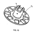
- FIGS. 12-15 represent another embodiment in accordance to this invention.
- Puck assembly 80 is sized and dimensioned to accept a non-circular connector 82.
- connector 82 is illustrated as a square-profiled connector.
- Non-circular connector 82 many have any polygonal, elliptical, or other profile.
- connector 82 and the connector receptacle are fixedly attached to each other, i . e ., they are not movable relative to each other, during polishing.
- puck assembly 80 comprises base 84, connector receptacle 86, compression spring 88, and nut 90.
- Base 84 which performs the same function as the spring housing 20 of polishing fixture 10, is fixedly attached to base plate 92, shown in FIG. 15.
- Connector receptacle 86 defines a hole through its bottom surface and is adapted to fit over boss 94 of base 84.
- Spring 88 is positioned over boss 94 and nut 90 is fixedly fitted, for example by press fitting, to the top of boss 94 to contain spring 88 between nut 90 and connector receptacle 86 as best shown in FIG. 14.
- Connector receptacle 86 is sized and configured to be movable in the direction of arrow 96 relative to base 84, against the force of spring 88.
- Adapter has cavity 96 adapted to receive connector 82, such that the connector is fixed to the adapter and both of these components are movable relative to base 84.
- Connector 82 has two spring prongs 98, which snap into cavity 96 to secure connector 82 to connector receptacle 86.
- the movement of connector 82 and connector receptacle 86 against the force of spring 88 and relative to base 84 exerts a spring force on the connector during polishing and compensates for the variation of the protrusion of the connectors 82 below the base plate 92.
Landscapes
- Engineering & Computer Science (AREA)
- Mechanical Engineering (AREA)
- Light Guides In General And Applications Therefor (AREA)
- Mechanical Coupling Of Light Guides (AREA)
- Grinding And Polishing Of Tertiary Curved Surfaces And Surfaces With Complex Shapes (AREA)
Abstract
Description
Hence, there remains a need in the art for a polishing fixture that can compensate for the variation in the protrusion of the ferrules and optical fibers in springless fiber optic connectors.
In accordance with one aspect of the invention, the fiber optic connector is substantially fixed to the connector receptacle during polishing, and both the connector and the receptacle are biased toward the base plate of the polishing fixture. The fiber optic connector may be affixed to the connector receptacle during polishing by any known means, including, for example, a bayonet mount or snap fitting spring arms. The connector receptacle may be received in a spring housing, which may be directly affixed to the base plate. Furthermore, the biasing spring may be disposed on the outside or the inside of the connector receptacle.
Claims (22)
- A polishing fixture comprising:a base plate for securing a puck assembly thereto;the puck assembly configured to engage a fiber optic connector, the puck assembly comprises:a connector receptacle for receiving the fiber optic connector for polishing, wherein the connector receptacle is attached to the base plate; anda spring for providing a biasing force to the fiber optic connector during polishing.
- The polishing fixture of claim 1, wherein the puck assembly further comprises:means for substantially eliminating the relative motion between the connector receptacle and the fiber optic connector.
- The polishing fixture of claim 2, wherein the means for substantially eliminating the relative motion between the connector receptacle and the fiber optic connector comprises:at least one bayonet lug, wherein the bayonet lug is sized and dimensioned to be lockably received in a bayonet slot on the connector receptacle.
- The polishing fixture of claim 1, wherein the fiber optic connector engages the connector receptacle using a bayonet connection.
- The polishing fixture of claim 1, wherein the fiber optic connector engages the connector receptacle using one or more snap fitting spring arms.
- The polishing fixture of claim 1, wherein the spring biases the connector receptacle towards the base plate.
- The polishing fixture of claim 1, wherein the puck assembly further comprises:a spring housing to secure the spring, wherein the spring housing is fixedly attached to the base plate.
- The polishing fixture of claim 1, wherein the spring is disposed around the connector receptacle.
- The polishing fixture of claim 1, wherein the spring is disposed inside the connector receptacle.
- The polishing fixture of claim 7, wherein the connector receptacle and the spring housing each comprise substantially corresponding straight edges to substantially eliminate relative rotational movement of the fiber optic connector during polishing.
- The polishing fixture of claim 1, wherein the connector receptacle is movable relative to the fiber optic connector.
- The polishing fixture of claim 11, wherein the polishing fixture further comprises:a spring plate assembly for use with the spring to exert the biasing force on the fiber optic connector during polishing and to compensate for the variation in the protrusion of the fiber optic connector and an optical fiber.
- The polishing fixture of claim 12, wherein the spring plate assembly comprises a plate, a plurality of compression springs, a plurality of bolts corresponding to an equal number of the compression springs, and an enclosing cap.
- The polishing fixture of claim 13, wherein the plate is biased by the spring to exert the biasing force.
- The polishing fixture of claim 12, wherein the polishing fixture further comprises:a clip ring having at least one cantilever arm for use with the spring plate assembly, wherein the cantilever arm exerts a spring force on the fiber optic connector.
- The polishing fixture of claim 15, wherein the fiber optic connector is positioned between the cantilever arm and the connector receptacle.
- A polishing fixture comprising:a base plate for securing a puck assembly thereto;the puck assembly configured to engage a fiber optic connector, the puck assembly comprises:a connector receptacle for receiving the fiber optic connector for polishing; anda spring for providing a biasing force to the fiber optic connector during polishing.
- A puck assembly attachable to a polishing fixture, the puck assembly comprises:a connector receptacle adapted to receive a fiber optic connector to polish; anda spring to bias the fiber optic connector during polishing..
- The puck assembly of claim 18, wherein the puck assembly further comprises:means for substantially eliminating the relative motion between the connector receptacle and the fiber optic connector.
- The puck assembly of claim 19, wherein the means for substantially eliminating the relative motion between the connector receptacle and the fiber optic connector comprises:at least one bayonet lug, wherein the bayonet lug is sized and dimensioned to be lockably received in a bayonet slot on the connector receptacle.
- The puck assembly of claim 20, wherein the connector receptacle is movable relative to the fiber optic connector.
- A method of using a polishing fixture to compensate for the variation in the protrusion of one or more springless fiber optic connectors, comprising:providing a puck assembly puck configured to engage the fiber optic connector;securing the puck assembly to a base plate;engaging the springless fiber optic connector in the puck assembly, wherein the puck assembly comprises:a connector receptacle for receiving the fiber optic connector for polishing, wherein the connector receptacle is attached to the base plate; anda spring for providing a biasing force to the fiber optic connector during polishing.applying a downward force to the polishing fixture to displace the springless fiber optic connector; andpolishing the terminal end of the fiber optic connector.
Applications Claiming Priority (2)
| Application Number | Priority Date | Filing Date | Title |
|---|---|---|---|
| US09/905,801 US20030027497A1 (en) | 2001-07-13 | 2001-07-13 | Polishing fixture and method for fiber optic connectors |
| US905801 | 2001-07-13 |
Publications (2)
| Publication Number | Publication Date |
|---|---|
| EP1275471A2 true EP1275471A2 (en) | 2003-01-15 |
| EP1275471A3 EP1275471A3 (en) | 2004-01-14 |
Family
ID=25421498
Family Applications (1)
| Application Number | Title | Priority Date | Filing Date |
|---|---|---|---|
| EP02015243A Withdrawn EP1275471A3 (en) | 2001-07-13 | 2002-07-09 | Polishing fixture and method for fiber optic connectors |
Country Status (3)
| Country | Link |
|---|---|
| US (1) | US20030027497A1 (en) |
| EP (1) | EP1275471A3 (en) |
| JP (1) | JP2003127055A (en) |
Cited By (3)
| Publication number | Priority date | Publication date | Assignee | Title |
|---|---|---|---|---|
| CN102848307A (en) * | 2012-09-13 | 2013-01-02 | 黄石晨信光电有限责任公司 | Special jig fixture for grinding non-standard optical fiber connectors |
| CN103481185A (en) * | 2013-09-22 | 2014-01-01 | 广西安捷讯电子科技有限公司 | Optical switch collimator grinding clamp |
| US8771039B2 (en) | 2011-05-25 | 2014-07-08 | Avago Technologies General Ip (Singapore) Pte. Ltd. | Optical fiber polishing jig for use with optical connectors of differing sizes and types |
Families Citing this family (5)
| Publication number | Priority date | Publication date | Assignee | Title |
|---|---|---|---|---|
| JP4223008B2 (en) | 2005-01-18 | 2009-02-12 | 株式会社精工技研 | Polishing jig for ferrule end polishing machine with optical fiber |
| KR101873914B1 (en) * | 2012-04-27 | 2018-07-06 | 코닝 리서치 앤드 디벨롭먼트 코포레이션 | Optical fiber connector polishing apparatus and method |
| CN104297863B (en) * | 2014-05-30 | 2016-03-23 | 中航光电科技股份有限公司 | Circular fiber optic connector |
| JP6263291B1 (en) * | 2017-02-20 | 2018-01-17 | 株式会社精工技研 | Polishing holder mounting jig and optical fiber ferrule polishing holder |
| EP3948377A4 (en) * | 2019-03-29 | 2023-02-22 | CommScope Technologies LLC | Fiber optic connector fabrication carrier |
Family Cites Families (4)
| Publication number | Priority date | Publication date | Assignee | Title |
|---|---|---|---|---|
| US4819386A (en) * | 1987-07-20 | 1989-04-11 | Northwestern Bell Corporation | Optic fiber sanding fixture and method of using |
| US5018316A (en) * | 1990-06-21 | 1991-05-28 | Amp Incorporated | Polishing fixture for optical fiber of push-pull connector |
| US5201148A (en) * | 1992-03-27 | 1993-04-13 | Amp Incorporated | Polishing bushing for polishing an optical fiber in an optical fiber connector |
| WO1996014960A2 (en) * | 1994-11-10 | 1996-05-23 | The Whitaker Corporation | Universal polishing fixture for polishing optical fiber connectors |
-
2001
- 2001-07-13 US US09/905,801 patent/US20030027497A1/en not_active Abandoned
-
2002
- 2002-07-09 EP EP02015243A patent/EP1275471A3/en not_active Withdrawn
- 2002-07-15 JP JP2002205717A patent/JP2003127055A/en active Pending
Cited By (4)
| Publication number | Priority date | Publication date | Assignee | Title |
|---|---|---|---|---|
| US8771039B2 (en) | 2011-05-25 | 2014-07-08 | Avago Technologies General Ip (Singapore) Pte. Ltd. | Optical fiber polishing jig for use with optical connectors of differing sizes and types |
| CN102848307A (en) * | 2012-09-13 | 2013-01-02 | 黄石晨信光电有限责任公司 | Special jig fixture for grinding non-standard optical fiber connectors |
| CN102848307B (en) * | 2012-09-13 | 2014-09-17 | 黄石晨信光电有限责任公司 | Special jig fixture for grinding non-standard optical fiber connectors |
| CN103481185A (en) * | 2013-09-22 | 2014-01-01 | 广西安捷讯电子科技有限公司 | Optical switch collimator grinding clamp |
Also Published As
| Publication number | Publication date |
|---|---|
| EP1275471A3 (en) | 2004-01-14 |
| JP2003127055A (en) | 2003-05-08 |
| US20030027497A1 (en) | 2003-02-06 |
Similar Documents
| Publication | Publication Date | Title |
|---|---|---|
| US5887095A (en) | Optical receptacle and housing therefor | |
| AU685528B2 (en) | Actuation tool and cap for fiber optic connector | |
| JP5106926B2 (en) | Actuating tools for fiber optic connectors | |
| JP5180402B2 (en) | Reversible fiber optic connector | |
| US5018316A (en) | Polishing fixture for optical fiber of push-pull connector | |
| US6234685B1 (en) | Quick connect fiber optic connector having a deformable barrel | |
| EP0835470B1 (en) | Optical fibre connector for fibres with cleaved and beveled ends | |
| CN101504476B (en) | Protective cover for field-installable connector | |
| EP1091225A3 (en) | Optical fiber tunable connector adapter | |
| US20100166372A1 (en) | Expanded beam, single fiber, fiber optic connector | |
| US5674114A (en) | Universal polishing plate for polishing machine | |
| US20060229006A1 (en) | Ferrule holder assembly for optical-fiber-end-face grinding apparatus | |
| EP0579056A1 (en) | Optical fiber polishing apparatus | |
| JPH07248433A (en) | Optical fiber connector assembly | |
| WO1996014960A2 (en) | Universal polishing fixture for polishing optical fiber connectors | |
| AU692111B2 (en) | Fiber optic connector element | |
| EP0835471A1 (en) | Bare fiber connector | |
| MY108415A (en) | Push-pull optical fiber connector. | |
| EP0831348A3 (en) | Optical connector | |
| US20030027497A1 (en) | Polishing fixture and method for fiber optic connectors | |
| US5140779A (en) | Optical fiber polishing tool | |
| WO2008100771A1 (en) | Remote grip optical fiber connector | |
| US20040038558A1 (en) | Fiber optic cable assembly | |
| EP0128044A2 (en) | Fiber optic connector having dual supporting surfaces and method of terminating fiber optic transmission members | |
| JPH0442806Y2 (en) |
Legal Events
| Date | Code | Title | Description |
|---|---|---|---|
| PUAI | Public reference made under article 153(3) epc to a published international application that has entered the european phase |
Free format text: ORIGINAL CODE: 0009012 |
|
| AK | Designated contracting states |
Kind code of ref document: A2 Designated state(s): AT BE BG CH CY CZ DE DK EE ES FI FR GB GR IE IT LI LU MC NL PT SE SK TR |
|
| AX | Request for extension of the european patent |
Free format text: AL;LT;LV;MK;RO;SI |
|
| PUAL | Search report despatched |
Free format text: ORIGINAL CODE: 0009013 |
|
| AK | Designated contracting states |
Kind code of ref document: A3 Designated state(s): AT BE BG CH CY CZ DE DK EE ES FI FR GB GR IE IT LI LU MC NL PT SE SK TR |
|
| AX | Request for extension of the european patent |
Extension state: AL LT LV MK RO SI |
|
| AKX | Designation fees paid | ||
| REG | Reference to a national code |
Ref country code: DE Ref legal event code: 8566 |
|
| STAA | Information on the status of an ep patent application or granted ep patent |
Free format text: STATUS: THE APPLICATION IS DEEMED TO BE WITHDRAWN |
|
| 18D | Application deemed to be withdrawn |
Effective date: 20040715 |