EP1275116B1 - Method for producing a component including a zirconium alloy - Google Patents
Method for producing a component including a zirconium alloy Download PDFInfo
- Publication number
- EP1275116B1 EP1275116B1 EP01916011A EP01916011A EP1275116B1 EP 1275116 B1 EP1275116 B1 EP 1275116B1 EP 01916011 A EP01916011 A EP 01916011A EP 01916011 A EP01916011 A EP 01916011A EP 1275116 B1 EP1275116 B1 EP 1275116B1
- Authority
- EP
- European Patent Office
- Prior art keywords
- hydrogen
- zirconium
- oxide layer
- oxide
- metal
- Prior art date
- Legal status (The legal status is an assumption and is not a legal conclusion. Google has not performed a legal analysis and makes no representation as to the accuracy of the status listed.)
- Expired - Lifetime
Links
- 229910001093 Zr alloy Inorganic materials 0.000 title claims abstract description 26
- 238000004519 manufacturing process Methods 0.000 title claims abstract description 6
- 229910052739 hydrogen Inorganic materials 0.000 claims abstract description 84
- 239000001257 hydrogen Substances 0.000 claims abstract description 84
- UFHFLCQGNIYNRP-UHFFFAOYSA-N Hydrogen Chemical compound [H][H] UFHFLCQGNIYNRP-UHFFFAOYSA-N 0.000 claims abstract description 81
- 229910052751 metal Inorganic materials 0.000 claims abstract description 54
- 239000002184 metal Substances 0.000 claims abstract description 54
- BASFCYQUMIYNBI-UHFFFAOYSA-N platinum Substances [Pt] BASFCYQUMIYNBI-UHFFFAOYSA-N 0.000 claims abstract description 49
- QCWXUUIWCKQGHC-UHFFFAOYSA-N Zirconium Chemical compound [Zr] QCWXUUIWCKQGHC-UHFFFAOYSA-N 0.000 claims abstract description 25
- 229910052697 platinum Inorganic materials 0.000 claims abstract description 25
- 229910052726 zirconium Inorganic materials 0.000 claims abstract description 25
- 230000007797 corrosion Effects 0.000 claims abstract description 13
- 238000005260 corrosion Methods 0.000 claims abstract description 13
- 238000000034 method Methods 0.000 claims abstract description 13
- RVTZCBVAJQQJTK-UHFFFAOYSA-N oxygen(2-);zirconium(4+) Chemical compound [O-2].[O-2].[Zr+4] RVTZCBVAJQQJTK-UHFFFAOYSA-N 0.000 claims abstract description 11
- 229910001928 zirconium oxide Inorganic materials 0.000 claims abstract description 11
- -1 platinum metals Chemical class 0.000 claims abstract description 5
- 229910052727 yttrium Inorganic materials 0.000 claims abstract description 4
- VWQVUPCCIRVNHF-UHFFFAOYSA-N yttrium atom Chemical compound [Y] VWQVUPCCIRVNHF-UHFFFAOYSA-N 0.000 claims abstract description 4
- 229910052746 lanthanum Inorganic materials 0.000 claims abstract description 3
- FZLIPJUXYLNCLC-UHFFFAOYSA-N lanthanum atom Chemical compound [La] FZLIPJUXYLNCLC-UHFFFAOYSA-N 0.000 claims abstract description 3
- 229910045601 alloy Inorganic materials 0.000 claims description 8
- 239000000956 alloy Substances 0.000 claims description 8
- 150000002431 hydrogen Chemical class 0.000 claims description 7
- 230000001681 protective effect Effects 0.000 claims description 2
- 239000010410 layer Substances 0.000 abstract description 82
- 229910052760 oxygen Inorganic materials 0.000 abstract description 37
- QVGXLLKOCUKJST-UHFFFAOYSA-N atomic oxygen Chemical compound [O] QVGXLLKOCUKJST-UHFFFAOYSA-N 0.000 abstract description 36
- 239000001301 oxygen Substances 0.000 abstract description 36
- 239000011241 protective layer Substances 0.000 abstract description 2
- 238000010521 absorption reaction Methods 0.000 description 21
- 238000005253 cladding Methods 0.000 description 17
- 230000007547 defect Effects 0.000 description 13
- 239000011148 porous material Substances 0.000 description 12
- 229910000420 cerium oxide Inorganic materials 0.000 description 10
- BMMGVYCKOGBVEV-UHFFFAOYSA-N oxo(oxoceriooxy)cerium Chemical compound [Ce]=O.O=[Ce]=O BMMGVYCKOGBVEV-UHFFFAOYSA-N 0.000 description 10
- 229910052684 Cerium Inorganic materials 0.000 description 8
- KJTLSVCANCCWHF-UHFFFAOYSA-N Ruthenium Chemical compound [Ru] KJTLSVCANCCWHF-UHFFFAOYSA-N 0.000 description 8
- GWXLDORMOJMVQZ-UHFFFAOYSA-N cerium Chemical compound [Ce] GWXLDORMOJMVQZ-UHFFFAOYSA-N 0.000 description 8
- 239000000463 material Substances 0.000 description 8
- 229910052707 ruthenium Inorganic materials 0.000 description 8
- XLYOFNOQVPJJNP-UHFFFAOYSA-N water Substances O XLYOFNOQVPJJNP-UHFFFAOYSA-N 0.000 description 8
- 238000010586 diagram Methods 0.000 description 7
- 238000010494 dissociation reaction Methods 0.000 description 7
- 230000005593 dissociations Effects 0.000 description 7
- 239000003758 nuclear fuel Substances 0.000 description 6
- 239000000446 fuel Substances 0.000 description 5
- GKOZUEZYRPOHIO-UHFFFAOYSA-N iridium atom Chemical compound [Ir] GKOZUEZYRPOHIO-UHFFFAOYSA-N 0.000 description 5
- KDLHZDBZIXYQEI-UHFFFAOYSA-N palladium Substances [Pd] KDLHZDBZIXYQEI-UHFFFAOYSA-N 0.000 description 5
- 239000010948 rhodium Substances 0.000 description 5
- MHOVAHRLVXNVSD-UHFFFAOYSA-N rhodium atom Chemical compound [Rh] MHOVAHRLVXNVSD-UHFFFAOYSA-N 0.000 description 5
- 239000011248 coating agent Substances 0.000 description 4
- 238000000576 coating method Methods 0.000 description 4
- 238000001035 drying Methods 0.000 description 4
- 230000036571 hydration Effects 0.000 description 4
- 238000006703 hydration reaction Methods 0.000 description 4
- 239000007788 liquid Substances 0.000 description 4
- 150000002739 metals Chemical class 0.000 description 4
- 239000000203 mixture Substances 0.000 description 4
- 230000003647 oxidation Effects 0.000 description 4
- 238000007254 oxidation reaction Methods 0.000 description 4
- VYZAMTAEIAYCRO-UHFFFAOYSA-N Chromium Chemical compound [Cr] VYZAMTAEIAYCRO-UHFFFAOYSA-N 0.000 description 3
- 238000004458 analytical method Methods 0.000 description 3
- 230000015572 biosynthetic process Effects 0.000 description 3
- 239000000498 cooling water Substances 0.000 description 3
- 239000007789 gas Substances 0.000 description 3
- 229910052741 iridium Inorganic materials 0.000 description 3
- 229910052763 palladium Inorganic materials 0.000 description 3
- 229910052703 rhodium Inorganic materials 0.000 description 3
- 229910001925 ruthenium oxide Inorganic materials 0.000 description 3
- WOCIAKWEIIZHES-UHFFFAOYSA-N ruthenium(iv) oxide Chemical compound O=[Ru]=O WOCIAKWEIIZHES-UHFFFAOYSA-N 0.000 description 3
- XEEYBQQBJWHFJM-UHFFFAOYSA-N Iron Chemical compound [Fe] XEEYBQQBJWHFJM-UHFFFAOYSA-N 0.000 description 2
- PXHVJJICTQNCMI-UHFFFAOYSA-N Nickel Chemical compound [Ni] PXHVJJICTQNCMI-UHFFFAOYSA-N 0.000 description 2
- 238000005275 alloying Methods 0.000 description 2
- 229910052804 chromium Inorganic materials 0.000 description 2
- 239000011651 chromium Substances 0.000 description 2
- 239000000356 contaminant Substances 0.000 description 2
- 239000002826 coolant Substances 0.000 description 2
- 230000007423 decrease Effects 0.000 description 2
- 230000003247 decreasing effect Effects 0.000 description 2
- 238000007598 dipping method Methods 0.000 description 2
- 229910000457 iridium oxide Inorganic materials 0.000 description 2
- 229910052762 osmium Inorganic materials 0.000 description 2
- SYQBFIAQOQZEGI-UHFFFAOYSA-N osmium atom Chemical compound [Os] SYQBFIAQOQZEGI-UHFFFAOYSA-N 0.000 description 2
- 238000010422 painting Methods 0.000 description 2
- 229910003446 platinum oxide Inorganic materials 0.000 description 2
- 229910003450 rhodium oxide Inorganic materials 0.000 description 2
- 125000006850 spacer group Chemical group 0.000 description 2
- 239000000758 substrate Substances 0.000 description 2
- ATJFFYVFTNAWJD-UHFFFAOYSA-N Tin Chemical compound [Sn] ATJFFYVFTNAWJD-UHFFFAOYSA-N 0.000 description 1
- 238000000429 assembly Methods 0.000 description 1
- 230000000712 assembly Effects 0.000 description 1
- 238000009835 boiling Methods 0.000 description 1
- 238000006243 chemical reaction Methods 0.000 description 1
- 238000005336 cracking Methods 0.000 description 1
- 238000009792 diffusion process Methods 0.000 description 1
- 238000002474 experimental method Methods 0.000 description 1
- 238000005984 hydrogenation reaction Methods 0.000 description 1
- 229910052742 iron Inorganic materials 0.000 description 1
- 230000002045 lasting effect Effects 0.000 description 1
- 230000007246 mechanism Effects 0.000 description 1
- 229910052759 nickel Inorganic materials 0.000 description 1
- 238000005554 pickling Methods 0.000 description 1
- 230000005855 radiation Effects 0.000 description 1
- 230000002285 radioactive effect Effects 0.000 description 1
- 239000000126 substance Substances 0.000 description 1
- 238000004381 surface treatment Methods 0.000 description 1
- QSGNKXDSTRDWKA-UHFFFAOYSA-N zirconium dihydride Chemical compound [ZrH2] QSGNKXDSTRDWKA-UHFFFAOYSA-N 0.000 description 1
- 229910000568 zirconium hydride Inorganic materials 0.000 description 1
Images




Classifications
-
- G—PHYSICS
- G21—NUCLEAR PHYSICS; NUCLEAR ENGINEERING
- G21C—NUCLEAR REACTORS
- G21C3/00—Reactor fuel elements and their assemblies; Selection of substances for use as reactor fuel elements
- G21C3/02—Fuel elements
- G21C3/04—Constructional details
- G21C3/06—Casings; Jackets
- G21C3/07—Casings; Jackets characterised by their material, e.g. alloys
-
- C—CHEMISTRY; METALLURGY
- C22—METALLURGY; FERROUS OR NON-FERROUS ALLOYS; TREATMENT OF ALLOYS OR NON-FERROUS METALS
- C22C—ALLOYS
- C22C16/00—Alloys based on zirconium
-
- C—CHEMISTRY; METALLURGY
- C23—COATING METALLIC MATERIAL; COATING MATERIAL WITH METALLIC MATERIAL; CHEMICAL SURFACE TREATMENT; DIFFUSION TREATMENT OF METALLIC MATERIAL; COATING BY VACUUM EVAPORATION, BY SPUTTERING, BY ION IMPLANTATION OR BY CHEMICAL VAPOUR DEPOSITION, IN GENERAL; INHIBITING CORROSION OF METALLIC MATERIAL OR INCRUSTATION IN GENERAL
- C23C—COATING METALLIC MATERIAL; COATING MATERIAL WITH METALLIC MATERIAL; SURFACE TREATMENT OF METALLIC MATERIAL BY DIFFUSION INTO THE SURFACE, BY CHEMICAL CONVERSION OR SUBSTITUTION; COATING BY VACUUM EVAPORATION, BY SPUTTERING, BY ION IMPLANTATION OR BY CHEMICAL VAPOUR DEPOSITION, IN GENERAL
- C23C8/00—Solid state diffusion of only non-metal elements into metallic material surfaces; Chemical surface treatment of metallic material by reaction of the surface with a reactive gas, leaving reaction products of surface material in the coating, e.g. conversion coatings, passivation of metals
- C23C8/02—Pretreatment of the material to be coated
-
- C—CHEMISTRY; METALLURGY
- C23—COATING METALLIC MATERIAL; COATING MATERIAL WITH METALLIC MATERIAL; CHEMICAL SURFACE TREATMENT; DIFFUSION TREATMENT OF METALLIC MATERIAL; COATING BY VACUUM EVAPORATION, BY SPUTTERING, BY ION IMPLANTATION OR BY CHEMICAL VAPOUR DEPOSITION, IN GENERAL; INHIBITING CORROSION OF METALLIC MATERIAL OR INCRUSTATION IN GENERAL
- C23C—COATING METALLIC MATERIAL; COATING MATERIAL WITH METALLIC MATERIAL; SURFACE TREATMENT OF METALLIC MATERIAL BY DIFFUSION INTO THE SURFACE, BY CHEMICAL CONVERSION OR SUBSTITUTION; COATING BY VACUUM EVAPORATION, BY SPUTTERING, BY ION IMPLANTATION OR BY CHEMICAL VAPOUR DEPOSITION, IN GENERAL
- C23C8/00—Solid state diffusion of only non-metal elements into metallic material surfaces; Chemical surface treatment of metallic material by reaction of the surface with a reactive gas, leaving reaction products of surface material in the coating, e.g. conversion coatings, passivation of metals
- C23C8/06—Solid state diffusion of only non-metal elements into metallic material surfaces; Chemical surface treatment of metallic material by reaction of the surface with a reactive gas, leaving reaction products of surface material in the coating, e.g. conversion coatings, passivation of metals using gases
- C23C8/08—Solid state diffusion of only non-metal elements into metallic material surfaces; Chemical surface treatment of metallic material by reaction of the surface with a reactive gas, leaving reaction products of surface material in the coating, e.g. conversion coatings, passivation of metals using gases only one element being applied
- C23C8/10—Oxidising
-
- C—CHEMISTRY; METALLURGY
- C23—COATING METALLIC MATERIAL; COATING MATERIAL WITH METALLIC MATERIAL; CHEMICAL SURFACE TREATMENT; DIFFUSION TREATMENT OF METALLIC MATERIAL; COATING BY VACUUM EVAPORATION, BY SPUTTERING, BY ION IMPLANTATION OR BY CHEMICAL VAPOUR DEPOSITION, IN GENERAL; INHIBITING CORROSION OF METALLIC MATERIAL OR INCRUSTATION IN GENERAL
- C23C—COATING METALLIC MATERIAL; COATING MATERIAL WITH METALLIC MATERIAL; SURFACE TREATMENT OF METALLIC MATERIAL BY DIFFUSION INTO THE SURFACE, BY CHEMICAL CONVERSION OR SUBSTITUTION; COATING BY VACUUM EVAPORATION, BY SPUTTERING, BY ION IMPLANTATION OR BY CHEMICAL VAPOUR DEPOSITION, IN GENERAL
- C23C8/00—Solid state diffusion of only non-metal elements into metallic material surfaces; Chemical surface treatment of metallic material by reaction of the surface with a reactive gas, leaving reaction products of surface material in the coating, e.g. conversion coatings, passivation of metals
- C23C8/06—Solid state diffusion of only non-metal elements into metallic material surfaces; Chemical surface treatment of metallic material by reaction of the surface with a reactive gas, leaving reaction products of surface material in the coating, e.g. conversion coatings, passivation of metals using gases
- C23C8/34—Solid state diffusion of only non-metal elements into metallic material surfaces; Chemical surface treatment of metallic material by reaction of the surface with a reactive gas, leaving reaction products of surface material in the coating, e.g. conversion coatings, passivation of metals using gases more than one element being applied in more than one step
-
- C—CHEMISTRY; METALLURGY
- C23—COATING METALLIC MATERIAL; COATING MATERIAL WITH METALLIC MATERIAL; CHEMICAL SURFACE TREATMENT; DIFFUSION TREATMENT OF METALLIC MATERIAL; COATING BY VACUUM EVAPORATION, BY SPUTTERING, BY ION IMPLANTATION OR BY CHEMICAL VAPOUR DEPOSITION, IN GENERAL; INHIBITING CORROSION OF METALLIC MATERIAL OR INCRUSTATION IN GENERAL
- C23C—COATING METALLIC MATERIAL; COATING MATERIAL WITH METALLIC MATERIAL; SURFACE TREATMENT OF METALLIC MATERIAL BY DIFFUSION INTO THE SURFACE, BY CHEMICAL CONVERSION OR SUBSTITUTION; COATING BY VACUUM EVAPORATION, BY SPUTTERING, BY ION IMPLANTATION OR BY CHEMICAL VAPOUR DEPOSITION, IN GENERAL
- C23C8/00—Solid state diffusion of only non-metal elements into metallic material surfaces; Chemical surface treatment of metallic material by reaction of the surface with a reactive gas, leaving reaction products of surface material in the coating, e.g. conversion coatings, passivation of metals
- C23C8/80—After-treatment
-
- Y—GENERAL TAGGING OF NEW TECHNOLOGICAL DEVELOPMENTS; GENERAL TAGGING OF CROSS-SECTIONAL TECHNOLOGIES SPANNING OVER SEVERAL SECTIONS OF THE IPC; TECHNICAL SUBJECTS COVERED BY FORMER USPC CROSS-REFERENCE ART COLLECTIONS [XRACs] AND DIGESTS
- Y02—TECHNOLOGIES OR APPLICATIONS FOR MITIGATION OR ADAPTATION AGAINST CLIMATE CHANGE
- Y02E—REDUCTION OF GREENHOUSE GAS [GHG] EMISSIONS, RELATED TO ENERGY GENERATION, TRANSMISSION OR DISTRIBUTION
- Y02E30/00—Energy generation of nuclear origin
- Y02E30/30—Nuclear fission reactors
Definitions
- the present invention relates to a method for manufacturing a component comprising zirconium alloy and which has a surface on which a corrosion protective oxide layer is formed, which comprises zirconium oxide, wherein the component intended to be in an oxidising environment and said oxide layer has an outer surface towards said oxidising environment, and a nuclear facility as defined in the preamble of claim 1 (see US-5,475,723 ) GB 896, 569 discloses a Zr alloy comprising Pd for a nuclear reactor.
- the reactor core comprises a number of fuel assemblies, which comprise a top plate and a bottom plate with a number of elongated, parallely placed tubular elements extending between the top plate and the bottom plate and a number of spacers axially distributed along and connected to the elongated tubular elements.
- the fuel assembly also comprises a large number of elongated fuel rods which are kept in place by the spacers between the top plate and the bottom plate according to a specific pattern and on specific distances relative to each other and to the elongated tubular elements.
- Each fuel rod contains nuclear fuel enclosed in a cladding tube.
- Cladding tubes for nuclear fuel is an example of such components.
- An attack on a cladding tube for nuclear fuel means in the worst possible case that a damage extending through the entire thickness of the cladding tube occurs so that the radioactive nuclear fuel inside the cladding tube leaks out into the cooling water of the reactor. This may be caused by both primary and secondary defects on the cladding tube.
- a primary defect extending through the whole thickness of the cladding tube means that water, steam or a combination of these streams in through the defect so that an area between the fuel and the inner surface of the cladding tube is filled with the water, the steam or the combination of these.
- the presence of the water, the steam or the combination of these in this area means that the cladding tube is in danger of being damaged through attacks on the inside of the tube. This attack is often caused through hydration.
- Such a defect is called a secondary defect and can only occur after a primary defect already has occurred.
- Both primary defects and secondary defects extending through the entire thickness of the cladding tube means that the nuclear fuel inside the cladding tube, and thus radioactivity, leaks out into the cooling water of the reactor. Secondary defects may occur at relatively long distances from the primary defects and have also usually the shape of long cracks or transverse breaks meaning that they are a serious type of defect.
- Zirconium is often used in materials for cladding tubes, which enclose the nuclear fuel in reactors because of its low neutron absorption ability and its good corrosion resistance.
- the cladding material is alloyed for example with tin with about a percentage of weight and with smaller contents of iron, nickel and chrome. The total content of alloying materials can be about some percentages of weight.
- the cooling water reacts with the cladding tube and forms zirconium oxide, wherein hydrogen is released.
- Zirconium oxide is relatively corrosion resistant. In an oxidising environment this depends on the fact that the oxide layer formed can resist further attacks. How efficiently the oxide layer can resist further attacks is mostly governed by the oxygen and hydrogen transport in the oxide.
- Hydrogen can react with the cladding material and form zirconium hydride, which can lead to large cracks being formed in the cladding material. It should be noted, however, that small amounts of contaminants might exist in the alloy, wherein hydrogen is usually mentioned. A typical content of hydrogen is about 10 ppm by weight.
- Hydrogen embrittlement means that the metal cracks more easily during mechanical stress. Hydrogen embrittlement may happen if the metal is heated in a hydrogen rich environment or if hydrogen is formed at the metal surface, for example in connection with corrosion, pickling and electrochemical surface treatment.
- How efficiently the oxide layer can resist further attacks also depends on the presence of microscopic pores, cavities and cracks in the oxide layer.
- An oxide layer that only grows in the interface between the oxide layer and the surrounding gas/liquid by way of metal transport through the oxide layer tends to have a bad adherence to the metal substrate.
- an oxide layer growing only in the interface between the metal substrate and the oxide layer tends to crack in the interface towards the surrounding gas/liquid.
- a prerequisite for pores, cavities and cracks to be able to disappear during the growth of the oxide layer is that an oxide is formed at the surfaces adjacent to these pores, cavities and cracks which in turn assumes that oxygen, preferably in dissociated form, and metal are transported to said surfaces.
- the purpose with the present invention is a method for manufacturing a zirconium based alloy with such a composition that a sustainable balance between metal and oxygen transport is achieved in the oxide layer formed when the zirconium based alloy is present in an oxidising environment.
- dense and durable oxide layers are obtained which can efficiently resist further attacks.
- these properties shall be optimised in respect of an application where the alloy is subjected to elevated radiation of the type of fast neutrons in a corrosive environment, such as in the reactor core of a nuclear facility.
- the nuclear facility may comprise a boiling water reactor or a pressure water reactor.
- the present invention is based on a number of tests made to map out which factors determine the oxidisation and hydration kinetics in zirconium and zirconium alloys, preferably in temperatures about 300-500°C.
- said metal will contribute to make the oxide layer more dense by oxide growth in the surfaces of the oxide layer which are adjacent to pores, cavities and cracks, wherein these defects will be minimised. In this way a dense and durable oxide layer will be formed, which will increase the corrosion resistance of the component in oxidising environments.
- platinum metals is meant platinum, palladium, rhodium, iridium, osmium and ruthenium.
- Zircaloy-2 comprises about 10 ppm by weight of hydrogen.
- an oxide layer is formed on the surface being in contact with the environment.
- tests have been carried out on tubes of Zircaloy-2 which have been hydrogenated, i.e. been brought to assimilate hydrogen by means of diffusion, of different degrees by being hydrogenated for different times.
- the hydrogenation has been carried out in two steps, where in a first step the tube of Zircaloy-2 in question has been exposed to hydrogen gas in an oven at 400°C during a certain time and in a second step been placed in a vacuum oven in order to level out possible hydrogen gradients. In this way the tubes have been brought to contain a certain hydrogen content, at least in a layer closest to the surface of the tube being in contact with the inner atmosphere of the oven. In the following when tubes of Zircaloy-2 with hydrogen contents above 10 ppm by weight are mentioned it is assumed that they have been treated in this way.
- tubes of Zircaloy-2 are mentioned with a hydrogen content ⁇ 10 ppm by weight the tube in question have been degassed of hydrogen at 800°C for a certain time so that at least a layer closest to the surface being in contact with the environment comprises less than 10 ppm by weight hydrogen.
- the two-step oxidisation is an established method whose purpose is to give information of where oxide is growing in the oxide layer. It is performed so that a sample, in this case a tube of Zircaloy-2, first is oxidised in 16,16 O 2 /H 2 O 16 and thereafter in 18,18 O 2 /H 2 O 18 or vice versa. By thereafter determining how 16 O and 18 O varies with depth in the oxide layer information can be obtained on where oxide was formed at the latest. Three tests have been carried out on tubes of Zircaloy-2 with different hydrogen content.
- the horizontal axis indicates the depth in the oxide layer, wherein the interface between the oxide layer and the oxidising environment coincides with the origin and the vertical axis indicates the presence of the respective oxygen isotopes in the oxide layer.
- Fig la the results are reported for a tube of Zircaloy-2 with a hydrogen content of about 1 ppm by weight.
- the tube is oxidised in 16, 16 O 2 and in a second step the same tube is oxidised in 18, 18 O 2 .
- the oxide layer borders the tube is marked with a dotted line.
- the oxide transport in the oxide layer towards the tube is higher than the metal transport in the oxide layer towards the oxidising environment.
- Fig 1b the results are reported for a tube of Zircaloy-2 with a hydrogen content of about 15 ppm by weight.
- the tube is oxidised in H 2 18 O and in a second step the same tube is oxidised in H 2 16 O. Where the oxide layer borders the tube is marked with a dotted line.
- the difference between the presence of 16 O in close vicinity to the interface between the oxide layer and the oxidising environment and the presence of 16 O in close vicinity of the interface between the oxide layer and the tube is less than the corresponding difference in Fig la.
- Fig 1a it is the difference between the presence of 18 O that may be studied.
- the oxide growth in H 2 O for a tube of Zircaloy-2 with a hydrogen content of about 15 ppm by weight is larger in the vicinity to the interface between the oxide layer and the oxidising environment than on the corresponding place for a tube of Zircaloy-2 with a hydrogen content of about 1 weight ppm, which was oxidised in O 2 .
- the conclusion one can make of these two tests is that the metal transport has increased in direction towards the interface between the oxide layer and the oxidising environment with increasing hydrogen content.
- Fig 1c the results are reported for a tube of Zircaloy-2 with a hydrogen content of about 40 ppm by weight.
- the tube is oxidised in 16, 16 O and in a second step the same tube is oxidised in 18, 18 O. Where the oxide layer borders the tube is marked with a dotted line.
- the presence of 18 O in the vicinity to the interface between the tube and the oxide layer is essentially equal to the presence of 18 O in the vicinity of the interface between the oxide layer and the oxidising environment.
- the oxide growth on a component comprising a zirconium alloy and intended to be in a nuclear reactor where the cooling medium comprises water means that hydrogen gas is produced during the oxidisation, wherein hydrogen may be absorbed by the zirconium alloy, i.e. the hydrogen content in the component will increase during operation.
- hydrogen gas is produced during the oxidisation, wherein hydrogen may be absorbed by the zirconium alloy, i.e. the hydrogen content in the component will increase during operation.
- an upper limit of the content of hydrogen in the zirconium alloy in an introductory phase i.e. an upper content of hydrogen that deliberately was added to the component.
- the oxide layer of a component in this case a component comprising a zirconium based alloy, can effectively resist the corrosion attack when the component is in an oxidising environment if the zirconium based alloy has such a composition that a durable balance between metal and oxygen transport is obtained in the oxide layer. It is thus necessary that it exists partly an oxygen transport and partly a metal transport towards the surfaces of the oxide layer which are adjacent to pores, cavities and cracks in the oxide layer so that oxide can be formed at these surfaces and therewith decrease the size of said pores, cavities and cracks, wherein a denser oxide layer is formed.
- a prerequisite to obtain oxide growth in the vicinity of the interface between the oxide layer and the zirconium alloy is that oxygen is transported thereto through for example grain boundaries or channels in the oxide layer. If oxygen is transported in the form of O and/or O 2 in the oxide layer the O 2 -molecules first have to dissociate. To examine whether the O 2 -molecules dissociate, a mixture of 16, 16 O 2 and 18, 18 O 2 may be used during the oxidisation, wherein one can follow the kinetics of the formation of 16, 18 O 2 -molecule.
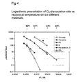
- Tests have been performed where the rate of formation of 16,18 O 2 have been measured when exposing different materials in 16, 16 O 2 and 18, 18 O 2 at 20 mbar, wherein the temperature has been varied.
- the test series is reported in Fig 4 .
- the horizontal axis indicates the reciprocal temperature in 1/K and the vertical axis indicates the logarithm of the dissociation rate of O 2 in ⁇ mol O/cm 2 ,hour.
- On the topside of Fig 4 the temperature in °C is given.
- a first sample comprising zirconium oxide
- a second sample comprising cerium oxide
- a third sample of platinum a fourth sample comprising rhodium
- a fifth sample comprising iridium and a sixth sample comprising ruthenium, and more precisely ruthenium oxide applied onto zirconium oxide.
- the oxygen molecules are dissociated at the interface to the surrounding atmosphere. As shown in Fig 4 the oxygen dissociation rate is high for zirconium or rather its oxide at temperatures > about 800°C. At temperatures ⁇ 500°C the oxygen dissociation rate is higher for cerium oxide, platinum, rhodium, iridium and ruthenium oxide than for zirconium oxide.
- the conclusion one can make from this test series is that at low temperatures ( ⁇ 500°C) an increased transport of dissociated oxygen is made possible by the presence of cerium oxide and in particular of platinum, rhodium, iridium and ruthenium oxide.
- Fig 5 the results are reported from a test series made on a sample of zirconium being exposed in 20 mbar O 2 at 450°C.
- the samples have been polished mechanically with SiC-paper to 1200 mesh.
- Three samples have been analysed, namely zirconium with a hydrogen content of about 50 ppm by weight, zirconium with a hydrogen content of about 50 ppm by weight coated with cerium oxide and zirconium with a hydrogen content of about 200 weight-ppm coated with cerium oxide.
- the coating can for example be applied by painting the sample with cerium oxide together with an indifferent carrier, after which a drying is carried out, preferably at an elevated temperature.
- the coating can be applied by dipping the sample in a liquid medium containing cerium oxide, after which drying is carried out, preferably at an elevated temperature.
- the horizontal axis indicates the oxidisation time and the vertical axis indicates the oxygen absorption in ⁇ molO/cm 2 .
- the oxygen absorption rate i.e. the oxidisation rate of the sample with 200 ppm by weight hydrogen with presence of cerium oxide is lower than the oxidisation rate of the sample with 50 ppm by weight of hydrogen both with and without the presence of cerium oxide.
- Fig 6 a test series is reported which has been performed in order to analyse the influence from hydrogen, cerium, platinum and ruthenium.
- the horizontal axis indicates the oxygen absorption in ⁇ molO/cm 2 and the vertical axis indicates the oxygen absorption rate in ⁇ molO/cm 2 ,hour.
- the starting-point of the test series was two samples of zirconium, which have been polished mechanically with a SiC-paper to 1200 mesh.
- the samples originally comprised hydrogen to a content of about 200 ppm by weight and was treated with cerium.
- the samples were exposed in 20 mbar O 2 at 450°C.
- about 100 ppm by weight of hydrogen has been added to the samples, wherein the samples thus comprised about 300 ppm by weight hydrogen.
- the sample was then exposed in 20 mbar O 2 at 450°C.
- the first sample has again been treated with cerium, wherein this sample after each respective step was exposed in 20 mbar O 2 at 450°C.
- this sample has been treated with platinum followed by exposure in 20 mbar O 2 at 450°C.
- the second sample which also comprised 300 ppm by weight of hydrogen was exposed in 20 mbar O 2 at 450°C to an oxide thickness of about 170 ⁇ molO/cm 2 , whereafter the sample was treated with ruthenium. Thereafter, the sample was again exposed in 20 mbar O 2 at 450°C.
- the best corrosion resistance i.e. the lowest oxidation rate, for the sample is obtained when it was treated with ruthenium.
- an about 2 mm wide area was coated with platinum interiourly in a Zircaloy tube having a length of 1 mm. Thereafter, the tube was exposed interiourly at 370°C in about 10 mbar water during 72 hours, whereafter an analysis of the absorption of hydrogen and oxygen was performed.
- an approximately 40% lower oxygen absorption and an approximately 80% lower hydrogen absorption than on a non-coated area was coated with platinum interiourly in a Zircaloy tube having a length of 1 mm.
- a part of a component 1 comprising an element 2, which can contain zirconium or a zirconium alloy.
- the element 2 has a surface 3 upon which a corrosion protective layer 4 is formed.
- the oxide layer 4 comprises zirconium oxide.
- the oxide layer 4 has an outer surface 5 facing an oxidising environment 6.
- pores 7 In the oxide layer 4 there are pores 7.
- cavities 8 Furthermore there are cavities 8 in the oxide layer 4 where the oxide layer borders the surface 3 and cracks 9 in the oxide layer 4 where the oxide layer faces the oxidising environment 6.
- the surprising discovery lies in the contribution of hydrogen and certain metals such as cerium, platinum and ruthenium to making the oxide layer formed on a component 1 of the type described in connection with Fig 7a more dense.
- at least one layer 10 of the element 2 has to comprise hydrogen and at least some metal, such as cerium or platinum.
- a component 1 of the type described in connection to Fig 7a it is possible to obtain a lasting balance between the metal and oxygen transport through the whole oxide layer 4.
- Fig 7a there is a surface 11 facing the pores 7, a surface 12 facing the cavity 8 and a surface 13 facing the crack 9.
- a durable balance between metal and oxide transport through the whole oxide layer 4 means that an oxide will be formed on the surfaces 11, 12 and 13, wherein the size of the pores, cavities, and cracks will be reduced, cf. Fig 7b .
- Cerium belongs to the metal group of lanthanum elements, wherein the layer 10 may contain any of the metals in said group.
- platinum belongs to the group of platinum metals, wherein the layer 10 may comprise any of the platinum metals, i.e. platinum, palladium, iridium, rhodium, osmium and ruthenium.
- oxygen is more easily dissociated with yttrium than with zirconium, wherein the layer 10 may comprise yttrium.
- Said metals may be applied on the component 1 by painting the component 1 with the metal together with an indifferent carrier, after which drying takes place, preferably at an elevated temperature.
- the coating may be applied by dipping the component 1 in a liquid medium containing the metal, after which drying takes place, preferably at an elevated temperature. It is also possible to add the metal in connection with manufacturing of the component 1 through mixture of the metal, zirconium and possible other alloying substances in a melted state, i.e. the metal is alloyed into the component. For the last mentioned method for addition of the metal the metal will exist homogeneously throughout the component.
Landscapes
- Chemical & Material Sciences (AREA)
- Engineering & Computer Science (AREA)
- Metallurgy (AREA)
- Mechanical Engineering (AREA)
- Organic Chemistry (AREA)
- Materials Engineering (AREA)
- Chemical Kinetics & Catalysis (AREA)
- Physics & Mathematics (AREA)
- General Engineering & Computer Science (AREA)
- High Energy & Nuclear Physics (AREA)
- Plasma & Fusion (AREA)
- Other Surface Treatments For Metallic Materials (AREA)
- Preventing Corrosion Or Incrustation Of Metals (AREA)
- Inorganic Compounds Of Heavy Metals (AREA)
- Catalysts (AREA)
- Solid-Sorbent Or Filter-Aiding Compositions (AREA)
- Organic Low-Molecular-Weight Compounds And Preparation Thereof (AREA)
Abstract
Description
- The present invention relates to a method for manufacturing a component comprising zirconium alloy and which has a surface on which a corrosion protective oxide layer is formed, which comprises zirconium oxide, wherein the component intended to be in an oxidising environment and said oxide layer has an outer surface towards said oxidising environment, and a nuclear facility as defined in the preamble of claim 1 (see
US-5,475,723 )GB 896, 569 - Components in nuclear facilities are often subjected to attacks caused by hydration and oxidisation hence it may be interesting to deposit a coating on the surface of the components to protect them. Cladding tubes for nuclear fuel is an example of such components. An attack on a cladding tube for nuclear fuel means in the worst possible case that a damage extending through the entire thickness of the cladding tube occurs so that the radioactive nuclear fuel inside the cladding tube leaks out into the cooling water of the reactor. This may be caused by both primary and secondary defects on the cladding tube.
- Primary defects occur from attacks on the outer surface of the cladding tube and are in particular caused by wear from foreign objects. A primary defect extending through the whole thickness of the cladding tube means that water, steam or a combination of these streams in through the defect so that an area between the fuel and the inner surface of the cladding tube is filled with the water, the steam or the combination of these. The presence of the water, the steam or the combination of these in this area means that the cladding tube is in danger of being damaged through attacks on the inside of the tube. This attack is often caused through hydration. Such a defect is called a secondary defect and can only occur after a primary defect already has occurred. Both primary defects and secondary defects extending through the entire thickness of the cladding tube means that the nuclear fuel inside the cladding tube, and thus radioactivity, leaks out into the cooling water of the reactor. Secondary defects may occur at relatively long distances from the primary defects and have also usually the shape of long cracks or transverse breaks meaning that they are a serious type of defect.
- Zirconium is often used in materials for cladding tubes, which enclose the nuclear fuel in reactors because of its low neutron absorption ability and its good corrosion resistance. In order to enhance the mechanical properties of the material and to increase its corrosion resistance the cladding material is alloyed for example with tin with about a percentage of weight and with smaller contents of iron, nickel and chrome. The total content of alloying materials can be about some percentages of weight. During operation the cooling water reacts with the cladding tube and forms zirconium oxide, wherein hydrogen is released. Zirconium oxide is relatively corrosion resistant. In an oxidising environment this depends on the fact that the oxide layer formed can resist further attacks. How efficiently the oxide layer can resist further attacks is mostly governed by the oxygen and hydrogen transport in the oxide. Hydrogen can react with the cladding material and form zirconium hydride, which can lead to large cracks being formed in the cladding material. It should be noted, however, that small amounts of contaminants might exist in the alloy, wherein hydrogen is usually mentioned. A typical content of hydrogen is about 10 ppm by weight.
- That hydrogen is regarded as a contaminant is based partly on the knowledge of embrittlement of a metal through absorption of large amounts of hydrogen, a so-called hydrogen embrittlement. Hydrogen embrittlement means that the metal cracks more easily during mechanical stress. Hydrogen embrittlement may happen if the metal is heated in a hydrogen rich environment or if hydrogen is formed at the metal surface, for example in connection with corrosion, pickling and electrochemical surface treatment.
- How efficiently the oxide layer can resist further attacks also depends on the presence of microscopic pores, cavities and cracks in the oxide layer. An oxide layer that only grows in the interface between the oxide layer and the surrounding gas/liquid by way of metal transport through the oxide layer tends to have a bad adherence to the metal substrate. Furthermore an oxide layer growing only in the interface between the metal substrate and the oxide layer tends to crack in the interface towards the surrounding gas/liquid. A prerequisite for pores, cavities and cracks to be able to disappear during the growth of the oxide layer is that an oxide is formed at the surfaces adjacent to these pores, cavities and cracks which in turn assumes that oxygen, preferably in dissociated form, and metal are transported to said surfaces.
- In "Oxidation of Metals, Vol. 51, Nos ¾, 1999; Hydrogen in Chromium: Influence on the high-temperature Oxidation Kinetics in O2, Oxide-Growth Mechanisms, and Scale Adherence; B Tveten et al." it has been reported that an increased hydrogen content in chromium leads to increased metal transport and increased oxide growth in the interface between the oxide layer and the surrounding gas phase. It is also reported in said article that the presence of hydrogen in the metal results in less adherence of the oxide layer to the metal through decreased oxidisation in the interface between the metal and the oxide layer. Thus the presence of hydrogen in metal contributes to a decreased corrosion resistance.
- The purpose with the present invention is a method for manufacturing a zirconium based alloy with such a composition that a sustainable balance between metal and oxygen transport is achieved in the oxide layer formed when the zirconium based alloy is present in an oxidising environment. In this way dense and durable oxide layers are obtained which can efficiently resist further attacks. In particular these properties shall be optimised in respect of an application
where the alloy is subjected to elevated radiation of the type of fast neutrons in a corrosive environment, such as in the reactor core of a nuclear facility. The nuclear facility may comprise a boiling water reactor or a pressure water reactor. - The present invention is based on a number of tests made to map out which factors determine the oxidisation and hydration kinetics in zirconium and zirconium alloys, preferably in temperatures about 300-500°C. During these tests the surprising discovery has been made that with the method mentioned in the introduction which has the characteristics defined in the characterising part of
claim 1, said metal will contribute to make the oxide layer more dense by oxide growth in the surfaces of the oxide layer which are adjacent to pores, cavities and cracks, wherein these defects will be minimised. In this way a dense and durable oxide layer will be formed, which will increase the corrosion resistance of the component in oxidising environments. By platinum metals is meant platinum, palladium, rhodium, iridium, osmium and ruthenium. - Further characteristics of the method are evident from the independent claims, i.e. claims 2 to 6.
- In the following description of performed tests the attached drawings will be referred to, in which
- Fig 1a-c
- shows three diagrams illustrating the oxygen occurrence as a function of the oxide depth for samples comprising a zirconium alloy with different hydrogen content,
- Fig 2
- shows a diagram illustrating the oxygen absorption rate as a function of hydrogen content for samples of a zirconium alloy exposed in 20 mbar O2 at 450°C,
- Fig 3
- shows a diagram illustrating the oxygen absorption rate as a function of hydrogen content for samples of a zirconium alloy exposed in 20 mbar H2O at 450°C,
- Fig 4
- shows a diagram illustrating the dissociation rate of O2 as a function of the reciprocal temperature for different materials exposed in 20 mbar O2,
- Fig 5
- shows a diagram illustrating the oxide growth for samples of zirconium with different hydrogen content which have been exposed in O2 at 450°C,
wherein two samples have been treated with cerium, - Fig 6
- shows a diagram illustrating the oxygen absorption rate as a function of the oxide layer thickness for samples, treated with hydrogen, cerium, platinum and ruthenium and exposed in O2 at 450°C, and
- Fig 7a
- shows how pores, cavities, and cracks may appear in an oxide layer formed on a component, and
- Fig 7b
- shows how the pores, cavities, and cracks in
Fig 7a have been reduced with the help of oxide growth. - Most tests have been carried out on tubes comprising a zirconium alloy called Zircaloy-2. Zircaloy-2 comprises about 10 ppm by weight of hydrogen. When components of zirconium alloys are present in an oxidising environment an oxide layer is formed on the surface being in contact with the environment. In order to map out how, for example, the hydrogen content in a zirconium alloy affects the metal transport in such an oxide layer tests have been carried out on tubes of Zircaloy-2 which have been hydrogenated, i.e. been brought to assimilate hydrogen by means of diffusion, of different degrees by being hydrogenated for different times. The hydrogenation has been carried out in two steps,
where in a first step the tube of Zircaloy-2 in question has been exposed to hydrogen gas in an oven at 400°C during a certain time and in a second step been placed in a vacuum oven in order to level out possible hydrogen gradients. In this way the tubes have been brought to contain a certain hydrogen content, at least in a layer closest to the surface of the tube being in contact with the inner atmosphere of the oven. In the following when tubes of Zircaloy-2 with hydrogen contents above 10 ppm by weight are mentioned it is assumed that they have been treated in this way. However, when in the following, tubes of Zircaloy-2 are mentioned with a hydrogen content <10 ppm by weight the tube in question have been degassed of hydrogen at 800°C for a certain time so that at least a layer closest to the surface being in contact with the environment comprises less than 10 ppm by weight hydrogen. - In order to examine how the hydrogen content of a zirconium alloy affects the metal transport in the zirconium oxide a two-step oxidisation was carried out in O2 and H2O respectively. The two-step oxidisation is an established method whose purpose is to give information of where oxide is growing in the oxide layer. It is performed so that a sample, in this case a tube of Zircaloy-2, first is oxidised in 16,16O2/H2O16 and thereafter in 18,18O2/H2O18 or vice versa. By thereafter determining how 16O and 18O varies with depth in the oxide layer information can be obtained on where oxide was formed at the latest. Three tests have been carried out on tubes of Zircaloy-2 with different hydrogen content. After the oxidisation tests the tubes have been coated with a thin layer of Au in order to avoid charging during the analysis. The horizontal axis indicates the depth in the oxide layer, wherein the interface between the oxide layer and the oxidising environment coincides with the origin and the vertical axis indicates the presence of the respective oxygen isotopes in the oxide layer.
- In Fig la the results are reported for a tube of Zircaloy-2 with a hydrogen content of about 1 ppm by weight. In a first step the tube is oxidised in 16, 16O2 and in a second step the same tube is oxidised in 18, 18O2. Where the oxide layer borders the tube is marked with a dotted line. As shown in Fig la 18O is present mainly close to the interface between the oxide layer and the tube, thus the conclusion is that the oxide transport in the oxide layer towards the tube is higher than the metal transport in the oxide layer towards the oxidising environment.
- In
Fig 1b the results are reported for a tube of Zircaloy-2 with a hydrogen content of about 15 ppm by weight. In a first step the tube is oxidised in H2 18O and in a second step the same tube is oxidised in H2 16O. Where the oxide layer borders the tube is marked with a dotted line. As shown inFig 1b the difference between the presence of 16O in close vicinity to the interface between the oxide layer and the oxidising environment and the presence of 16O in close vicinity of the interface between the oxide layer and the tube is less than the corresponding difference in Fig la. InFig 1a it is the difference between the presence of 18O that may be studied. Thus the oxide growth in H2O for a tube of Zircaloy-2 with a hydrogen content of about 15 ppm by weight is larger in the vicinity to the interface between the oxide layer and the oxidising environment than on the corresponding place for a tube of Zircaloy-2 with a hydrogen content of about 1 weight ppm, which was oxidised in O2. The conclusion one can make of these two tests is that the metal transport has increased in direction towards the interface between the oxide layer and the oxidising environment with increasing hydrogen content. - In
Fig 1c the results are reported for a tube of Zircaloy-2 with a hydrogen content of about 40 ppm by weight. In a first step the tube is oxidised in 16, 16O and in a second step the same tube is oxidised in 18, 18O. Where the oxide layer borders the tube is marked with a dotted line. As shown inFig 1c the presence of 18O in the vicinity to the interface between the tube and the oxide layer is essentially equal to the presence of 18O in the vicinity of the interface between the oxide layer and the oxidising environment. - The conclusion from the test series being reported in connection with
Fig 1a-c is that an increased hydrogen content in a zirconium alloy leads to an increased oxide growth in the interface between the oxide layer and the oxidising environment because of an increased metal transport in the oxide layer. - For a component comprising a zirconium alloy and being designed to be in a nuclear reactor one strives for a slow oxidisation rate. Tests have been carried out on tubes of Zircaloy-2 where the hydrogen content have varied from essentially 0 to a few hundred ppm by weight and where the tubes have been exposed in 20mbar O2 at 450°C. The result is illustrated in a diagram in
Fig 2 . The horizontal axis indicates the hydrogen content in ppm by weight and the vertical axis indicates the oxygen absorption rate in µmolO/cm2,hour. The oxide thickness has been between 20-30µm. The conclusion one can make from this test series is that the oxygen absorption rate, i.e. the oxidisation rate is larger for a tube of Zircaloy-2 without presence of hydrogen than for a tube of Zircaloy-2 with a hydrogen content of about 10 ppm by weight. - In order to have an oxide growth in vicinity of the contact surface between the oxide layer and the oxidising environment it is constructive if a zirconium alloy comprises hydrogen, compare with the reports of the tests in connection with
fig 1a-c . If however, the oxide growth primarily takes place in vicinity of the interface between the oxide layer and the oxidising environment the adherence of the oxide layer to the zirconium alloy may deteriorate and lead to cracking and in the worst case flaking, so called scaling, wherein the corrosion rate increases and therewith the consumption of metal increases. Furthermore the oxide growth on a component comprising a zirconium alloy and intended to be in a nuclear reactor where the cooling medium comprises water means that hydrogen gas is produced during the oxidisation, wherein hydrogen may be absorbed by the zirconium alloy, i.e. the hydrogen content in the component will increase during operation. Thus there is an upper limit of the content of hydrogen in the zirconium alloy in an introductory phase, i.e. an upper content of hydrogen that deliberately was added to the component. - In one test series tubes of Zircaloy-2 with different contents of hydrogen have been exposed in 20 mbar H2O at 450°C. The result of this test series is reported in
Fig 3 . The horizontal axis indicates the hydrogen content in ppm by weight and the vertical axis indicates the oxygen absorption rate in µmolO/cm2,hour. A conclusion one can make from this test series is that the oxygen absorption rate, i.e. the oxidisation rate, decreases with increased hydrogen content until a hydrogen content of about 200 ppm by weight, after which the oxidisation rate increases. Thus the hydrogen content in a component comprising a zirconium alloy should not in an introductory phase surpass 200 ppm by weight when oxidised in H2O, i.e. at the most 200 ppm by weight of hydrogen should deliberately be added to the component. - The oxide layer of a component, in this case a component comprising a zirconium based alloy, can effectively resist the corrosion attack when the component is in an oxidising environment if the zirconium based alloy has such a composition that a durable balance between metal and oxygen transport is obtained in the oxide layer. It is thus necessary that it exists partly an oxygen transport and partly a metal transport towards the surfaces of the oxide layer which are adjacent to pores, cavities and cracks in the oxide layer so that oxide can be formed at these surfaces and therewith decrease the size of said pores, cavities and cracks, wherein a denser oxide layer is formed. One can roughly separate three areas from where it is desirable with formation of oxide, namely in connection to cavities present in the oxide layer where the latter borders the component, in connection to pores in the oxide layer and in connection to the cracks present in the oxide layer where the oxide layer adjoins the oxidising environment, cf.
Fig 7a-b . As reported in connection toFig 1a-1c a better metal transport in the oxide layer is obtained if the zirconium alloy comprises hydrogen. However it has been shown in the tests performed that zirconium oxide does not dissociate oxygen sufficiently efficiently to obtain a sufficiently good balance between the transport of dissociated oxygen and the transport of metal in the oxide layer, wherein a dense and durable oxide layer which effectively can resist further attacks is not obtained. Above all this is true for temperatures <500°C. In a light water reactor in operation the temperature in the reactor is less than 500°C. The temperature in the reactor is rather around 300°C. - A prerequisite to obtain oxide growth in the vicinity of the interface between the oxide layer and the zirconium alloy is that oxygen is transported thereto through for example grain boundaries or channels in the oxide layer. If oxygen is transported in the form of O and/or O2 in the oxide layer the O2-molecules first have to dissociate. To examine whether the O2-molecules dissociate, a mixture of 16, 16O2 and 18, 18O2 may be used during the oxidisation, wherein one can follow the kinetics of the formation of 16, 18O2-molecule.
- Tests have been performed where the rate of formation of 16,18O2 have been measured when exposing different materials in 16, 16O2 and 18, 18O2 at 20 mbar, wherein the temperature has been varied. The test series is reported in
Fig 4 . The horizontal axis indicates the reciprocal temperature in 1/K and the vertical axis indicates the logarithm of the dissociation rate of O2 in µmol O/cm2,hour. On the topside ofFig 4 the temperature in °C is given. Six samples have been analysed, a first sample comprising zirconium oxide, a second sample comprising cerium oxide, a third sample of platinum, a fourth sample comprising rhodium, a fifth sample comprising iridium and a sixth sample comprising ruthenium, and more precisely ruthenium oxide applied onto zirconium oxide. The oxygen molecules are dissociated at the interface to the surrounding atmosphere. As shown inFig 4 the oxygen dissociation rate is high for zirconium or rather its oxide at temperatures > about 800°C. At temperatures < 500°C the oxygen dissociation rate is higher for cerium oxide, platinum, rhodium, iridium and ruthenium oxide than for zirconium oxide. The conclusion one can make from this test series is that at low temperatures (<500°C) an increased transport of dissociated oxygen is made possible by the presence of cerium oxide and in particular of platinum, rhodium, iridium and ruthenium oxide. - In
Fig 5 the results are reported from a test series made on a sample of zirconium being exposed in 20 mbar O2 at 450°C. The samples have been polished mechanically with SiC-paper to 1200 mesh. Three samples have been analysed, namely zirconium with a hydrogen content of about 50 ppm by weight, zirconium with a hydrogen content of about 50 ppm by weight coated with cerium oxide and zirconium with a hydrogen content of about 200 weight-ppm coated with cerium oxide. The coating can for example be applied by painting the sample with cerium oxide together with an indifferent carrier, after which a drying is carried out, preferably at an elevated temperature. Alternatively the coating can be applied by dipping the sample in a liquid medium containing cerium oxide, after which drying is carried out, preferably at an elevated temperature. The horizontal axis indicates the oxidisation time and the vertical axis indicates the oxygen absorption in µmolO/cm2. As shown inFig 5 the oxygen absorption rate, i.e. the oxidisation rate of the sample with 200 ppm by weight hydrogen with presence of cerium oxide is lower than the oxidisation rate of the sample with 50 ppm by weight of hydrogen both with and without the presence of cerium oxide. The conclusion one can make from this test series is that the best balance between the oxygen transport and the metal transport concerning the oxidation inFig 5 is obtained in the oxide layer of the sample with a hydrogen content of about 200 ppm by weight, which have been treated with cerium oxide. - In
Fig 6 a test series is reported which has been performed in order to analyse the influence from hydrogen, cerium, platinum and ruthenium. The horizontal axis indicates the oxygen absorption in µmolO/cm2 and the vertical axis indicates the oxygen absorption rate in µmolO/cm2,hour. The starting-point of the test series was two samples of zirconium, which have been polished mechanically with a SiC-paper to 1200 mesh. The samples originally comprised hydrogen to a content of about 200 ppm by weight and was treated with cerium. The samples were exposed in 20 mbar O2 at 450°C. In a second step about 100 ppm by weight of hydrogen has been added to the samples, wherein the samples thus comprised about 300 ppm by weight hydrogen. The sample was then exposed in 20 mbar O2 at 450°C. In a third and fourth step the first sample has again been treated with cerium, wherein this sample after each respective step was exposed in 20 mbar O2 at 450°C. In a fifth and last step this sample has been treated with platinum followed by exposure in 20 mbar O2 at 450°C. The second sample, which also comprised 300 ppm by weight of hydrogen was exposed in 20 mbar O2 at 450°C to an oxide thickness of about 170 µmolO/cm2, whereafter the sample was treated with ruthenium. Thereafter, the sample was again exposed in 20 mbar O2 at 450°C. As shown inFig 6 the best corrosion resistance i.e. the lowest oxidation rate, for the sample is obtained when it was treated with ruthenium. - Tests have shown that the oxide on a sample of zirconium which have been treated with platinum protects more effectively against both oxygen absorption and hydrogen absorption than the oxide on a sample of zirconium which has not been treated with platinum, i.e. for the platinum treated sample both the oxidisation rate and the hydration rate is lower than for the non- platinum treated sample. This despite the fact that the platinum treated sample contained more hydrogen from the beginning than the non-platinum treated sample. The platinum treated sample contained 300 ppm by weight hydrogen and the non-platinum treated sample contained 180 ppm by weight hydrogen, The results from the tests are reported in the table below. The dissociation rate of O2 is also reported in the table below,
where it is clear that the high dissociation rate can be coupled to the low oxygen absorption rate, which is consistent with earlier reported tests. - In the table below the reaction data for zirconium samples exposed in 20 mbar O2 and 20 mbar H2 respectively at 450°C are shown. The oxide thickness of the samples was about 15 µm.
Sample 1 contained 180 ppm by weight hydrogen andsample 2 contained 300 ppm by weight hydrogen. Furthermoresample 2 was treated with platinum.Oxygen dissociation rate µmolO/cm2,hour Oxygen absorption rate µmolO/cm2,hour Hydrogen absorption rate µmolH/cm2, hour Sample 1 <0,02 0,085 0,54 Sample 213 0,045 0,15 - In a further experiment, an about 2 mm wide area was coated with platinum interiourly in a Zircaloy tube having a length of 1 mm. Thereafter, the tube was exposed interiourly at 370°C in about 10 mbar water during 72 hours, whereafter an analysis of the absorption of hydrogen and oxygen was performed. On a platinum-coated area, an approximately 40% lower oxygen absorption and an approximately 80% lower hydrogen absorption than on a non-coated area.
- In
Fig 7a a part of acomponent 1 is shown comprising anelement 2, which can contain zirconium or a zirconium alloy. Theelement 2 has a surface 3 upon which a corrosion protective layer 4 is formed. The oxide layer 4 comprises zirconium oxide. The oxide layer 4 has anouter surface 5 facing an oxidisingenvironment 6. In the oxide layer 4 there arepores 7. Furthermore there arecavities 8 in the oxide layer 4 where the oxide layer borders the surface 3 andcracks 9 in the oxide layer 4 where the oxide layer faces the oxidisingenvironment 6. - As a basis for the present invention and as already mentioned the surprising discovery lies in the contribution of hydrogen and certain metals such as cerium, platinum and ruthenium to making the oxide layer formed on a
component 1 of the type described in connection withFig 7a more dense. Thus at least onelayer 10 of theelement 2 has to comprise hydrogen and at least some metal, such as cerium or platinum. - With a
component 1 of the type described in connection toFig 7a it is possible to obtain a lasting balance between the metal and oxygen transport through the whole oxide layer 4. As shown inFig 7a there is asurface 11 facing thepores 7, asurface 12 facing thecavity 8 and asurface 13 facing thecrack 9. A durable balance between metal and oxide transport through the whole oxide layer 4 means that an oxide will be formed on thesurfaces Fig 7b . - Cerium belongs to the metal group of lanthanum elements,
wherein thelayer 10 may contain any of the metals in said group. Furthermore platinum belongs to the group of platinum metals, wherein thelayer 10 may comprise any of the platinum metals, i.e. platinum, palladium, iridium, rhodium, osmium and ruthenium. Furthermore oxygen is more easily dissociated with yttrium than with zirconium, wherein thelayer 10 may comprise yttrium. Said metals may be applied on thecomponent 1 by painting thecomponent 1 with the metal together with an indifferent carrier, after which drying takes place, preferably at an elevated temperature. Alternatively the coating may be applied by dipping thecomponent 1 in a liquid medium containing the metal, after which drying takes place, preferably at an elevated temperature. It is also possible to add the metal in connection with manufacturing of thecomponent 1 through mixture of the metal, zirconium and possible other alloying substances in a melted state, i.e. the metal is alloyed into the component. For the last mentioned method for addition of the metal the metal will exist homogeneously throughout the component. - The present invention is not limited to the shown embodiment but can be varied and modified within the scope of the claims.
Claims (6)
- A method for manufacturing of a component (1) comprising an element (2), which consists of a zirconium based alloy and a layer (10), which element (2) has a surface (3) on which a corrosion protective oxide layer (4) is formed, which oxide layer (4) comprises zirconium oxide, wherein the layer (10) borders said surface (3) and thus said oxide layer (4), wherein the component (1) is intended to be in an oxidising environment (6) and said oxide layer (4) has an outer surface (5) towards said oxidising environment (6), wherein the layer (10) of the element (2) consists of
hydrogen, said hydrogen being arranged to promote a transport of zirconium inside the oxide layer (4) towards said outer surface (5),
at least a metal from the group of lanthanum elements and/or from the group of platinum metals and/or yttrium which in its elementary form or as an oxide has the ability to effectively dissociate O2 and H2O, and
optionally a zirconium based alloy,
characterised in that said hydrogen in said layer (10) is added by exposing the component (1) in hydrogen gas at an elevated temperature, wherein the layer (10) of the element (2) comprises initially at least 20 ppm by weight hydrogen and initially at the most 200 ppm by weight hydrogen. - A method according to claim 1, characterised in that the component (1) is exposed in hydrogen gas at said elevated temperature for as long a time that said hydrogen content is reached.
- A method according to any one of the claims 1 and 2,
characterised in that said temperature is about 400°C. - A method according to any one of the claims 1 to 3,
characterised in that said metal is added mainly to said layer (10) of the element (2) by applying the metal on the component (1). - A method according to claim 4, characterised in that said metal is applied on said outer surface (5).
- A method according to any one of the claims 1 to 5,
characterised in that said metal is added to the component by mixing the metal with said zirconium or zirconium alloy, wherein both the metal and said zirconium or said zirconium alloy is present in an essentially melted condition when they are mixed.
Applications Claiming Priority (3)
| Application Number | Priority Date | Filing Date | Title |
|---|---|---|---|
| SE0000919A SE516045C2 (en) | 2000-03-20 | 2000-03-20 | Component comprising a zirconium alloy, method of manufacturing said component, and a nuclear plant comprising said component |
| SE0000919 | 2000-03-20 | ||
| PCT/SE2001/000576 WO2001071728A1 (en) | 2000-03-20 | 2001-03-20 | A component including a zirconium alloy, a method for producing said component, and a nuclear plant including said component |
Publications (2)
| Publication Number | Publication Date |
|---|---|
| EP1275116A1 EP1275116A1 (en) | 2003-01-15 |
| EP1275116B1 true EP1275116B1 (en) | 2009-07-29 |
Family
ID=20278875
Family Applications (1)
| Application Number | Title | Priority Date | Filing Date |
|---|---|---|---|
| EP01916011A Expired - Lifetime EP1275116B1 (en) | 2000-03-20 | 2001-03-20 | Method for producing a component including a zirconium alloy |
Country Status (9)
| Country | Link |
|---|---|
| US (1) | US7232611B2 (en) |
| EP (1) | EP1275116B1 (en) |
| JP (1) | JP5243680B2 (en) |
| AT (1) | ATE438180T1 (en) |
| AU (1) | AU2001242954A1 (en) |
| DE (1) | DE60139388D1 (en) |
| ES (1) | ES2330614T3 (en) |
| SE (1) | SE516045C2 (en) |
| WO (1) | WO2001071728A1 (en) |
Families Citing this family (5)
| Publication number | Priority date | Publication date | Assignee | Title |
|---|---|---|---|---|
| SE524428C3 (en) | 2002-12-20 | 2004-09-08 | Westinghouse Atom Ab | Nuclear fuel rod and process for producing a nuclear fuel rod |
| US9165691B2 (en) * | 2009-04-17 | 2015-10-20 | Ge-Hitachi Nuclear Energy Americas Llc | Burnable poison materials and apparatuses for nuclear reactors and methods of using the same |
| JP5649056B2 (en) * | 2011-01-18 | 2015-01-07 | 一般財団法人電力中央研究所 | Corrosion-resistant member and manufacturing method thereof |
| US10217533B2 (en) | 2013-08-30 | 2019-02-26 | Electric Power Research Institute, Inc. | Fuel rod cladding and methods for making and using same |
| EP3488026A4 (en) * | 2016-07-22 | 2020-03-25 | Westinghouse Electric Company Llc | SPRAYING METHOD FOR COATING NUCLEAR FUELS TO ADD A CORROSION-RESISTANT BARRIER LAYER |
Family Cites Families (21)
| Publication number | Priority date | Publication date | Assignee | Title |
|---|---|---|---|---|
| DK125207B (en) * | 1970-08-21 | 1973-01-15 | Atomenergikommissionen | Process for the preparation of dispersion-enhanced zirconium products. |
| US4197145A (en) * | 1974-12-23 | 1980-04-08 | General Electric Company | Zirconium-base alloy structural component for nuclear reactor and method |
| US4483720A (en) * | 1981-11-27 | 1984-11-20 | S R I International | Process for applying thermal barrier coatings to metals |
| US5035957A (en) * | 1981-11-27 | 1991-07-30 | Sri International | Coated metal product and precursor for forming same |
| US4849082A (en) * | 1986-02-03 | 1989-07-18 | The Babcock & Wilcox Company | Ion implantation of zirconium alloys with hafnium |
| US5089455A (en) * | 1989-08-11 | 1992-02-18 | Corning Incorporated | Thin flexible sintered structures |
| US5814262A (en) * | 1989-08-11 | 1998-09-29 | Corning Incorporated | Method for producing thin flexible sintered structures |
| US5130080A (en) * | 1990-04-02 | 1992-07-14 | General Electric Company | Method of providing extended life expectancy for components of boiling water reactors |
| DE9206038U1 (en) * | 1992-02-28 | 1992-07-16 | Siemens AG, 80333 München | Material and structural part made of modified Zircaloy |
| WO1993018520A1 (en) * | 1992-03-13 | 1993-09-16 | Siemens Aktiengesellschaft | Nuclear reactor fuel rod with double layer cladding tube |
| US5475723A (en) * | 1994-03-21 | 1995-12-12 | General Electric Company | Nuclear fuel cladding with hydrogen absorbing inner liner |
| US5427866A (en) * | 1994-03-28 | 1995-06-27 | General Electric Company | Platinum, rhodium, or palladium protective coatings in thermal barrier coating systems |
| JPH07333370A (en) * | 1994-06-09 | 1995-12-22 | Toshiba Corp | Zircaloy fuel cladding tube and its corrosion inhibition method and apparatus |
| SE503349C2 (en) * | 1994-09-09 | 1996-05-28 | Asea Atom Ab | Nuclear fuel elements comprising a housing with an outer layer of Zr-Sn-Fe alloy |
| US6103386A (en) * | 1994-11-18 | 2000-08-15 | Allied Signal Inc | Thermal barrier coating with alumina bond inhibitor |
| US5793830A (en) * | 1995-07-03 | 1998-08-11 | General Electric Company | Metal alloy coating for mitigation of stress corrosion cracking of metal components in high-temperature water |
| JPH1048371A (en) * | 1996-08-06 | 1998-02-20 | Toshiba Corp | Nuclear power plant |
| GB9617267D0 (en) * | 1996-08-16 | 1996-09-25 | Rolls Royce Plc | A metallic article having a thermal barrier coating and a method of application thereof |
| FR2757181B1 (en) * | 1996-12-12 | 1999-02-12 | Snecma | PROCESS FOR PRODUCING A HIGH EFFICIENCY PROTECTIVE COATING AGAINST HIGH TEMPERATURE CORROSION FOR SUPERALLOYS, PROTECTIVE COATING OBTAINED BY THIS PROCESS AND PARTS PROTECTED BY THIS COATING |
| FR2768750B1 (en) * | 1997-09-25 | 1999-11-05 | Snecma | PROCESS FOR IMPROVING OXIDATION AND CORROSION RESISTANCE OF A SUPERALLOY PART AND SUPERALLOY PART OBTAINED BY THIS PROCESS |
| US6767418B1 (en) * | 1999-04-23 | 2004-07-27 | Terumo Kabushiki Kaisha | Ti-Zr type alloy and medical appliance formed thereof |
-
2000
- 2000-03-20 SE SE0000919A patent/SE516045C2/en not_active IP Right Cessation
-
2001
- 2001-03-20 US US10/204,846 patent/US7232611B2/en not_active Expired - Lifetime
- 2001-03-20 ES ES01916011T patent/ES2330614T3/en not_active Expired - Lifetime
- 2001-03-20 JP JP2001569825A patent/JP5243680B2/en not_active Expired - Fee Related
- 2001-03-20 AU AU2001242954A patent/AU2001242954A1/en not_active Abandoned
- 2001-03-20 WO PCT/SE2001/000576 patent/WO2001071728A1/en not_active Ceased
- 2001-03-20 AT AT01916011T patent/ATE438180T1/en not_active IP Right Cessation
- 2001-03-20 EP EP01916011A patent/EP1275116B1/en not_active Expired - Lifetime
- 2001-03-20 DE DE60139388T patent/DE60139388D1/en not_active Expired - Lifetime
Also Published As
| Publication number | Publication date |
|---|---|
| US7232611B2 (en) | 2007-06-19 |
| AU2001242954A1 (en) | 2001-10-03 |
| WO2001071728A1 (en) | 2001-09-27 |
| US20030079808A1 (en) | 2003-05-01 |
| JP2003528328A (en) | 2003-09-24 |
| ES2330614T3 (en) | 2009-12-14 |
| SE0000919D0 (en) | 2000-03-20 |
| ATE438180T1 (en) | 2009-08-15 |
| DE60139388D1 (en) | 2009-09-10 |
| SE516045C2 (en) | 2001-11-12 |
| SE0000919L (en) | 2001-09-21 |
| JP5243680B2 (en) | 2013-07-24 |
| EP1275116A1 (en) | 2003-01-15 |
Similar Documents
| Publication | Publication Date | Title |
|---|---|---|
| Pahl et al. | Irradiation behavior of metallic fast reactor fuels | |
| Steinbrück et al. | Oxidation of advanced zirconium cladding alloys in steam at temperatures in the range of 600–1200° C | |
| FI101814B (en) | Material and structural part of modified zircaloy | |
| Garde et al. | Corrosion behavior of Zircaloy-4 cladding with varying tin content in high-temperature pressurized water reactors | |
| US5366690A (en) | Zirconium alloy with tin, nitrogen, and niobium additions | |
| US5436947A (en) | Zirconium alloy fuel cladding | |
| EP0409405A2 (en) | Nuclear fuel element, and method of forming same | |
| EP0651396B1 (en) | Process for improving corrosion resistance of zirconium or zirconium alloy barrier cladding | |
| Ledergerber et al. | Characterization of high burnup fuel for safety related fuel testing | |
| GB2063915A (en) | Method for forming nuclear fuel containers of a composite construction and the product thereof | |
| US7232611B2 (en) | Component including a zirconium alloy, a method for producing said component, and a nuclear plant including said component | |
| Lan et al. | The challenge of acquiring a satisfactory EBSD result of CWSR Zircaloy‐4 cladding tube | |
| Billot | Experimental and Theoretical Studies of | |
| CA1209726A (en) | Zirconium alloy barrier having improved corrosion resistance | |
| Kass | Techniques and Precautions: Corrosion Testing of Two Zirconium Alloys | |
| Kass | Corrosion and hydrogen pickup of Zircaloy in concentrated lithium hydroxide solutions | |
| EP0986069B1 (en) | A device and a method for preventing shadow corrosion | |
| Klepfer | SPECIFIC ZIRCONIUM ALLOY DESIGN PROGRAM. Summary Report | |
| SE444367B (en) | NUCLEAR FUEL CONTAINER FOR USE IN NUCLEAR RIFTING REACTORS AND PROCEDURES FOR MANUFACTURING A LARGE CONTAINER | |
| JP2026007265A (en) | Fuel assembly and method for manufacturing the fuel assembly | |
| KR100272296B1 (en) | Reactor Fuel Rod with Double Layer Sheath | |
| Thibault et al. | Optical Reflectance Method for Analyzing Anodic Films Formed on Aluminum | |
| Benda | EVALUATION OF CR-COATED ZR-ALLOY CLADDINGS DURING A LOSS OF COOLANT ACCIDENT SCENARIO IN LIGHT WATER REACTORS | |
| JPH07248391A (en) | Nuclear fuel clad pipe and manufacture thereof | |
| Deryugin et al. | Behaviour of HTGR coated particles and fuel elements under normal and accident conditions |
Legal Events
| Date | Code | Title | Description |
|---|---|---|---|
| PUAI | Public reference made under article 153(3) epc to a published international application that has entered the european phase |
Free format text: ORIGINAL CODE: 0009012 |
|
| 17P | Request for examination filed |
Effective date: 20020805 |
|
| AK | Designated contracting states |
Kind code of ref document: A1 Designated state(s): AT BE CH CY DE DK ES FI FR GB GR IE IT LI LU MC NL PT SE TR |
|
| AX | Request for extension of the european patent |
Free format text: AL;LT;LV;MK;RO;SI |
|
| 17Q | First examination report despatched |
Effective date: 20080213 |
|
| RAP1 | Party data changed (applicant data changed or rights of an application transferred) |
Owner name: WESTINGHOUSE ELECTRIC SWEDEN AB |
|
| RTI1 | Title (correction) |
Free format text: METHOD FOR PRODUCING A COMPONENT INCLUDING A ZIRCONIUM ALLOY |
|
| GRAP | Despatch of communication of intention to grant a patent |
Free format text: ORIGINAL CODE: EPIDOSNIGR1 |
|
| GRAS | Grant fee paid |
Free format text: ORIGINAL CODE: EPIDOSNIGR3 |
|
| GRAA | (expected) grant |
Free format text: ORIGINAL CODE: 0009210 |
|
| AK | Designated contracting states |
Kind code of ref document: B1 Designated state(s): AT BE CH CY DE DK ES FI FR GB GR IE IT LI LU MC NL PT SE TR |
|
| REG | Reference to a national code |
Ref country code: GB Ref legal event code: FG4D |
|
| REG | Reference to a national code |
Ref country code: CH Ref legal event code: EP |
|
| REG | Reference to a national code |
Ref country code: IE Ref legal event code: FG4D |
|
| REF | Corresponds to: |
Ref document number: 60139388 Country of ref document: DE Date of ref document: 20090910 Kind code of ref document: P |
|
| REG | Reference to a national code |
Ref country code: CH Ref legal event code: NV Representative=s name: ING. MARCO ZARDI C/O M. ZARDI & CO. S.A. |
|
| REG | Reference to a national code |
Ref country code: ES Ref legal event code: FG2A Ref document number: 2330614 Country of ref document: ES Kind code of ref document: T3 |
|
| NLV1 | Nl: lapsed or annulled due to failure to fulfill the requirements of art. 29p and 29m of the patents act | ||
| PG25 | Lapsed in a contracting state [announced via postgrant information from national office to epo] |
Ref country code: AT Free format text: LAPSE BECAUSE OF FAILURE TO SUBMIT A TRANSLATION OF THE DESCRIPTION OR TO PAY THE FEE WITHIN THE PRESCRIBED TIME-LIMIT Effective date: 20090729 Ref country code: SE Free format text: LAPSE BECAUSE OF FAILURE TO SUBMIT A TRANSLATION OF THE DESCRIPTION OR TO PAY THE FEE WITHIN THE PRESCRIBED TIME-LIMIT Effective date: 20090729 |
|
| PG25 | Lapsed in a contracting state [announced via postgrant information from national office to epo] |
Ref country code: NL Free format text: LAPSE BECAUSE OF FAILURE TO SUBMIT A TRANSLATION OF THE DESCRIPTION OR TO PAY THE FEE WITHIN THE PRESCRIBED TIME-LIMIT Effective date: 20090729 |
|
| PG25 | Lapsed in a contracting state [announced via postgrant information from national office to epo] |
Ref country code: PT Free format text: LAPSE BECAUSE OF FAILURE TO SUBMIT A TRANSLATION OF THE DESCRIPTION OR TO PAY THE FEE WITHIN THE PRESCRIBED TIME-LIMIT Effective date: 20091129 |
|
| PG25 | Lapsed in a contracting state [announced via postgrant information from national office to epo] |
Ref country code: DK Free format text: LAPSE BECAUSE OF FAILURE TO SUBMIT A TRANSLATION OF THE DESCRIPTION OR TO PAY THE FEE WITHIN THE PRESCRIBED TIME-LIMIT Effective date: 20090729 |
|
| PG25 | Lapsed in a contracting state [announced via postgrant information from national office to epo] |
Ref country code: BE Free format text: LAPSE BECAUSE OF FAILURE TO SUBMIT A TRANSLATION OF THE DESCRIPTION OR TO PAY THE FEE WITHIN THE PRESCRIBED TIME-LIMIT Effective date: 20090729 |
|
| PLBE | No opposition filed within time limit |
Free format text: ORIGINAL CODE: 0009261 |
|
| STAA | Information on the status of an ep patent application or granted ep patent |
Free format text: STATUS: NO OPPOSITION FILED WITHIN TIME LIMIT |
|
| 26N | No opposition filed |
Effective date: 20100503 |
|
| PG25 | Lapsed in a contracting state [announced via postgrant information from national office to epo] |
Ref country code: GR Free format text: LAPSE BECAUSE OF FAILURE TO SUBMIT A TRANSLATION OF THE DESCRIPTION OR TO PAY THE FEE WITHIN THE PRESCRIBED TIME-LIMIT Effective date: 20091030 Ref country code: MC Free format text: LAPSE BECAUSE OF NON-PAYMENT OF DUE FEES Effective date: 20100331 |
|
| PG25 | Lapsed in a contracting state [announced via postgrant information from national office to epo] |
Ref country code: IE Free format text: LAPSE BECAUSE OF NON-PAYMENT OF DUE FEES Effective date: 20100320 |
|
| PG25 | Lapsed in a contracting state [announced via postgrant information from national office to epo] |
Ref country code: IT Free format text: LAPSE BECAUSE OF FAILURE TO SUBMIT A TRANSLATION OF THE DESCRIPTION OR TO PAY THE FEE WITHIN THE PRESCRIBED TIME-LIMIT Effective date: 20090729 |
|
| PG25 | Lapsed in a contracting state [announced via postgrant information from national office to epo] |
Ref country code: CY Free format text: LAPSE BECAUSE OF FAILURE TO SUBMIT A TRANSLATION OF THE DESCRIPTION OR TO PAY THE FEE WITHIN THE PRESCRIBED TIME-LIMIT Effective date: 20090729 |
|
| PG25 | Lapsed in a contracting state [announced via postgrant information from national office to epo] |
Ref country code: LU Free format text: LAPSE BECAUSE OF NON-PAYMENT OF DUE FEES Effective date: 20100320 |
|
| PG25 | Lapsed in a contracting state [announced via postgrant information from national office to epo] |
Ref country code: TR Free format text: LAPSE BECAUSE OF FAILURE TO SUBMIT A TRANSLATION OF THE DESCRIPTION OR TO PAY THE FEE WITHIN THE PRESCRIBED TIME-LIMIT Effective date: 20090729 |
|
| REG | Reference to a national code |
Ref country code: FR Ref legal event code: PLFP Year of fee payment: 15 |
|
| PGFP | Annual fee paid to national office [announced via postgrant information from national office to epo] |
Ref country code: FI Payment date: 20150318 Year of fee payment: 15 Ref country code: ES Payment date: 20150325 Year of fee payment: 15 Ref country code: DE Payment date: 20150325 Year of fee payment: 15 Ref country code: CH Payment date: 20150317 Year of fee payment: 15 |
|
| PGFP | Annual fee paid to national office [announced via postgrant information from national office to epo] |
Ref country code: GB Payment date: 20150325 Year of fee payment: 15 |
|
| PGFP | Annual fee paid to national office [announced via postgrant information from national office to epo] |
Ref country code: FR Payment date: 20150331 Year of fee payment: 15 |
|
| REG | Reference to a national code |
Ref country code: DE Ref legal event code: R119 Ref document number: 60139388 Country of ref document: DE |
|
| PG25 | Lapsed in a contracting state [announced via postgrant information from national office to epo] |
Ref country code: FI Free format text: LAPSE BECAUSE OF NON-PAYMENT OF DUE FEES Effective date: 20160320 |
|
| REG | Reference to a national code |
Ref country code: CH Ref legal event code: PL |
|
| GBPC | Gb: european patent ceased through non-payment of renewal fee |
Effective date: 20160320 |
|
| REG | Reference to a national code |
Ref country code: FR Ref legal event code: ST Effective date: 20161130 |
|
| PG25 | Lapsed in a contracting state [announced via postgrant information from national office to epo] |
Ref country code: GB Free format text: LAPSE BECAUSE OF NON-PAYMENT OF DUE FEES Effective date: 20160320 Ref country code: LI Free format text: LAPSE BECAUSE OF NON-PAYMENT OF DUE FEES Effective date: 20160331 Ref country code: FR Free format text: LAPSE BECAUSE OF NON-PAYMENT OF DUE FEES Effective date: 20160331 Ref country code: DE Free format text: LAPSE BECAUSE OF NON-PAYMENT OF DUE FEES Effective date: 20161001 Ref country code: CH Free format text: LAPSE BECAUSE OF NON-PAYMENT OF DUE FEES Effective date: 20160331 |
|
| REG | Reference to a national code |
Ref country code: ES Ref legal event code: FD2A Effective date: 20170426 |
|
| PG25 | Lapsed in a contracting state [announced via postgrant information from national office to epo] |
Ref country code: ES Free format text: LAPSE BECAUSE OF NON-PAYMENT OF DUE FEES Effective date: 20160321 |