EP1274226A2 - Image recorder and method of recording image - Google Patents
Image recorder and method of recording image Download PDFInfo
- Publication number
- EP1274226A2 EP1274226A2 EP02013264A EP02013264A EP1274226A2 EP 1274226 A2 EP1274226 A2 EP 1274226A2 EP 02013264 A EP02013264 A EP 02013264A EP 02013264 A EP02013264 A EP 02013264A EP 1274226 A2 EP1274226 A2 EP 1274226A2
- Authority
- EP
- European Patent Office
- Prior art keywords
- image
- laser beam
- recording material
- factor
- amount
- Prior art date
- Legal status (The legal status is an assumption and is not a legal conclusion. Google has not performed a legal analysis and makes no representation as to the accuracy of the status listed.)
- Withdrawn
Links
Images







Classifications
-
- H—ELECTRICITY
- H04—ELECTRIC COMMUNICATION TECHNIQUE
- H04N—PICTORIAL COMMUNICATION, e.g. TELEVISION
- H04N1/00—Scanning, transmission or reproduction of documents or the like, e.g. facsimile transmission; Details thereof
- H04N1/40—Picture signal circuits
- H04N1/40025—Circuits exciting or modulating particular heads for reproducing continuous tone value scales
- H04N1/4005—Circuits exciting or modulating particular heads for reproducing continuous tone value scales with regulating circuits, e.g. dependent upon ambient temperature or feedback control
-
- H—ELECTRICITY
- H04—ELECTRIC COMMUNICATION TECHNIQUE
- H04N—PICTORIAL COMMUNICATION, e.g. TELEVISION
- H04N1/00—Scanning, transmission or reproduction of documents or the like, e.g. facsimile transmission; Details thereof
- H04N1/40—Picture signal circuits
- H04N1/40025—Circuits exciting or modulating particular heads for reproducing continuous tone value scales
- H04N1/40037—Circuits exciting or modulating particular heads for reproducing continuous tone value scales the reproducing element being a laser
Definitions
- the present invention relates to an image recorder for directing a laser beam onto a recording material to record information about an image on the recording material.
- An example of background art image recorders directs a laser beam modulated in accordance with an image signal onto a recording material to selectively form a plurality of dots (or a latent image of dots) on the recording medium, thereby recording information about a two-dimensional image thereon. After development, a region on the recording material in which energy exceeding a predetermined threshold is stored is blackened to become a visible dot. For high-quality image recording, it is necessary to record information about an image so that a plurality of dots to be formed have a desired size.
- Factors which influence the size of dots to be formed on the recording material are roughly divided into three types: factors inherent in a characteristic of the recording material (such as a gamma characteristic of the recording material); factors dependent upon the image recorder (such as the time duration of light emission from a laser light source per dot, and an energy amount (density) of a laser beam or the amount of light emitted from the laser light source); and factors dependent upon a recording material developing apparatus (such as a developer (developing solution) sensitivity, a developer temperature, and developing time).
- factors inherent in a characteristic of the recording material such as a gamma characteristic of the recording material
- factors dependent upon the image recorder such as the time duration of light emission from a laser light source per dot, and an energy amount (density) of a laser beam or the amount of light emitted from the laser light source
- a recording material developing apparatus such as a developer (developing solution) sensitivity, a developer temperature, and developing time.
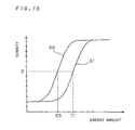
- Fig. 15 shows a correlation between the amount of energy provided to the recording material by the laser beam and a black density of the recording material.
- producing an image at a desired density D on a recording material having a gamma characteristic G0 requires irradiation of the recording material with a laser beam having an energy amount E0
- producing an image at a desired density D on a recording material having a gamma characteristic G1 requires irradiation of the recording material with a laser beam having an energy amount E1.
- the energy amount of a beam spot in general, shows a concentric intensity distribution.
- the developer temperature and the developing time are relatively easily controlled optimally by the developing apparatus. It has been, however, difficult to control the developer sensitivity to be held constant because of its characteristic. This presents a problem such that, even if the image recorder forms a correct latent image of dots on the recording material, the developing apparatus cannot correctly develop the recording material to fail to form dots of desired density and size on the recording material.
- the present invention is intended for an image recorder for recording information about a two-dimensional image made up of a plurality of dots on a recording material by relatively moving a laser spot in a main scanning direction and in a sub-scanning direction, the laser spot being formed on the recording material by irradiation with a laser beam.
- the image recorder comprises: a laser light source for emitting the laser beam; a laser light source drive part for driving the laser light source, based on an image signal; an input part for inputting factor information influencing the size of the dots; and a setting part for adjusting and setting a light emission duration per dot and a light emission amount of the laser light source in accordance with the factor information inputted by the input part.
- the image recorder can adjust and set the light emission duration per dot and the light emission amount of the laser light source to individually adjust the dimensions, in the main scanning direction and in the sub-scanning direction, of the dots to be formed on the recording material. This allows the proper recording of the information about the two-dimensional image even if a change occurs in the factor information influencing the dot dimensions to cause non-uniform changes in the dot dimensions in the main scanning direction and the sub-scanning direction.
- the factor information includes at least one of a first factor related to a characteristic of the recording material and a second factor related to processing of a recorded material.
- the image recorder further comprises an image signal correction part for correcting the image signal to be provided to the laser light source drive part, wherein the setting part is capable of providing a light emission timing correction signal for correcting the light emission duration of the laser light source to the image signal correction part, and of providing a light amount setting signal for setting the light emission amount of the laser light source to the laser light source drive part.
- the image recorder further comprises a memory for storing therein the factor information, the light emission timing correction signal and the light amount setting signal in corresponding relation to each other, wherein the setting part reads from the memory the light emission timing correction signal and the light amount setting signal corresponding to the factor information inputted by the input part.
- the present invention is also intended for a method of recording information about a two-dimensional image made up of a plurality of dots on a recording material by relatively moving a laser spot in a main scanning direction and in a sub-scanning direction, the laser spot being formed on the recording material by irradiation with a laser beam.
- a dimension (referred to hereinafter as a sub-scanning dimension) of a dot in a sub-scanning direction and a dimension (referred to hereinafter as a main scanning dimension) thereof in a main scanning direction are held constant independently of a change in the aforementioned various factors (the recording material sensitivity, the developer sensitivity, and the like) which influence the dot size. This is achieved by adjusting the balance between the factors.
- the developer sensitivity is lowered, this problem is not solved by a simple technique such as to increase the amount of light to compensate for the lowered developer sensitivity.
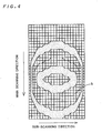
- Fig. 1 shows an example of the profile of a laser beam held stationary.
- a pulse having a waveform as shown in Fig. 2 is applied as a laser light source drive signal to drive a laser light source while moving the laser beam relative to a recording material
- energy having a distribution as shown in Fig. 3 is stored in the recording material.
- energy exceeding a blackening threshold is stored in a region indicated by the reference character b in Fig. 4 showing the energy storage resulting from the laser beam irradiation.
- the lowering of the developer sensitivity causes the region b to be insufficiently blackened, resulting in the formation of a dot having an insufficient size.
- the amount of light emitted from the laser light source may be increased to change the energy distribution of a beam spot.
- the adjustment of the amount of light emitted from the laser light source has different degrees of influence upon the main scanning dimension and the sub-scanning dimension, respectively, of the dot.
- the sub-scanning dimension of the region to be blackened is approximately equal to the dimension of a section, taken on the blackening threshold, of the energy distribution of a laser spot moving on the recording material.
- Fig. 5 shows the position of the laser beam in the sub-scanning direction (along the horizontal axis) versus the amount of energy stored by the laser beam directed onto various positions (along the vertical axis).
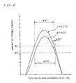
- Fig. 6 shows the position of the laser beam in the main scanning direction (along the horizontal axis) versus the amount of energy stored by the laser beam directed onto various positions (along the vertical axis). It is now assumed that a required sub-scanning dimension of a dot is WX0. A change in the developer sensitivity changes the amount of energy required to blacken the recording material (referred to simply as a "required energy amount" hereinafter).
- This increases the amount of energy stored in the recording material to provide a main scanning dimension WY1' approximately equal to an original main scanning dimension WY0 even if the developer sensitivity is lowered from the value C0 to the value C1.
- ⁇ WY the required main scanning dimension
- WY1' the main scanning dimension after only the adjustment of the amount of emitted light
- the deviation ⁇ WY of the main scanning dimension can be eliminated by adjusting a main scanning rate or adjusting the time duration of light emission from the laser light source per dot.
- the main scanning rate Assuming the main scanning rate to be V, increasing or decreasing (in the above example, increasing) the time duration of light emission from the laser light source per dot by an amount (assumed to be a correction amount ⁇ T) obtained by dividing the deviation ⁇ WY by the main scanning rate V allows the recording of a dot having a proper main scanning dimension as well on the recording material. This eliminates the deviation ⁇ WY without any influence upon the sub-scanning dimension of the dot.
- Fig. 7 shows a stored energy distribution in the main scanning direction when an output waveform of the laser light source drive signal is increased by the correction amount ⁇ T to eliminate the deviation ⁇ WY.
- the combination of adjustment items having different degrees of influence upon the main scanning dimension and the sub-scanning dimension allows the recording of a dot of proper size at all times.
- the change in the developer sensitivity is compensated for by the combination of the adjustment of the amount of emission of the laser beam and the adjustment of the time duration of light emission per dot in the above description, it is needless to say that a different combination of adjustment items may be used.
- the change in developer sensitivity may be compensated for by changing the amount of emission of the laser beam and the main scanning rate.
- the compensation for the change in the developer sensitivity is described above as an example, other changes may be compensated for.
- the present invention is applicable when a changes is made in the developer temperature and developing time in the developing apparatus or in the sensitivity of the recording material.
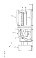
- Fig. 8 is a top view of an image recording system 1 to which the present invention is applied, and Fig. 9 is a side view thereof.
- the image recording system 1 comprises a plate supply apparatus 2, an image recorder 3 and an automatic developing apparatus 4.
- Plates for use in the image recording system 1 include a heat-sensitive material (generally referred to as a "thermal plate") which responds to heat generated by laser beam irradiation to record information about an image thereon.
- the plate supply apparatus 2 extracts a plate stored in a cassette 7 and transports the plate to a feed passage 11 of the image recorder 3. Typically, a plurality of plates are stored in the cassette 7.
- the image recorder 3 is provided to record information about a two-dimensional image comprised of a plurality of dots onto the plate supplied from the plate supply apparatus 2.
- the image recorder 3 comprises a recording drum 12 rotating with the supplied plate wound around an outer periphery thereof, a recording head 13 for irradiating the plate wound around the outer periphery of the recording drum 12 with a laser beam modulated in accordance with an image signal, and a discharge passage 14 for moving the information-recorded plate in a switch-backing manner to transport the information-recorded plate to the automatic developing apparatus 4 in the next stage.
- the automatic developing apparatus 4 develops with a developer the plate on which information about an image is recorded, and then dries the plate.
- the automatic developing apparatus 4 comprises a developer tank and a drying section both not shown.
- the automatic developing apparatus 4 performs feedback control so that the temperature of the developer in the developer tank and the developing time (the time required for the plate to pass through the developer tank and the drying section) are maintained constant.
- the plate stored in the cassette 7 of the plate supply apparatus 2 is transported to the image recorder 3 while part of the plate is fixedly held under suction by a movable suction arm 8 of an autoloader mechanism 6 in the plate supply apparatus 2.
- this plate passes through the feed passage 11 in the image recorder 3 and is wound around the outer periphery of the recording drum 12.
- the recording drum 12 rotates at high speeds.
- a laser light source incorporated in the recording head 13 irradiates a surface of the rotating plate wound around the recording drum 12 with the laser beam modulated in accordance with the image signal.
- the recording head 13 records information about an image in the main scanning direction of the plate.
- the recording head 13 also moves along the axis of rotation of the recording drum 12 in synchronism with the rotation of the recording drum.
- the recording head 13 records information about the image in the sub-scanning direction of the plate. In this manner, the information about a desired two-dimensional image is recorded on the surface of the plate.
- the plate on which the information about an image is recorded is transported through the discharge passage 14 of the image recorder 3 to the automatic developing apparatus 4.
- This plate is developed in the developer tank of the automatic developing apparatus 4, dried by the drying section, and is then discharged out of the automatic developing apparatus 4.
- the developer tank is equipped with a sensor 41 (see Fig. 10) for measuring the electric conductivity of the developer.
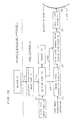
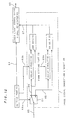
- Fig. 10 is a block diagram showing a construction of a processing section of the image recording system 1 to which the present invention is applied.
- the processing section includes the sensor 41 as an element included in the automatic developing apparatus 4.
- the processing section further includes a developer sensitivity input part 31, a plate type input part 32, a setting part 33, a memory 34, an image signal correction circuit 35, a laser light source drive signal generator 36 and a laser light source 37 all of which are elements included in the image recorder 3.
- the sensor 41 measures the electric conductivity 61 of the developer in the developer tank in the above-mentioned automatic developing apparatus 4. Since the electric conductivity, in general, is highly correlated with the developer sensitivity, the developer sensitivity is detected by measuring the electric conductivity of the developer.
- the developer sensitivity input part 31 inputs the electric conductivity 61 measured by the sensor 41 to the setting part 33.
- the plate type input part 32 inputs a plate type 62 of a plate 9 wounded around the recording drum 12, and includes a known keyboard or mouse.
- Fig. 11 shows the memory contents in the memory 34.
- the memory 34 stores therein the electric conductivity 61, a light emission timing correction signal 63 and a laser light amount signal 64 in corresponding relation to each plate type 62, the laser light amount signal 64 being provided for attaining the amount of light emitted from the laser light source 37 required to form dots of proper size.
- the plate types 62 in the memory 34 are classified according to the degree of response to laser irradiation or the developer, such as the above-mentioned gamma characteristic.
- An increase/decrease indication signal 63a and a correction amount indication signal 63b in the memory 34 constitute the above-mentioned light emission timing correction signal 63.
- the correction amount indication signal 63b is a signal for specifying the amount of delay of the image signal to be caused by delay circuits 52, 53 to be described later. The amount of delay corresponds to the above-mentioned correction amount ⁇ T.
- the setting part 33 inputs the electric conductivity 61 and the plate type 62 to the memory 34.
- the setting part 33 also sends the light emission timing correction signal 63 outputted from the memory 34 to the image signal correction circuit 35, and sends the laser light amount signal 64 to the laser light source drive signal generator 36.
- the image signal correction circuit 35 corrects an image signal 65 sent from an image processing apparatus not shown to output a corrected image signal 67.
- the laser light source drive signal generator 36 generates a laser light source drive signal 68, based on the corrected image signal 67 and the laser light amount signal 64.
- the laser light source 37 emits a laser beam 69, based on the laser light source drive signal 68.
- the image signal correction circuit 35 comprises a switch circuit 51, the delay circuits 52, 53, an AND gate 54 and an OR gate 55, as typically illustrated in Fig. 12.
- the light emission timing correction signal 63 includes the increase/decrease indication signal 63a and the correction amount indication signal 63b, as shown in Fig. 11.
- the increase/decrease indication signal 63a controls the switch circuit 51 to determine whether to send the image signal 65 inputted to the image signal correction circuit 35 to the delay circuit 52 and the AND gate 54 or to the delay circuit 53 and the OR gate 55.
- the correction amount indication signal 63b is sent to the delay circuits 52 and 53 to cause the image signal 65 inputted thereto via the switch circuit 51 to delay by a length of time corresponding to the above-mentioned correction amount ⁇ T.
- a decreasing correction is performed on the image signal 65.
- the increase/decrease indication signal 63a indicates "decrease (D)," and the image signal 65 is sent to a branch including the AND gate 54.
- an increasing correction is performed on the image signal 65.
- the increase/decrease indication signal 63a indicates "increase (A)," and the image signal 65 is sent to a branch including the OR gate 55.
- Fig. 13 is a diagram for illustrating the image signal correction when the image signal 65 is sent to the branch including the AND gate 54.
- the delay circuit 52 outputs a delayed image signal 66 which lags the delay time ⁇ T behind the image signal 65.
- the AND gate 54 performs an AND operation on the image signal 65 and the delayed image signal 66 to output the corrected image signal 67. It will be apparent from Fig. 13 that the corrected image signal 67 is shorter by the correction amount ⁇ T than the image signal 65.
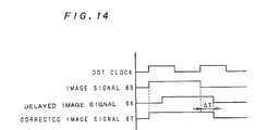
- Fig. 14 is a diagram for illustrating the image signal correction when the image signal 65 is sent to the branch including the OR gate 55.
- the delay circuit 53 outputs the delayed image signal 66 which lags the delay time ⁇ T behind the image signal 65.
- the OR gate 55 performs an OR operation on the image signal 65 and the delayed image signal 66 to output the corrected image signal 67. It will be apparent from Fig. 14 that the corrected image signal 67 is longer by the correction amount ⁇ T than the image signal 65.
- the corrected image signal 67 is outputted to the laser light source drive signal generator 36.
- the laser light source drive signal generator 36 generates the laser light source drive signal 68 for emitting a laser beam to be turned on/off by the corrected image signal 67 with power responsive to the laser light amount signal 64 sent from the setting part 33, thereby to drive the laser light source 37.
- the setting part 33 sets conditions depending on the change for the image signal correction circuit 35 and the laser light source drive signal generator 36 which in turn adjust the image signal 65 and the laser beam amount, respectively. Therefore, the image recording system 1 is capable of always recording a high-quality image on the plate (recording material).
- the present invention is not limited to such a configuration.
- the automatic developing apparatus 4 may develop a sample (known as a control strip) on which a standard image of stepwise varying densities is formed, thereby to measure the sensitivity of the developer.
- the sensor 41 is not used, but a user manually enters a value indicating the sensitivity of the developer through an input part including a known keyboard or mouse.
- the image recorder 3 is of the external drum recording type in the above-mentioned preferred embodiment, it is needless to say that the present invention is also applicable to an internal drum recording type and to a plane scanning type. Thus, the present invention is widely applicable independently of recording methods.
Landscapes
- Engineering & Computer Science (AREA)
- Multimedia (AREA)
- Signal Processing (AREA)
- Physics & Mathematics (AREA)
- Optics & Photonics (AREA)
- Fax Reproducing Arrangements (AREA)
- Laser Beam Printer (AREA)
- Facsimile Scanning Arrangements (AREA)
- Manufacture Or Reproduction Of Printing Formes (AREA)
- Projection-Type Copiers In General (AREA)
- Control Of Exposure In Printing And Copying (AREA)
Abstract
Description
Claims (15)
- An image recorder for recording information about a two-dimensional image made up of a plurality of dots on a recording material by relatively moving a laser spot in a main scanning direction and in a sub-scanning direction, said laser spot being formed on said recording material by irradiation with a laser beam, said image recorder comprising:a laser light source for emitting said laser beam;a laser light source drive part for driving said laser light source, based on an image signal;an input part for inputting factor information influencing the size of said dots; anda setting part for adjusting and setting a light emission duration per dot and a light emission amount of said laser light source in accordance with said factor information inputted by said input part.
- The image recorder according to claim 1, wherein
said factor information includes at least one of a first factor related to a characteristic of said recording material and a second factor related to processing of a recorded material. - The image recorder according to claim 2, further comprising
an image signal correction part for correcting said image signal to be provided to said laser light source drive part,
wherein said setting part is capable of providing a light emission timing correction signal for correcting the light emission duration per dot of said laser light source to said image signal correction part, and of providing a light amount setting signal for setting the light emission amount of said laser light source to said laser light source drive part. - The image recorder according to claim 3, further comprising
a memory for storing therein said factor information, said light emission timing correction signal and said light amount setting signal in corresponding relation to each other,
wherein said setting part reads from said memory said light emission timing correction signal and said light amounts setting signal corresponding to said factor information inputted by said input part. - The image recorder according to claim 4, wherein
the processing of said recorded material includes a developing process of said recorded material. - The image recorder according to claim 5, wherein
said second factor includes information indicating the sensitivity of a developer for use in said developing process. - The image recorder according to claim 4, wherein
said recording material includes a heat-sensitive material responsive to heat generated by irradiation with said laser beam. - The image recorder according to claim 7, wherein
said first factor includes information indicating the sensitivity of said recording material. - A method of recording information about a two-dimensional image made up of a plurality of dots on a recording material by relatively moving a laser spot in a main scanning direction and in a sub-scanning direction, said laser spot being formed on said recording material by irradiation with a laser beam, said method comprising the steps of:inputting factor information influencing the size of said dots;adjusting and setting an emission duration per dot and an emission amount of said laser beam in accordance with said factor information inputted; andemitting said laser beam, based on said emission duration per dot and said emission amount both adjusted and set.
- The method according to claim 9, wherein
said factor information includes at least one of a first factor related to a characteristic of said recording material and a second factor related to processing of a recorded material. - The method according to claim 10, further comprising the step of
reading, from a memory for storing therein said factor information, a light emission timing correction signal for correcting the emission duration per dot of said laser beam and a light amount setting signal for setting the emission amount of said laser beam in corresponding relation to each other, said light emission timing correction signal and said light amount setting signal corresponding to said factor information inputted. - The method according to claim 11, wherein
the processing of said recorded material includes a developing process of said recorded material. - The method according to claim 12, wherein
said second factor includes information indicating the sensitivity of a developer for use in said developing process. - The method according to claim 11, wherein
said recording material includes a heat-sensitive material responsive to heat generated by irradiation with said laser beam. - The method according to claim 14, wherein
said first factor includes information indicating the sensitivity of said recording material.
Applications Claiming Priority (2)
| Application Number | Priority Date | Filing Date | Title |
|---|---|---|---|
| JP2001199082 | 2001-06-29 | ||
| JP2001199082A JP2003011419A (en) | 2001-06-29 | 2001-06-29 | Image recorder |
Publications (2)
| Publication Number | Publication Date |
|---|---|
| EP1274226A2 true EP1274226A2 (en) | 2003-01-08 |
| EP1274226A3 EP1274226A3 (en) | 2007-03-14 |
Family
ID=19036423
Family Applications (1)
| Application Number | Title | Priority Date | Filing Date |
|---|---|---|---|
| EP02013264A Withdrawn EP1274226A3 (en) | 2001-06-29 | 2002-06-17 | Image recorder and method of recording image |
Country Status (3)
| Country | Link |
|---|---|
| US (1) | US6724415B2 (en) |
| EP (1) | EP1274226A3 (en) |
| JP (1) | JP2003011419A (en) |
Families Citing this family (4)
| Publication number | Priority date | Publication date | Assignee | Title |
|---|---|---|---|---|
| US6981447B2 (en) * | 2003-04-09 | 2006-01-03 | Esko-Graphics A/S | Method and apparatus for loading and unloading flexographic plates for computer-to-plate imaging |
| US7000543B2 (en) * | 2003-04-09 | 2006-02-21 | Esko-Graphics A/S | Method and apparatus for loading and unloading flexographic plates for computer-to-plate imaging |
| JP4948203B2 (en) * | 2007-02-26 | 2012-06-06 | 大日本スクリーン製造株式会社 | Image recording device |
| US9381752B2 (en) * | 2014-03-28 | 2016-07-05 | Kyocera Document Solutions Inc. | Information processing apparatus and laser irradiation apparatus |
Family Cites Families (6)
| Publication number | Priority date | Publication date | Assignee | Title |
|---|---|---|---|---|
| US5270736A (en) * | 1989-09-19 | 1993-12-14 | Canon Kabushiki Kaisha | Light modulation method |
| EP0558078B1 (en) * | 1992-02-27 | 1997-01-15 | Fuji Photo Film Co., Ltd. | Thermal recording system |
| US5786994A (en) * | 1994-11-23 | 1998-07-28 | Imation Corp. | Performance monitoring system and method for a laser medical imager |
| JPH09130605A (en) * | 1995-10-31 | 1997-05-16 | Fuji Photo Film Co Ltd | Halftone image output method and apparatus |
| US6130700A (en) * | 1996-07-09 | 2000-10-10 | Cycolor Systems, Inc. | Aligner, exposure method and printer |
| US6803937B2 (en) * | 2000-05-23 | 2004-10-12 | Noritsu Koki Co., Ltd. | Photographic printer having varied intensities or optical modulation data for laser light sources |
-
2001
- 2001-06-29 JP JP2001199082A patent/JP2003011419A/en active Pending
-
2002
- 2002-06-17 EP EP02013264A patent/EP1274226A3/en not_active Withdrawn
- 2002-06-20 US US10/175,380 patent/US6724415B2/en not_active Expired - Lifetime
Also Published As
| Publication number | Publication date |
|---|---|
| JP2003011419A (en) | 2003-01-15 |
| EP1274226A3 (en) | 2007-03-14 |
| US6724415B2 (en) | 2004-04-20 |
| US20030001946A1 (en) | 2003-01-02 |
Similar Documents
| Publication | Publication Date | Title |
|---|---|---|
| EP0529540A2 (en) | Electronic drive circuit for multi-laser thermal printer | |
| US7196717B2 (en) | Image forming apparatus, control method therefor, and program for implementing the control method | |
| US20050013644A1 (en) | Print media edge detection method and apparatus | |
| JPS61137760A (en) | Thermal recording device and method | |
| US11562188B2 (en) | Printed image inspection device and printing apparatus including same | |
| US6724415B2 (en) | Image recorder and method of recording image | |
| US8447196B2 (en) | Recording material determination apparatus and image forming apparatus having a determining unit that determines an attribute of a recording material | |
| JPH01257868A (en) | Information printing device | |
| JPH05212900A (en) | Image forming method | |
| US4984015A (en) | Exposure method and apparatus | |
| JPS63209270A (en) | Droop corrector for semiconductor laser | |
| US4928277A (en) | Method and apparatus for driving laser beam source to avoid droop effects | |
| US6956639B2 (en) | Image processing apparatus, image processing method and program | |
| US7180533B2 (en) | Image processing apparatus, image processing method, and program | |
| US6072513A (en) | Method of density correction and an image recording apparatus | |
| JPH04179370A (en) | Density correction device in picture recording device | |
| JP2005202217A (en) | Image recording device and image recording method | |
| JP4471333B2 (en) | Image forming apparatus | |
| JP3951923B2 (en) | Thermal development apparatus and thermal development method | |
| JPS63204522A (en) | Laser recorder | |
| JP2003011419A5 (en) | ||
| US6117625A (en) | Method and apparatus for creating a composite image by the tiling of multiple image frames | |
| JPS6372264A (en) | Scanning fluctuation correcting method | |
| JPH06135037A (en) | Thermal laser printer | |
| JPH05153352A (en) | Recording method and laser recording device |
Legal Events
| Date | Code | Title | Description |
|---|---|---|---|
| PUAI | Public reference made under article 153(3) epc to a published international application that has entered the european phase |
Free format text: ORIGINAL CODE: 0009012 |
|
| AK | Designated contracting states |
Kind code of ref document: A2 Designated state(s): AT BE CH CY DE DK ES FI FR GB GR IE IT LI LU MC NL PT SE TR |
|
| AX | Request for extension of the european patent |
Free format text: AL;LT;LV;MK;RO;SI |
|
| PUAL | Search report despatched |
Free format text: ORIGINAL CODE: 0009013 |
|
| AK | Designated contracting states |
Kind code of ref document: A3 Designated state(s): AT BE CH CY DE DK ES FI FR GB GR IE IT LI LU MC NL PT SE TR |
|
| AX | Request for extension of the european patent |
Extension state: AL LT LV MK RO SI |
|
| RIC1 | Information provided on ipc code assigned before grant |
Ipc: G06K 15/12 20060101ALI20070208BHEP Ipc: H04N 1/40 20060101AFI20020917BHEP |
|
| 17P | Request for examination filed |
Effective date: 20070614 |
|
| AKX | Designation fees paid |
Designated state(s): AT BE CH CY DE DK ES FI FR GB GR IE IT LI LU MC NL PT SE TR |
|
| 17Q | First examination report despatched |
Effective date: 20071106 |
|
| STAA | Information on the status of an ep patent application or granted ep patent |
Free format text: STATUS: THE APPLICATION IS DEEMED TO BE WITHDRAWN |
|
| 18D | Application deemed to be withdrawn |
Effective date: 20080318 |