EP1274188A1 - Method for monitoring a redundant transmitter - Google Patents
Method for monitoring a redundant transmitter Download PDFInfo
- Publication number
- EP1274188A1 EP1274188A1 EP01116450A EP01116450A EP1274188A1 EP 1274188 A1 EP1274188 A1 EP 1274188A1 EP 01116450 A EP01116450 A EP 01116450A EP 01116450 A EP01116450 A EP 01116450A EP 1274188 A1 EP1274188 A1 EP 1274188A1
- Authority
- EP
- European Patent Office
- Prior art keywords
- transmitter
- redundant
- receivers
- spread
- signal
- Prior art date
- Legal status (The legal status is an assumption and is not a legal conclusion. Google has not performed a legal analysis and makes no representation as to the accuracy of the status listed.)
- Granted
Links
- 238000000034 method Methods 0.000 title claims abstract description 42
- 238000012544 monitoring process Methods 0.000 title claims abstract description 12
- 238000001228 spectrum Methods 0.000 claims abstract description 16
- 238000004891 communication Methods 0.000 claims abstract description 13
- 230000003595 spectral effect Effects 0.000 claims abstract description 5
- 238000010408 sweeping Methods 0.000 claims description 17
- 230000005540 biological transmission Effects 0.000 claims description 15
- 238000005070 sampling Methods 0.000 claims description 10
- 230000000694 effects Effects 0.000 claims description 9
- 238000004364 calculation method Methods 0.000 claims description 6
- 238000001514 detection method Methods 0.000 claims description 5
- 238000012545 processing Methods 0.000 claims description 4
- 238000010586 diagram Methods 0.000 description 10
- 230000015556 catabolic process Effects 0.000 description 6
- 238000006731 degradation reaction Methods 0.000 description 6
- 230000002950 deficient Effects 0.000 description 2
- 238000007493 shaping process Methods 0.000 description 2
- 230000001360 synchronised effect Effects 0.000 description 2
- 239000002699 waste material Substances 0.000 description 2
- 238000012935 Averaging Methods 0.000 description 1
- 230000001154 acute effect Effects 0.000 description 1
- 230000002411 adverse Effects 0.000 description 1
- 238000013459 approach Methods 0.000 description 1
- 230000009286 beneficial effect Effects 0.000 description 1
- 238000007796 conventional method Methods 0.000 description 1
- 238000005314 correlation function Methods 0.000 description 1
- 230000002939 deleterious effect Effects 0.000 description 1
- 238000011161 development Methods 0.000 description 1
- 238000001914 filtration Methods 0.000 description 1
- 238000013507 mapping Methods 0.000 description 1
- 238000005259 measurement Methods 0.000 description 1
- 230000001131 transforming effect Effects 0.000 description 1
Images


Classifications
-
- H—ELECTRICITY
- H04—ELECTRIC COMMUNICATION TECHNIQUE
- H04W—WIRELESS COMMUNICATION NETWORKS
- H04W24/00—Supervisory, monitoring or testing arrangements
- H04W24/04—Arrangements for maintaining operational condition
-
- H—ELECTRICITY
- H04—ELECTRIC COMMUNICATION TECHNIQUE
- H04B—TRANSMISSION
- H04B17/00—Monitoring; Testing
- H04B17/10—Monitoring; Testing of transmitters
- H04B17/15—Performance testing
- H04B17/18—Monitoring during normal operation
Definitions
- the invention relates to a method for monitoring a redundant transmitter in a radio communications system having an active transmitter and one or more receivers.
- the method is particularly applicable to point-to-multipoint radio communications systems.
- Radio transmission systems are often used to transmit data.
- a common scenario is the transmission of data from a base station to a number of receivers in a point-to-multipoint system.
- the base station BS communicates with a number of terminal stations TS1-TS3 in one particular sector 10 of the base station's range.
- the active and redundant equipments are basically identical and comprise an indoor part (IDU) and a cable-linked outdoor part (ODU).
- the ODU includes an RF stage and an antenna 11. Where failure of the active transmitter occurs, the redundant transmitter can take over the transmission of data.
- the invention provides a third possibility for transmitting a pilot (or monitoring) signal over the redundant transmitter without disturbing the data signal being transmitted by the active transmitter.
- a spread-spectrum (SS) signal within the frequency band of the data signal, but with very low spectral power, is transmitted over the redundant transmitter.
- the receiver also contains means for specifically detecting the SS signal and, if it is not present, it can be concluded that the redundant transmitter is defective.
- the advantage of the invention is its universal applicability (it does not depend on the nature of the data signal), the fact that it does not waste time or frequency resources, and its susceptability to digital realisation, so that it is also cost-effective. Further, the ODU does not have to be specially designed and no measurement setup or link between the ODU and the IDU has to be provided. The principle can be applied not only to point-to-multipoint systems but also to point-to-point systems having redundancy.
- Figure 3 is a block diagram of a radio link featuring the monitoring method of the invention and includes both active and redundant (passive) paths in the transmitter and the receiver.
- the transmission stages are the same in both paths and include a mapping stage 12, and interpolation stage 13, a digital-to-analogue converter stage 14 and an IF/RF output stage 15 which feeds an antenna 16.
- the modulation scheme which is used is a linear one, e.g. quadrature amplitude modulation.
- the bits which are to be transmitted are first mapped into channel symbols in the mapper 12. Assuming, for example, that a 4QAM or a QPSK modulation scheme is employed, the channel symbols are made to correspond to one of the four points in the complex plane shown in Figure 4, i.e. two bits of the wanted data bitstream to be transmitted are mapped onto one of these four symbols, yielding for that symbol two complex values (real and imaginary) at the output of the mapper. There then occurs a pulse-shaping process using a square-root nyquist filter. The output of this filter is sampled and converted into analogue form (14).
- the sampling rate must be at least twice the channel symbol rate, and therefore an oversampling factor-of- ⁇ interpolation function is performed, which is included in the pulse-shaping block 13.
- the baseband signal is upconverted to IF and then RF (15) before being transmitted from the antenna 16.
- the data signal is transmitted over the active path.
- a switch 17 is provided which makes it possible during normal operation to feed in a spread-spectrum (SS) signal at symbol rate, but, following failure of the active transmitter, to take over transmission of the data signal.
- SS spread-spectrum
- the SS signal consists of a long pseudo-noise sequence ( ⁇ 1 in amplitude) of length N pn .
- the signal is upsampled with an oversampling factor ⁇ .
- the SS signal will have the same bandwidth as the data signal. However at the air interface its spectral density will be significantly lower than the density of the data signal (about 30-35 dB lower). Thus, for the data signal the PN sequence appears only as an additional, but negligible, white noise.
- the signal received at the receiver antenna 18 is downconverted again to baseband (19) and changed from analogue form to digital (20), following which a corresponding interpolation step is performed (21), the resulting signal being, in accordance with conventional methods, subject to a synchronisation and equalisation process (22), thereby producing the data signal originally transmitted by the active transmitter.
- steps are taken to detect the SS signal that is being transmitted by the redundant transmitter. This is achieved by correlating the received signal with the same PN sequence that was used by the transmitter. This is shown by the separate branch 23, which is taken to the correlation stage 24, the result of the correlation process being used to make a decision as to whether or not the SS signal was received.
- the received signal comprises both the transmitted data signal and the SS signal). In practice it is the maximum of the absolute value of the correlation which is used to form the decision.
- Figure 5 shows the simplified link from Figure 3.
- r k and s k are the data signal and the SS signal respectively, both oversampled with ⁇ .
- the simplification of concentrating all filters at the beginning of the transmission path and all frequency offsets at the end is based on the fact that filtering and frequency offset can be interchanged if the filter bandwidth of the receiver filter is large compared to the frequency offset and if the frequency offset is small compared to changes of the filter function in the frequency domain.
- ⁇ s 2 is the variance (or power) of the SS signal.
- the SS signal would not be detected.
- ⁇ P there is a region for ⁇ P where detection is possible, i.e. where the degradation can be tolerated.
- the correlation length has to be quite large in order to detect the SS signal with its very low power, so the acceptable ⁇ P is too small.
- the proposed solution according to the invention is to carry out a "sweeping" process, where an intentional and stepwise changing frequency offset ⁇ S is introduced before the correlator.
- the correlation is calculated for a number N d of offsets, thus covering the whole range of ⁇ P .
- Figure 7 reproduces the simplifed model of Figure 5, but this time with the additional sweeping. It should be noted that the correlator output is now two-dimensional, being a function of n and ⁇ S .
- ⁇ 0 be the frequency offset with acceptable degradation. If the stepsize is 2 ⁇ 0 , then one of the resulting offsets
- each offset is applied in turn, each offset being effective for an actual frequency offset of ⁇ 0 about that applied offset.
- Each ⁇ S is applied for a time ⁇ t 0 , this being the time over which correlation takes place for that value of ⁇ S .
- the invention provides for the sweeping steps to be adapted so that the regions ⁇ S (i) - ⁇ 0 ... ⁇ S (i) + ⁇ 0 overlap, as shown now in Figure 10.
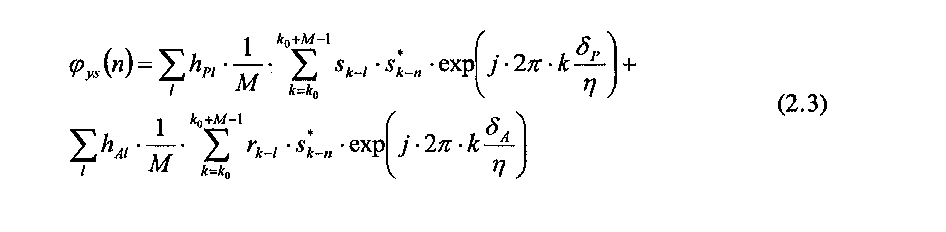
- EMBED h Pl is the discrete impulse response of the passive transmission path, including all filters from the square-root nyquist filter 13 at the transmitter to the similar filter 21 at the receiver (see Figure 3).
- phase error appears to behave like a sampling phase error with the discrete-time representation of h P (t) .
- the mean value of the correlator output will be:
- the crosscorrelation of the received signal and the PN sequence has to be calculated for N d sweeping points, in addition to the ⁇ N pn "time" points.
- ⁇ 2 is assumed.
- Figure 11 shows the principle of the correlation unit: the received signal y k+k0 is rotated by a complex factor exp(j ⁇ S ( i ) k ) and then multiplied by the over-sampled output of the same shift register, as in the transmitter. M values at a time are accumulated (M is the correlation length), the division by M giving the crosscorrelation:
- All serial means that the points in the two dimensional space ( n , i ) are calculated one after another.
- All parallel means that all values of ⁇ ( n , i ) are calculated at once.
- the all-serial method requires the least outlay in terms of hardware, but is slow; the all-parallel method is fast, but incurs greater hardware outlay.
- the preferred embodiment of the invention employs a compromise solution, in which calculations are carried out in a partly serial, partly parallel manner. This brings with it a trade-off between speed and outlay.
- N S 8.
- the first N S / 2 i.e. 4 values of the shift register are read out.
- the described principle of monitoring a redundant transmitter by a SS signal can be used for point-to-point systems as well as for point-to-multipoint systems. However, in point-to-multipoint systems the following additional and beneficial feature can be introduced.
- Each terminal makes a decision as to whether the SS signal is present or not and the decision is transmitted to the base station. Only if a predetermined number of terminals indicated that the SS signal had not been received is an alarm then given to the network management system. Preferably the alarm is only given where at least half of all the terminals gave a negative report, i.e. majority voting.
- Such averaging over all the terminals allows the requirements of the correlator in each terminal to be relaxed (the correlation length may be reduced, for example), without reducing the reliability of the supervision.
Landscapes
- Engineering & Computer Science (AREA)
- Computer Networks & Wireless Communication (AREA)
- Signal Processing (AREA)
- Physics & Mathematics (AREA)
- Electromagnetism (AREA)
- Mobile Radio Communication Systems (AREA)
- Small-Scale Networks (AREA)
- Maintenance And Management Of Digital Transmission (AREA)
Abstract
Description
- the data signal uses both transmitters (active and redundant) at different frequencies or time slots. This is possible only in point-to-multipoint systems if the data signal in the downlink is bursty, i.e. if different time slots are employed for different terminals, or if it is an FDM (frequency division multiplex) signal, i.e.different frequency bands are used for different terminals.
- a pilot signal is transmitted over the redundant transmitter, either in the time or frequency domain. This is, however, a waste of resources.
- the outdoor unit (ODU) is self-monitoring, i.e. the supervision is performed only at the analog part of the transmitter, for example by monitoring the oscillators. This requires a special development of the redundant ODU and a digital link between the redundant ODU and IDU (indoor unit). Further, this involves additional hardware outlay, which can be costly.








Claims (30)
- A method for monitoring the redundant transmitter of a radio communications system, which system comprises an active transmitter for the transmission of data signals to one or more receivers, the method comprising the steps of:(a) during normal operation transmitting over the redundant transmitter a spread-spectrum signal, said spread-spectrum signal being of low spectral power in comparison with said data signals;(b) at one or more of the one or more receivers, detecting the presence of the spread-spectrum signal, the absence thereof being taken to indicate the non-integrity of the redundant transmitter.
- Method as claimed in Claim 1, wherein detection is performed by a process of correlation.
- Method as claimed in Claim 2, wherein detection is performed by a process of cross-correlation, the spread-spectrum signal being provided by feeding the redundant transmitter with a first pseudo-noise signal and the cross-correlation being performed between the received signal and a second pseudo-noise signal, the second pseudo-noise signal having the same characteristics as the first.
- Method as claimed in Claim 3, wherein the first pseudo-noise signal passes through the same components in the redundant transmitter as would data signals, were the redundant transmitter called upon to take over from the active transmitter.
- Method as claimed in Claim 4, wherein, in order to compensate for a timing phase error in respect of the spread-spectrum signal, oversampling of the received signal is performed in the receiver.
- Method as claimed in Claim 5, wherein, in order to compensate for the effects of a frequency offset existing between the active and redundant transmitters and to take into account the narrow allowable window of offset which the correlation of a long pseudo-noise sequence can tolerate, the received signal is subjected to a stepped sweeping operation, wherein the received function is multiplied by a complex factor having the form exp{j2πkδ S /η}, where k is the sampling index, η is an oversampling factor and δ S are the sweeping steps, scaled by the symbol rate.
- Method as claimed in Claim 6, wherein the sweeping steps are chosen such as to cover all values of the frequency offset.
- Method as claimed in Claim 7, wherein the sweeping steps are chosen such as to compensate for a drift of the frequency offset with time.
- Method as claimed in Claim 8, wherein the cross-correlation is two-dimensional, being calculated for all sweeping steps δ S and for ηN pn time steps, where η is the oversampling factor and N pn is the length of the pseudo-noise sequence.
- Method as claimed in Claim 9, wherein a maximum of the absolute value of the cross-correlation result is employed to determine the integrity of the redundant transmitter.
- Method as claimed in Claim 9, wherein a maximum of the squared absolute value of the cross-correlation result is employed to determine the integrity of the redundant transmitter.
- Method as claimed in any one of Claims 9 to 11, wherein the correlation calculation is performed by a part-serial, part-parallel processing of the sampled data.
- Method as claimed in Claim 12, wherein said processing takes the form of a processing of a first group (N S ) of the ηN pn points in parallel for successive values of δ S , then of a second group (N S ) of the ηN pn points in parallel for successive values of δ S , and so on until all ηN pn points have been covered.
- Method as claimed in any one of the preceding claims, wherein the radio communications system comprises two or more receivers, each of which provides an indication of the presence or absence of the spread-spectrum signal, the decision as to the non-integrity of the redundant transmitter being taken on the basis of the indications of a predetermined number of the two or more receivers.
- Method as claimed in Claim 14, wherein the decision is taken on the basis of a majority vote.
- Method as claimed in Claim 14, wherein the radio communications system comprises one receiver and the indication of non-detection of the spread-spectrum signal at that receiver is taken as an indication of the non-integrity of the redundant transmitter.
- Method as claimed in any one of the preceding claims, wherein the radio communications system is a point-to-multipoint system, the active and redundant transmitters being part of a base station, and the receivers being terminal stations, of that point-to-multipoint system.
- Method as claimed in Claim 17, wherein the point-to-multipoint system is one of a group comprising: a TDM/TDMA system, an FDM/FDMA system and a CDM/CDMA system.
- Apparatus for monitoring the redundant transmitter of a radio transmission system, which system comprises an active transmitter for the transmission of data signals to one or more receivers, the apparatus comprising: means for generating a pseudo-noise signal; means for applying said pseudo-noise signal to an input of the redundant transmitter, the transmitter thereby transmitting a spread-spectrum signal having a low spectral power in comparison with said data signals; and means in one or more of the one or more receivers for detecting the presence of the spread-spectrum signal.
- Apparatus as claimed in Claim 19 comprising a correlator means in the one or more receivers for the cross-correlation of the received signal.
- Apparatus as claimed in Claim 20, comprising an oversampling means in the one or more receivers for the compensation of a timing phase error in respect of the spread-spectrum signal.
- Apparatus as claimed in Claim 21, comprising a sweeping means for subjecting the received signal to a frequency-sweeping operation, the sweeping means comprising a multiplier means for multiplying the received signal by a complex factor having the form exp{j2πkδ S /η}, where k is the sampling index, η is an oversampling factor and δ S are the sweeping steps, scaled by the symbol rate.
- Apparatus as claimed in Claim 22, wherein the correlator means is connected to a maximum-deriving means for deriving a maximum value of the correlator output.
- Apparatus as claimed in Claim 23, wherein the maximum-deriving means is arranged to derive the maximum of the absolute value of the correlator output.
- Apparatus as claimed in Claim 23, wherein the maximum-deriving means is arranged to derive the maximum of the square of the absolute value of the correlator output.
- A radio communications system comprising an active and a redundant transmitter, two or more receivers and an apparatus as claimed in any one of Claims 21 to 27.
- System as claimed in Claim 26, wherein the monitoring apparatus comprises a decision-making means fed by the indications of redundant-transmitter integrity delivered by the receivers.
- System as claimed in Claim 27, wherein the decision-making means makes a decision on the basis of majority voting among the receivers.
- System as claimed in any one of Claims 26 to 28, wherein the system is a point-to-multipoint system.
- System as claimed in Claim 29, wherein the system is one of a group comprising: a TDM/TDMA system, an FDM/FDMA system and a CDM/CDMA system.
Priority Applications (6)
| Application Number | Priority Date | Filing Date | Title |
|---|---|---|---|
| DE60123938T DE60123938T2 (en) | 2001-07-06 | 2001-07-06 | Method for monitoring a redundant transmitter |
| EP01116450A EP1274188B1 (en) | 2001-07-06 | 2001-07-06 | Method for monitoring a redundant transmitter |
| AT01116450T ATE343268T1 (en) | 2001-07-06 | 2001-07-06 | METHOD FOR MONITORING A REDUNDANT TRANSMITTER |
| PCT/IB2002/003215 WO2003005615A1 (en) | 2001-07-06 | 2002-06-27 | Method and apparatus for monitoring a redundant (standby) transmitter in a radio communications system |
| US10/482,794 US7773661B2 (en) | 2001-07-06 | 2002-06-27 | Method and apparatus for monitoring a redundant (standby) transmitter in a radio communications system |
| CNB028171667A CN100449968C (en) | 2001-07-06 | 2002-06-27 | Method and apparatus for monitoring redundant (standby) transmitters in a radio communication system |
Applications Claiming Priority (1)
| Application Number | Priority Date | Filing Date | Title |
|---|---|---|---|
| EP01116450A EP1274188B1 (en) | 2001-07-06 | 2001-07-06 | Method for monitoring a redundant transmitter |
Publications (2)
| Publication Number | Publication Date |
|---|---|
| EP1274188A1 true EP1274188A1 (en) | 2003-01-08 |
| EP1274188B1 EP1274188B1 (en) | 2006-10-18 |
Family
ID=8177968
Family Applications (1)
| Application Number | Title | Priority Date | Filing Date |
|---|---|---|---|
| EP01116450A Expired - Lifetime EP1274188B1 (en) | 2001-07-06 | 2001-07-06 | Method for monitoring a redundant transmitter |
Country Status (6)
| Country | Link |
|---|---|
| US (1) | US7773661B2 (en) |
| EP (1) | EP1274188B1 (en) |
| CN (1) | CN100449968C (en) |
| AT (1) | ATE343268T1 (en) |
| DE (1) | DE60123938T2 (en) |
| WO (1) | WO2003005615A1 (en) |
Cited By (1)
| Publication number | Priority date | Publication date | Assignee | Title |
|---|---|---|---|---|
| EP2861008A4 (en) * | 2012-06-25 | 2015-08-26 | Huawei Tech Co Ltd | ALARM DEVICE AND METHOD |
Families Citing this family (3)
| Publication number | Priority date | Publication date | Assignee | Title |
|---|---|---|---|---|
| DE10351649B9 (en) * | 2003-11-05 | 2008-08-07 | Infineon Technologies Ag | Method and device for synchronizing a mobile radio receiver with a base station |
| KR100692595B1 (en) | 2005-03-29 | 2007-03-13 | 삼성전자주식회사 | Signal Multiplexing System and Method Using Frequency Division Multiplexing and Code Division Multiplexing |
| TWI390890B (en) * | 2009-04-15 | 2013-03-21 | Realtek Semiconductor Corp | Frequency offset acquisition method and apparatus thereof |
Citations (4)
| Publication number | Priority date | Publication date | Assignee | Title |
|---|---|---|---|---|
| US4274156A (en) * | 1978-01-18 | 1981-06-16 | Bird Electronic Corporation | Monitor for RF transmitter |
| JPH03247022A (en) * | 1990-02-23 | 1991-11-05 | Fujitsu Ltd | Monitor system of standby channel for hot standby radio equipment |
| EP0930734A1 (en) * | 1997-12-18 | 1999-07-21 | Société Européenne des Satellites S.A. | Method and apparatus for determining characterics of components of a communication channel under load |
| US6188876B1 (en) * | 1998-01-28 | 2001-02-13 | Fine Digital, Inc. | System and method for remote monitoring of RF units in base station of wireless communication network |
Family Cites Families (13)
| Publication number | Priority date | Publication date | Assignee | Title |
|---|---|---|---|---|
| US4274456A (en) * | 1979-12-06 | 1981-06-23 | Coors Container Company | Apparatus for dispensing fluid sealant |
| US5022047A (en) * | 1989-08-07 | 1991-06-04 | Omnipoint Data Corporation | Spread spectrum correlator |
| US5287388A (en) * | 1991-06-25 | 1994-02-15 | Kabushiki Kaisha Toshiba | Frequency offset removal method and apparatus |
| WO1995012945A1 (en) * | 1993-11-01 | 1995-05-11 | Omnipoint Corporation | Despreading/demodulating direct sequence spread spectrum signals |
| JP3247022B2 (en) | 1995-01-06 | 2002-01-15 | 日立造船株式会社 | Wave power generator |
| WO1996032825A1 (en) * | 1995-04-12 | 1996-10-17 | Motorola Inc. | Method and system for providing communications service to a coverage hole |
| JP2728034B2 (en) * | 1995-06-15 | 1998-03-18 | 日本電気株式会社 | Spread spectrum signal receiver |
| US6697350B2 (en) * | 1995-06-30 | 2004-02-24 | Interdigital Technology Corporation | Adaptive vector correlator for spread-spectrum communications |
| US6160841A (en) * | 1996-05-24 | 2000-12-12 | Leica Geosystems Inc. | Mitigation of multipath effects in global positioning system receivers |
| US6438359B1 (en) * | 1996-07-19 | 2002-08-20 | Cellularvision Technology & Telecommunications, L.P. | Dual transmitter arrangement with back-up switching |
| US5960040A (en) * | 1996-12-05 | 1999-09-28 | Raytheon Company | Communication signal processors and methods |
| US6363105B1 (en) * | 1998-02-17 | 2002-03-26 | Ericsson Inc. | Flexible sliding correlator for direct sequence spread spectrum systems |
| US6392960B1 (en) * | 2000-08-25 | 2002-05-21 | Richard A. Seltzer | Acoustic communication of coded multi-channel digital messages in a liquid medium |
-
2001
- 2001-07-06 AT AT01116450T patent/ATE343268T1/en not_active IP Right Cessation
- 2001-07-06 EP EP01116450A patent/EP1274188B1/en not_active Expired - Lifetime
- 2001-07-06 DE DE60123938T patent/DE60123938T2/en not_active Expired - Lifetime
-
2002
- 2002-06-27 WO PCT/IB2002/003215 patent/WO2003005615A1/en not_active Ceased
- 2002-06-27 CN CNB028171667A patent/CN100449968C/en not_active Expired - Fee Related
- 2002-06-27 US US10/482,794 patent/US7773661B2/en active Active
Patent Citations (4)
| Publication number | Priority date | Publication date | Assignee | Title |
|---|---|---|---|---|
| US4274156A (en) * | 1978-01-18 | 1981-06-16 | Bird Electronic Corporation | Monitor for RF transmitter |
| JPH03247022A (en) * | 1990-02-23 | 1991-11-05 | Fujitsu Ltd | Monitor system of standby channel for hot standby radio equipment |
| EP0930734A1 (en) * | 1997-12-18 | 1999-07-21 | Société Européenne des Satellites S.A. | Method and apparatus for determining characterics of components of a communication channel under load |
| US6188876B1 (en) * | 1998-01-28 | 2001-02-13 | Fine Digital, Inc. | System and method for remote monitoring of RF units in base station of wireless communication network |
Non-Patent Citations (1)
| Title |
|---|
| PATENT ABSTRACTS OF JAPAN vol. 016, no. 038 (E - 1161) 30 January 1992 (1992-01-30) * |
Cited By (1)
| Publication number | Priority date | Publication date | Assignee | Title |
|---|---|---|---|---|
| EP2861008A4 (en) * | 2012-06-25 | 2015-08-26 | Huawei Tech Co Ltd | ALARM DEVICE AND METHOD |
Also Published As
| Publication number | Publication date |
|---|---|
| DE60123938D1 (en) | 2006-11-30 |
| US7773661B2 (en) | 2010-08-10 |
| CN100449968C (en) | 2009-01-07 |
| WO2003005615A1 (en) | 2003-01-16 |
| DE60123938T2 (en) | 2007-07-05 |
| CN1550077A (en) | 2004-11-24 |
| US20040247017A1 (en) | 2004-12-09 |
| EP1274188B1 (en) | 2006-10-18 |
| ATE343268T1 (en) | 2006-11-15 |
Similar Documents
| Publication | Publication Date | Title |
|---|---|---|
| US9219520B2 (en) | Distributed antenna system using time division duplexing scheme | |
| EP0423715A2 (en) | Synchronization for entry to network in a frequency hopping communication system | |
| US5428647A (en) | Method and apparatus for synchronizing a received signal in a digital radio communication system | |
| US4357700A (en) | Adaptive error encoding in multiple access systems | |
| EP0461884A2 (en) | Interference source identification | |
| TW399376B (en) | A transmission system for digital audio broadcasting | |
| WO1985004999A1 (en) | Technique for acquiring timing and frequency synchronization for modem utilizing known (non-data) symbols as part of their normal transmitted data format | |
| EP3847765A1 (en) | Network synchronization of a beam-hopping satellite system | |
| MX2011006938A (en) | Synchronization of separated platforms in an hd radio broadcast single frequency network. | |
| EP1274188B1 (en) | Method for monitoring a redundant transmitter | |
| US20230246727A1 (en) | Transport cable redundancy in a distributed antenna system using digital transport | |
| Calvo-Palomino et al. | Collaborative wideband signal decoding using non-coherent receivers | |
| US6064645A (en) | Bulk filtering and demodulation of independent FDMA sources | |
| JP2800567B2 (en) | Wireless device for multipath communication | |
| RU2357373C2 (en) | Method and system of high-speed servicing using multi-terminal network with serial data transfer | |
| EP3772830A1 (en) | Transmitter module, receiver module and data transmission system | |
| Thomas et al. | A new generation of digital microwave radios for US military telephone networks | |
| US4426711A (en) | Process for the transmission of service signals for a digital radio beam, as well as transmitter and receiver for using such a process | |
| Hofmann | Radio Link Availability Enhancement by Applying Spread-Spectrum Technique | |
| JP2955143B2 (en) | Communication device | |
| KR20050108271A (en) | An apparatus and method of synchronization systems for tdd based small-scaled radio frequency repeaters | |
| JP2957575B1 (en) | OFDM transmission network | |
| JPH04291844A (en) | Twin path changeover device | |
| EP3772829A1 (en) | Transmitter module, receiver module and data transmission system | |
| KR100476356B1 (en) | Apparatus for measuring the signal processing delay of gap filler |
Legal Events
| Date | Code | Title | Description |
|---|---|---|---|
| PUAI | Public reference made under article 153(3) epc to a published international application that has entered the european phase |
Free format text: ORIGINAL CODE: 0009012 |
|
| AK | Designated contracting states |
Kind code of ref document: A1 Designated state(s): AT BE CH CY DE DK ES FI FR GB GR IE IT LI LU MC NL PT SE TR |
|
| AX | Request for extension of the european patent |
Free format text: AL;LT;LV;MK;RO;SI |
|
| 17P | Request for examination filed |
Effective date: 20030703 |
|
| AKX | Designation fees paid |
Designated state(s): AT BE CH CY DE DK ES FI FR GB GR IE IT LI LU MC NL PT SE TR |
|
| GRAP | Despatch of communication of intention to grant a patent |
Free format text: ORIGINAL CODE: EPIDOSNIGR1 |
|
| GRAS | Grant fee paid |
Free format text: ORIGINAL CODE: EPIDOSNIGR3 |
|
| GRAA | (expected) grant |
Free format text: ORIGINAL CODE: 0009210 |
|
| AK | Designated contracting states |
Kind code of ref document: B1 Designated state(s): AT BE CH CY DE DK ES FI FR GB GR IE IT LI LU MC NL PT SE TR |
|
| PG25 | Lapsed in a contracting state [announced via postgrant information from national office to epo] |
Ref country code: CH Free format text: LAPSE BECAUSE OF FAILURE TO SUBMIT A TRANSLATION OF THE DESCRIPTION OR TO PAY THE FEE WITHIN THE PRESCRIBED TIME-LIMIT Effective date: 20061018 Ref country code: AT Free format text: LAPSE BECAUSE OF FAILURE TO SUBMIT A TRANSLATION OF THE DESCRIPTION OR TO PAY THE FEE WITHIN THE PRESCRIBED TIME-LIMIT Effective date: 20061018 Ref country code: FI Free format text: LAPSE BECAUSE OF FAILURE TO SUBMIT A TRANSLATION OF THE DESCRIPTION OR TO PAY THE FEE WITHIN THE PRESCRIBED TIME-LIMIT Effective date: 20061018 Ref country code: LI Free format text: LAPSE BECAUSE OF FAILURE TO SUBMIT A TRANSLATION OF THE DESCRIPTION OR TO PAY THE FEE WITHIN THE PRESCRIBED TIME-LIMIT Effective date: 20061018 Ref country code: BE Free format text: LAPSE BECAUSE OF FAILURE TO SUBMIT A TRANSLATION OF THE DESCRIPTION OR TO PAY THE FEE WITHIN THE PRESCRIBED TIME-LIMIT Effective date: 20061018 |
|
| REG | Reference to a national code |
Ref country code: GB Ref legal event code: FG4D |
|
| REG | Reference to a national code |
Ref country code: CH Ref legal event code: EP Ref country code: IE Ref legal event code: FG4D |
|
| REF | Corresponds to: |
Ref document number: 60123938 Country of ref document: DE Date of ref document: 20061130 Kind code of ref document: P |
|
| REG | Reference to a national code |
Ref country code: GB Ref legal event code: 732E |
|
| PG25 | Lapsed in a contracting state [announced via postgrant information from national office to epo] |
Ref country code: DK Free format text: LAPSE BECAUSE OF FAILURE TO SUBMIT A TRANSLATION OF THE DESCRIPTION OR TO PAY THE FEE WITHIN THE PRESCRIBED TIME-LIMIT Effective date: 20070118 Ref country code: SE Free format text: LAPSE BECAUSE OF FAILURE TO SUBMIT A TRANSLATION OF THE DESCRIPTION OR TO PAY THE FEE WITHIN THE PRESCRIBED TIME-LIMIT Effective date: 20070118 |
|
| PG25 | Lapsed in a contracting state [announced via postgrant information from national office to epo] |
Ref country code: ES Free format text: LAPSE BECAUSE OF FAILURE TO SUBMIT A TRANSLATION OF THE DESCRIPTION OR TO PAY THE FEE WITHIN THE PRESCRIBED TIME-LIMIT Effective date: 20070129 |
|
| RAP2 | Party data changed (patent owner data changed or rights of a patent transferred) |
Owner name: ERICSSON AB |
|
| PG25 | Lapsed in a contracting state [announced via postgrant information from national office to epo] |
Ref country code: PT Free format text: LAPSE BECAUSE OF FAILURE TO SUBMIT A TRANSLATION OF THE DESCRIPTION OR TO PAY THE FEE WITHIN THE PRESCRIBED TIME-LIMIT Effective date: 20070320 |
|
| REG | Reference to a national code |
Ref country code: CH Ref legal event code: PL |
|
| NLT2 | Nl: modifications (of names), taken from the european patent patent bulletin |
Owner name: ERICSSON AB Effective date: 20070307 |
|
| ET | Fr: translation filed | ||
| NLS | Nl: assignments of ep-patents |
Owner name: ERICSSON AB Effective date: 20070319 |
|
| PLBE | No opposition filed within time limit |
Free format text: ORIGINAL CODE: 0009261 |
|
| STAA | Information on the status of an ep patent application or granted ep patent |
Free format text: STATUS: NO OPPOSITION FILED WITHIN TIME LIMIT |
|
| 26N | No opposition filed |
Effective date: 20070719 |
|
| PGFP | Annual fee paid to national office [announced via postgrant information from national office to epo] |
Ref country code: IT Payment date: 20070730 Year of fee payment: 7 |
|
| PG25 | Lapsed in a contracting state [announced via postgrant information from national office to epo] |
Ref country code: MC Free format text: LAPSE BECAUSE OF NON-PAYMENT OF DUE FEES Effective date: 20070731 Ref country code: GR Free format text: LAPSE BECAUSE OF FAILURE TO SUBMIT A TRANSLATION OF THE DESCRIPTION OR TO PAY THE FEE WITHIN THE PRESCRIBED TIME-LIMIT Effective date: 20070119 |
|
| PG25 | Lapsed in a contracting state [announced via postgrant information from national office to epo] |
Ref country code: IE Free format text: LAPSE BECAUSE OF NON-PAYMENT OF DUE FEES Effective date: 20070706 |
|
| PG25 | Lapsed in a contracting state [announced via postgrant information from national office to epo] |
Ref country code: CY Free format text: LAPSE BECAUSE OF FAILURE TO SUBMIT A TRANSLATION OF THE DESCRIPTION OR TO PAY THE FEE WITHIN THE PRESCRIBED TIME-LIMIT Effective date: 20061018 Ref country code: IT Free format text: LAPSE BECAUSE OF NON-PAYMENT OF DUE FEES Effective date: 20080706 Ref country code: LU Free format text: LAPSE BECAUSE OF NON-PAYMENT OF DUE FEES Effective date: 20070706 |
|
| PG25 | Lapsed in a contracting state [announced via postgrant information from national office to epo] |
Ref country code: TR Free format text: LAPSE BECAUSE OF FAILURE TO SUBMIT A TRANSLATION OF THE DESCRIPTION OR TO PAY THE FEE WITHIN THE PRESCRIBED TIME-LIMIT Effective date: 20061018 |
|
| PGFP | Annual fee paid to national office [announced via postgrant information from national office to epo] |
Ref country code: NL Payment date: 20140726 Year of fee payment: 14 Ref country code: DE Payment date: 20140729 Year of fee payment: 14 |
|
| PGFP | Annual fee paid to national office [announced via postgrant information from national office to epo] |
Ref country code: GB Payment date: 20140729 Year of fee payment: 14 Ref country code: FR Payment date: 20140717 Year of fee payment: 14 |
|
| REG | Reference to a national code |
Ref country code: DE Ref legal event code: R082 Ref document number: 60123938 Country of ref document: DE Representative=s name: BURCHARDI, THOMAS, DIPL.-ING. UNIV., DE |
|
| REG | Reference to a national code |
Ref country code: DE Ref legal event code: R119 Ref document number: 60123938 Country of ref document: DE |
|
| GBPC | Gb: european patent ceased through non-payment of renewal fee |
Effective date: 20150706 |
|
| REG | Reference to a national code |
Ref country code: NL Ref legal event code: MM Effective date: 20150801 |
|
| PG25 | Lapsed in a contracting state [announced via postgrant information from national office to epo] |
Ref country code: GB Free format text: LAPSE BECAUSE OF NON-PAYMENT OF DUE FEES Effective date: 20150706 Ref country code: DE Free format text: LAPSE BECAUSE OF NON-PAYMENT OF DUE FEES Effective date: 20160202 |
|
| REG | Reference to a national code |
Ref country code: FR Ref legal event code: ST Effective date: 20160331 |
|
| PG25 | Lapsed in a contracting state [announced via postgrant information from national office to epo] |
Ref country code: NL Free format text: LAPSE BECAUSE OF NON-PAYMENT OF DUE FEES Effective date: 20150801 Ref country code: FR Free format text: LAPSE BECAUSE OF NON-PAYMENT OF DUE FEES Effective date: 20150731 |