EP1274187A1 - Signal transmission device and method - Google Patents
Signal transmission device and method Download PDFInfo
- Publication number
- EP1274187A1 EP1274187A1 EP02712374A EP02712374A EP1274187A1 EP 1274187 A1 EP1274187 A1 EP 1274187A1 EP 02712374 A EP02712374 A EP 02712374A EP 02712374 A EP02712374 A EP 02712374A EP 1274187 A1 EP1274187 A1 EP 1274187A1
- Authority
- EP
- European Patent Office
- Prior art keywords
- electrode
- signal
- liquid
- container
- modulator
- Prior art date
- Legal status (The legal status is an assumption and is not a legal conclusion. Google has not performed a legal analysis and makes no representation as to the accuracy of the status listed.)
- Withdrawn
Links
Images




Classifications
-
- H—ELECTRICITY
- H04—ELECTRIC COMMUNICATION TECHNIQUE
- H04B—TRANSMISSION
- H04B13/00—Transmission systems characterised by the medium used for transmission, not provided for in groups H04B3/00 - H04B11/00
Definitions
- the present invention relates to liquid containers which exchange information when receiving liquid.
- a method using the human body as a transmission path and transmitting and receiving video signals by contact has been known (Japanese Unexamined Patent Application Publication No. 7-170215).
- a signal communications path is formed with the human body, which is an electrical conductor, as a main communications path and an electromagnetic near field as a return communications line.
- the inventors of the present invention have further developed the foregoing technology and have conducted research so that information can be exchanged using ionizable liquid as the main communications line, resulting in the present invention.
- a signal transmitting apparatus includes a modulator for modulating an electrical signal; a first electrode connected to the modulator; means for bringing the first electrode into direct or electrostatic contact with an electrically conductive liquid; a second electrode for making direct or electrostatic contact using the liquid as a medium; and demodulation means connected to the second electrode.
- the signal propagates through the liquid.
- the means for bringing the first electrode into direct or electrostatic contact with the electrically conductive liquid includes, for example, a liquid container, such as a cup, for receiving liquid or a liquid container, such as a tank, which is a liquid supply source.
- a liquid container such as a cup
- a liquid container such as a tank
- the liquid and the electrode can be directly or indirectly connected with each other.
- the second electrode also comes into contact with the liquid.
- the liquid container such as a cup into which the liquid is poured, a cup for receiving the original liquid, or a tank which is a liquid supply source, is provided with an electrode.
- Modulation and demodulation can be performed by employing various methods, such as a frequency modulation (frequency shift keying) method, an amplitude modulation (amplitude shift keying) method, a phase shift keying method, and an amplitude phase shift keying method.
- a first liquid container includes signal generating means; a modulator for modulating an electrical signal from the signal generating means; an electrode connected to the modulator; and a container body for supporting the electrode.
- a second liquid container includes a container body; an electrode supported by the container body; a demodulator for demodulating a modulated signal supplied to the electrode; and means for processing the demodulated electrical signal.
- a transmission path is formed when an electrically conductive liquid is poured from either container to the other, and an electrical signal is transmitted from one container to the other.
- Fig. 1 shows a transmitter side container 20 and a receiver side container 21.
- the transmitter side container 20 includes a container body 201.
- the container body 201 includes an electrode 104 and a transmission circuit section 10 (see Fig. 2).
- the transmission circuit section 10 and a battery are encased in a bottom section 202 indicated by the dotted hatching.
- the receiver side container 21 includes a container body 211.
- the container body 211 includes an electrode 301, a display 306, and a reception circuit section 30.
- the reception circuit section 30 and a battery are encased in a bottom section 212 indicated by the dotted hatching.
- an ionizable liquid (which is not shown in Fig. 1; see liquid 402 in Fig. 4) is held in the container body 201 of the transmitter side container 20.
- a signal transmission path is formed by pouring a liquid from the container body 201 to the other container body 211, and information is thus exchanged.
- Fig. 2 shows the configuration of the transmission circuit section 10 of the transmitter side container 20.
- the transmission circuit section 10 includes a processor (microprocessor) 100, an FSK (frequency shift keying) modulator 101, a low-pass filter 102, and a buffer amplifier 103.
- An output signal from the buffer amplifier 103 is applied to the electrode 104.
- a digital signal generated by the processor 100 is modulated by the FSK modulator 101 using two carriers (for example, 10 MHz and 14 MHz). Of this signal, only the fundamental wave is amplified by the low-pass filter 102 using the buffer amplifier 103. This output is connected to the electrode 104.
- the transmission circuit section 10 is incorporated in, for example, the container 20.
- the electrode 104 is attached to the bottom section 202 of the container body 201.
- Fig. 3 shows the reception circuit section 30 of the receiver side container 21.
- the reception circuit section 30 includes a pre-amplifier 302, a band-pass filter 303, an FSK demodulator 304, a processor (microprocessor) 305, and the like.
- An electrical signal supplied to the electrode 301 is amplified at the pre-amplifier 302, band-limited at the band-pass filter 303, restored to digital data at the FSK demodulator 304, and is then supplied to the processor 305.
- the processor 305 displays the received information on the display 306.
- This display 306 is provided on a side surface of the receiver side container 21, and can be viewed by a user.
- Fig. 4 shows signal transmission using the transmitter side container 20 and the receiver side container 21.
- the container body 201 of the transmitter side container 40 holds an electrically conductive liquid 402 (something which contains ions within, such as water containing impurities, salt water, and beverages such as wine, whiskey, and beer. Needless to say, it may also be a normal conductor such as mercury).
- This liquid 402 is indicated by the cross hatching.
- the display 306 for data reception confirmation is attached to the container body 211 of the receiver side container 21. In the state shown in Fig. 4, the container body 201 and the container body 211 are electrically connected by the liquid 402 with a predetermined impedance. Under the conditions shown in Fig.
- the electrode 104 (301) attached to the container body 201 (211) can be attached, as shown in Fig. 5(a), so as to be immersed directly in the liquid.
- the electrode 104 (301) may also be provided so as to form a capacitor with the electrode 104 (301) and the container body 201 (211) of a dielectric material relative to the liquid 402. Since the signal supplied to the electrode is an alternating signal of approximately 10 MHz or greater, if, for example, the capacitance of the capacitor can be set to be approximately 100 pF, the impedance becomes approximately 150 ⁇ , which is sufficiently low.
- Fig. 4 a case in which the liquid is poured from the transmitter side container 20 into the receiver side container 21 is shown. However, since a communications path is also formed when the liquid is poured from the receiver side container 21 into the transmitter side container 20, transmission in the direction opposite to the flow of the liquid may be performed.
- a container having both a transmitter function and a receiver function is used.
- the exterior appearance of the container of this embodiment is substantially the same as the transmitter side container 20 or the receiver side container 21 shown in Fig. 1.
- a display 306 is provided on a side surface of the container.
- the circuit configuration is one in which the circuit of Fig. 2 and the circuit of Fig. 3 are integrated by sharing a processor 100.
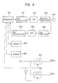
- a tilt sensor 600 is provided. In Fig. 6, portions corresponding to those in Fig. 2 or Fig. 3 are given corresponding reference numerals.
- the tilt sensor 600 detects whether or not the container is tilted. When the tilt is equal to or greater than a predetermined value, the container is set in transmission mode. Otherwise, the container is in reception mode. The amount of tilt is detected by the processor 100, and hysterisis is provided for switching between transmission and reception. Therefore, a carrier used in FSK modulation may be shared (even in cases of plural containers), and the apparatus may be simplified. In contrast, because it is undesirable for the power source for its own transmission circuit to be operating in reception mode, switching is performed by switches 601 and 602. Needless to say, it is also possible to simply switch the FSK modulator 101 and the FSK demodulator 304 without controlling the power source for the transmission/reception circuitry. In this embodiment, for purposes of power saving as well, the power source itself is switched. In the drawing, RXVcc is a power supply line to the reception side circuit, and TXVcc is a power supply line to the transmission side circuit.
- FIG. 7 shows this embodiment in its entirety. In this drawing, portions corresponding to those in Fig. 2, 3, or 6 are given corresponding reference numerals.
- frequencies f1 and f2 for example, 10 MHz and 14 MHz
- f3 and f4 for example, 18 MHz and 22 MHz
- transmission/reception are distinguished from other containers by the frequency bands as shown below:
- a liquid supply apparatus 900 includes means for performing information communications which uses a liquid as a medium, and means for supplying the liquid.
- the liquid supply apparatus 900 includes a faucet-cum-electrode 901.
- a container 902 is a container comprising communications means similar to that of the receiver side container 21 shown in Fig. 3.
- the liquid is supplied from the liquid supply apparatus 900 to a container.
- data is simultaneously supplied to the container 902.
- the price of the liquid supplied through the faucet-cum-electrode 901 is charged to the container 902. Therefore, when the container is returned, the account can be settled automatically via a network.
- the calculation means and memory means are included in the container, when poured a plurality of times, the total price can be stored by the container.
- FIG. 10 shows this embodiment.
- signal transmission means 1005 including an FM modulator, a buffer amplifier and the like, and video playback means 1006 for supplying a video signal thereto are connected to a container 1001.
- video playback means 1006 for example, a portable DV videocassette player/recorder, a video camera, or a video recording/reproducing apparatus using a hard disk may be used.
- 1001, 1005, and 1006 may be integrated, or connected by wires.
- a transmission path may be formed via the human body.
- a container 1002 is a signal receiver side container, and a demodulator 1003 (including a pre-amplifier, a filter, and the like) is connected.
- a video signal monitor 1004 is connected to the output.
- a video signal memory may be prepared on the memory 1004 side, and in the absence of a video signal, this memory may be read.
- using audio signals or video-audio signals at the same time are also possible (in this case, modulation band splitting is performed).
Landscapes
- Engineering & Computer Science (AREA)
- Computer Networks & Wireless Communication (AREA)
- Signal Processing (AREA)
- Arrangements For Transmission Of Measured Signals (AREA)
- Details Of Rigid Or Semi-Rigid Containers (AREA)
Abstract
Description
| Container | Transmission Frequency | Reception Frequency |
| Container A | f1 and f2 | f3 and f4 |
| Container B | f3 and f4 | f1 and f2 |
Claims (9)
- A signal transmitting apparatus, comprising: a modulator for modulating an electrical signal; a first electrode connected to said modulator; means for bringing said first electrode into direct or electrostatic contact with an electrically conductive liquid; a second electrode for making direct or electrostatic contact using said liquid as a medium; and demodulation means connected to said second electrode, characterized in that the signal is propagated through the liquid.
- A signal transmitting apparatus, comprising: a modulator/demodulator for modulating and demodulating an electrical signal; a first electrode connected to said modulator/demodulator; means for bringing said first electrode into direct or electrostatic contact with an electrically conductive liquid; a second electrode for making direct or electrostatic contact using said liquid as a medium; and modulation/demodulation means connected to said second electrode, characterized in that the signal is propagated through the liquid, and in that communications is two-way.
- The signal transmitting apparatus according to claim 1, wherein a plurality of receiving sides are present, and simultaneous reception of a plurality of signals is made possible.
- The signal transmitting apparatus according to claim 1, characterized in that a plurality of transmitting sides are present, the transmitting sides perform time-division transmission, and a receiving side is made capable of simultaneously receiving a plurality of signals.
- A liquid container characterized by comprising signal generating means; a modulator for modulating an electrical signal from said signal generating means; an electrode connected to said modulator; and a container body for supporting said electrode.
- A liquid container characterized by comprising a container body; an electrode supported by the container body; a demodulator for demodulating a modulated signal supplied to the electrode; and means for processing the demodulated electrical signal.
- A liquid container characterized by comprising signal generating means; a modulator for modulating an electrical signal from said signal generating means; an electrode connected to said modulator; a container body for supporting said electrode; a demodulator for demodulating a modulated signal externally supplied to said electrode; and means for processing the demodulated electrical signal.
- A signal transmitting method for exchanging a liquid between a first liquid container comprising signal generating means, a modulator for modulating an electrical signal from said signal generating means, a first electrode connected to said modulator, and a first container body for supporting said first electrode, and a second liquid container comprising a second container body, a second electrode supported by said second container body, a demodulator for demodulating the modulated signal supplied to the second electrode, and means for processing the demodulated electrical signal, whereby a signal is transmitted from said first liquid container to said second liquid container.
- The signal transmitting method according to claim 8, wherein said first liquid container further comprises a demodulator for demodulating a modulated signal externally supplied to said first electrode and means for processing the demodulated electrical signal, and said second liquid container further comprises signal generating means and a modulator for modulating and supplying to said second electrode an electrode signal from said signal generating means, whereby a signal is transmitted from said second liquid container to said first liquid container.
Applications Claiming Priority (3)
| Application Number | Priority Date | Filing Date | Title |
|---|---|---|---|
| JP2001054308A JP2002261701A (en) | 2001-02-28 | 2001-02-28 | Signal transmission apparatus and method |
| JP2001054308 | 2001-02-28 | ||
| PCT/JP2002/001282 WO2002069530A1 (en) | 2001-02-28 | 2002-02-15 | Signal transmission device and method |
Publications (2)
| Publication Number | Publication Date |
|---|---|
| EP1274187A1 true EP1274187A1 (en) | 2003-01-08 |
| EP1274187A4 EP1274187A4 (en) | 2005-01-26 |
Family
ID=18914660
Family Applications (1)
| Application Number | Title | Priority Date | Filing Date |
|---|---|---|---|
| EP02712374A Withdrawn EP1274187A4 (en) | 2001-02-28 | 2002-02-15 | DEVICE AND METHOD FOR SIGNAL TRANSMISSION |
Country Status (6)
| Country | Link |
|---|---|
| US (1) | US6989755B2 (en) |
| EP (1) | EP1274187A4 (en) |
| JP (1) | JP2002261701A (en) |
| KR (1) | KR20030007534A (en) |
| CN (1) | CN1457567A (en) |
| WO (1) | WO2002069530A1 (en) |
Cited By (1)
| Publication number | Priority date | Publication date | Assignee | Title |
|---|---|---|---|---|
| EP2284743A3 (en) * | 2003-03-28 | 2013-08-14 | CareFusion 303, Inc. | Infusion data communication system |
Families Citing this family (4)
| Publication number | Priority date | Publication date | Assignee | Title |
|---|---|---|---|---|
| US8798979B2 (en) | 2005-05-11 | 2014-08-05 | Carefusion 303, Inc. | Infusion device data set analyzer |
| WO2008008281A2 (en) * | 2006-07-07 | 2008-01-17 | Proteus Biomedical, Inc. | Smart parenteral administration system |
| WO2009055733A1 (en) * | 2007-10-25 | 2009-04-30 | Proteus Biomedical, Inc. | Fluid transfer port information system |
| US20100071572A1 (en) * | 2008-09-23 | 2010-03-25 | Carroll Robert B | Waste compactor and container monitoring system |
Family Cites Families (14)
| Publication number | Priority date | Publication date | Assignee | Title |
|---|---|---|---|---|
| US3964051A (en) * | 1973-02-12 | 1976-06-15 | Infodyne, Inc. | Electrostatic communication system |
| US4187489A (en) * | 1978-04-27 | 1980-02-05 | Silberg Paul A | Method and apparatus for propagating electrical signals through a conducting dielectric fluid |
| GB2163029B (en) | 1984-08-06 | 1987-11-18 | Peter James Raynor | Inductive communication system |
| EP0229631B1 (en) * | 1986-01-13 | 1993-09-08 | Abbott Laboratories | Electronic data storage and retrieval apparatus and method |
| DE3639695A1 (en) * | 1986-11-20 | 1988-06-01 | Guy Heusquin | DEVICE FOR DISPLAYING VALUES OF INTEREST IN A HYDRO CULTURE |
| JPH06308252A (en) * | 1993-04-24 | 1994-11-04 | Sumitomo Electric Ind Ltd | Conductive liquid detecting device |
| US5386196A (en) * | 1993-08-23 | 1995-01-31 | Denmar, Inc. | System and method for accurate contactless measurement of the resistivity of a test material |
| JPH07212268A (en) * | 1994-01-12 | 1995-08-11 | Nippon Telegr & Teleph Corp <Ntt> | Water depth display transceiver |
| JPH07235895A (en) * | 1994-02-23 | 1995-09-05 | Nec Eng Ltd | Multi-frequency compatible transponder |
| JP3156117B2 (en) * | 1994-08-22 | 2001-04-16 | 雄一 工藤 | Underwater telemetry device |
| IT1280883B1 (en) * | 1995-08-01 | 1998-02-11 | Arrigo Castelli | ELECTRODE FOR THE ACQUISITION OF A BIOLOGICAL SIGNAL OF AN ELECTRICAL NATURE, IN PARTICULAR AN ELECTROCARDIOGRAPHIC SIGNAL. |
| US5675259A (en) * | 1995-09-14 | 1997-10-07 | The United States Of America As Represented By The Administrator Of The National Aeronautics And Space Administration | Method and apparatus for measuring fluid flow |
| GB9713573D0 (en) * | 1997-06-26 | 1997-09-03 | Radiodetection Ltd | Detecting underground pipes |
| US5880364A (en) * | 1997-10-31 | 1999-03-09 | Cosense, Inc. | Non-contact ultrasonic micromeasurement system |
-
2001
- 2001-02-28 JP JP2001054308A patent/JP2002261701A/en active Pending
-
2002
- 2002-02-15 CN CN02800459A patent/CN1457567A/en active Pending
- 2002-02-15 US US10/258,671 patent/US6989755B2/en not_active Expired - Fee Related
- 2002-02-15 WO PCT/JP2002/001282 patent/WO2002069530A1/en not_active Ceased
- 2002-02-15 KR KR1020027014038A patent/KR20030007534A/en not_active Ceased
- 2002-02-15 EP EP02712374A patent/EP1274187A4/en not_active Withdrawn
Cited By (2)
| Publication number | Priority date | Publication date | Assignee | Title |
|---|---|---|---|---|
| EP2284743A3 (en) * | 2003-03-28 | 2013-08-14 | CareFusion 303, Inc. | Infusion data communication system |
| US8777894B2 (en) | 2003-03-28 | 2014-07-15 | Carefusion 303, Inc. | Infusion data communication system |
Also Published As
| Publication number | Publication date |
|---|---|
| JP2002261701A (en) | 2002-09-13 |
| US20040222843A1 (en) | 2004-11-11 |
| EP1274187A4 (en) | 2005-01-26 |
| KR20030007534A (en) | 2003-01-23 |
| WO2002069530A1 (en) | 2002-09-06 |
| CN1457567A (en) | 2003-11-19 |
| US6989755B2 (en) | 2006-01-24 |
Similar Documents
| Publication | Publication Date | Title |
|---|---|---|
| EP1901203B1 (en) | Communication apparatus | |
| US8280302B2 (en) | Communication device and method, and program | |
| US4963887A (en) | Full duplex transponder system | |
| EP2071734A2 (en) | Communication apparatus | |
| US20090256684A1 (en) | Communications system and memory card | |
| JPH10222632A (en) | Device and method for reproducing clock signal used for portable data carrier | |
| US6989755B2 (en) | Signal transmission device and method | |
| US5768690A (en) | Radio communication device with improved antenna duplexing apparatus | |
| US20080123599A1 (en) | Communication System, Communication Device And Method, And Program | |
| JPH03209589A (en) | Transmitting / receiving system | |
| JP2002353852A (en) | Wireless communication device and wireless communication system | |
| US10476555B2 (en) | Chassis based antenna for a near field communication (NFC) enabled device | |
| EP0533062B1 (en) | Antenna for transceiver devices or the like | |
| US20080259827A1 (en) | Communication System Using Frequency According to Security or Transmission Distance | |
| US20070129021A1 (en) | Nrd guide transceiver, download system using the same, and download memory used for the same | |
| US12028128B2 (en) | Near-field communication device | |
| MXPA04000572A (en) | Method for testing an appliance comprising an audio port, and a respective appliance. | |
| JP2002064398A (en) | Wireless transmission equipment | |
| JPH0690194A (en) | Simultaneous data transmitting-receiving system using microwaves | |
| JP2631664B2 (en) | Non-contact magnetic coupling transmission / reception method | |
| US8489027B2 (en) | Method and apparatus for communicating sound wave of human body | |
| JP2004048221A (en) | Transmitter-receiver for communication between living bodies | |
| JP2008059524A (en) | RFID reader / writer device, RFID reader / writer control method, and RFID reader / writer control program | |
| JPH0265415A (en) | battery voltage display device | |
| JPH0444188A (en) | Transmission and reception system |
Legal Events
| Date | Code | Title | Description |
|---|---|---|---|
| PUAI | Public reference made under article 153(3) epc to a published international application that has entered the european phase |
Free format text: ORIGINAL CODE: 0009012 |
|
| 17P | Request for examination filed |
Effective date: 20021028 |
|
| AK | Designated contracting states |
Kind code of ref document: A1 Designated state(s): AT BE CH CY DE DK ES FI FR GB GR IE IT LI LU MC NL PT SE TR |
|
| RIN1 | Information on inventor provided before grant (corrected) |
Inventor name: SCIAMMARELLA, E.A.,C/O SONY CORPORATION Inventor name: TAJIMA, SHIGERU,SONY COMPUTER SCIENCE LAB. INC. Inventor name: KARASAWA, HIDENORI,SONY COMPUTER SCIENCE LAB. INC Inventor name: AYATSUKA, YUJI,SONY COMPUTER SCIENCE LAB. INC Inventor name: HASEGAWA, TOTAC/O SONY CORPORATION Inventor name: REKIMOTO, JUNICHI,SONY COMPUTER SCIENCE LAB. INC Inventor name: MATSUSHITA, N.,SONY COMPUTER SCIENCE LAB. INC. |
|
| A4 | Supplementary search report drawn up and despatched |
Effective date: 20041215 |
|
| 17Q | First examination report despatched |
Effective date: 20071012 |
|
| STAA | Information on the status of an ep patent application or granted ep patent |
Free format text: STATUS: THE APPLICATION IS DEEMED TO BE WITHDRAWN |
|
| 18D | Application deemed to be withdrawn |
Effective date: 20080223 |