EP1274147A2 - Polymer electrolyte membrane and fuel cell - Google Patents
Polymer electrolyte membrane and fuel cell Download PDFInfo
- Publication number
- EP1274147A2 EP1274147A2 EP02014560A EP02014560A EP1274147A2 EP 1274147 A2 EP1274147 A2 EP 1274147A2 EP 02014560 A EP02014560 A EP 02014560A EP 02014560 A EP02014560 A EP 02014560A EP 1274147 A2 EP1274147 A2 EP 1274147A2
- Authority
- EP
- European Patent Office
- Prior art keywords
- polymer electrolyte
- block
- electrolyte membrane
- sulfonic acid
- acid groups
- Prior art date
- Legal status (The legal status is an assumption and is not a legal conclusion. Google has not performed a legal analysis and makes no representation as to the accuracy of the status listed.)
- Granted
Links
Classifications
-
- B—PERFORMING OPERATIONS; TRANSPORTING
- B01—PHYSICAL OR CHEMICAL PROCESSES OR APPARATUS IN GENERAL
- B01D—SEPARATION
- B01D67/00—Processes specially adapted for manufacturing semi-permeable membranes for separation processes or apparatus
- B01D67/0081—After-treatment of organic or inorganic membranes
- B01D67/0088—Physical treatment with compounds, e.g. swelling, coating or impregnation
-
- H—ELECTRICITY
- H01—ELECTRIC ELEMENTS
- H01M—PROCESSES OR MEANS, e.g. BATTERIES, FOR THE DIRECT CONVERSION OF CHEMICAL ENERGY INTO ELECTRICAL ENERGY
- H01M8/00—Fuel cells; Manufacture thereof
- H01M8/02—Details
-
- B—PERFORMING OPERATIONS; TRANSPORTING
- B01—PHYSICAL OR CHEMICAL PROCESSES OR APPARATUS IN GENERAL
- B01D—SEPARATION
- B01D69/00—Semi-permeable membranes for separation processes or apparatus characterised by their form, structure or properties; Manufacturing processes specially adapted therefor
- B01D69/12—Composite membranes; Ultra-thin membranes
-
- B—PERFORMING OPERATIONS; TRANSPORTING
- B01—PHYSICAL OR CHEMICAL PROCESSES OR APPARATUS IN GENERAL
- B01D—SEPARATION
- B01D69/00—Semi-permeable membranes for separation processes or apparatus characterised by their form, structure or properties; Manufacturing processes specially adapted therefor
- B01D69/14—Dynamic membranes
- B01D69/141—Heterogeneous membranes, e.g. containing dispersed material; Mixed matrix membranes
-
- B—PERFORMING OPERATIONS; TRANSPORTING
- B01—PHYSICAL OR CHEMICAL PROCESSES OR APPARATUS IN GENERAL
- B01D—SEPARATION
- B01D71/00—Semi-permeable membranes for separation processes or apparatus characterised by the material; Manufacturing processes specially adapted therefor
- B01D71/06—Organic material
- B01D71/52—Polyethers
- B01D71/522—Aromatic polyethers
- B01D71/5222—Polyetherketone, polyetheretherketone, or polyaryletherketone
-
- B—PERFORMING OPERATIONS; TRANSPORTING
- B01—PHYSICAL OR CHEMICAL PROCESSES OR APPARATUS IN GENERAL
- B01D—SEPARATION
- B01D71/00—Semi-permeable membranes for separation processes or apparatus characterised by the material; Manufacturing processes specially adapted therefor
- B01D71/06—Organic material
- B01D71/76—Macromolecular material not specifically provided for in a single one of groups B01D71/08 - B01D71/74
- B01D71/80—Block polymers
-
- B—PERFORMING OPERATIONS; TRANSPORTING
- B01—PHYSICAL OR CHEMICAL PROCESSES OR APPARATUS IN GENERAL
- B01D—SEPARATION
- B01D71/00—Semi-permeable membranes for separation processes or apparatus characterised by the material; Manufacturing processes specially adapted therefor
- B01D71/06—Organic material
- B01D71/76—Macromolecular material not specifically provided for in a single one of groups B01D71/08 - B01D71/74
- B01D71/82—Macromolecular material not specifically provided for in a single one of groups B01D71/08 - B01D71/74 characterised by the presence of specified groups, e.g. introduced by chemical after-treatment
-
- C—CHEMISTRY; METALLURGY
- C08—ORGANIC MACROMOLECULAR COMPOUNDS; THEIR PREPARATION OR CHEMICAL WORKING-UP; COMPOSITIONS BASED THEREON
- C08J—WORKING-UP; GENERAL PROCESSES OF COMPOUNDING; AFTER-TREATMENT NOT COVERED BY SUBCLASSES C08B, C08C, C08F, C08G or C08H
- C08J5/00—Manufacture of articles or shaped materials containing macromolecular substances
- C08J5/20—Manufacture of shaped structures of ion-exchange resins
- C08J5/22—Films, membranes or diaphragms
- C08J5/2206—Films, membranes or diaphragms based on organic and/or inorganic macromolecular compounds
- C08J5/2218—Synthetic macromolecular compounds
- C08J5/2256—Synthetic macromolecular compounds based on macromolecular compounds obtained by reactions other than those involving carbon-to-carbon bonds, e.g. obtained by polycondensation
-
- C—CHEMISTRY; METALLURGY
- C08—ORGANIC MACROMOLECULAR COMPOUNDS; THEIR PREPARATION OR CHEMICAL WORKING-UP; COMPOSITIONS BASED THEREON
- C08J—WORKING-UP; GENERAL PROCESSES OF COMPOUNDING; AFTER-TREATMENT NOT COVERED BY SUBCLASSES C08B, C08C, C08F, C08G or C08H
- C08J5/00—Manufacture of articles or shaped materials containing macromolecular substances
- C08J5/20—Manufacture of shaped structures of ion-exchange resins
- C08J5/22—Films, membranes or diaphragms
- C08J5/2206—Films, membranes or diaphragms based on organic and/or inorganic macromolecular compounds
- C08J5/2218—Synthetic macromolecular compounds
- C08J5/2268—Synthetic macromolecular compounds based on macromolecular compounds obtained by reactions involving unsaturated carbon-to-carbon bonds, and by reactions not involving this type of bond
-
- H—ELECTRICITY
- H01—ELECTRIC ELEMENTS
- H01B—CABLES; CONDUCTORS; INSULATORS; SELECTION OF MATERIALS FOR THEIR CONDUCTIVE, INSULATING OR DIELECTRIC PROPERTIES
- H01B1/00—Conductors or conductive bodies characterised by the conductive materials; Selection of materials as conductors
- H01B1/06—Conductors or conductive bodies characterised by the conductive materials; Selection of materials as conductors mainly consisting of other non-metallic substances
- H01B1/12—Conductors or conductive bodies characterised by the conductive materials; Selection of materials as conductors mainly consisting of other non-metallic substances organic substances
- H01B1/122—Ionic conductors
-
- H—ELECTRICITY
- H01—ELECTRIC ELEMENTS
- H01M—PROCESSES OR MEANS, e.g. BATTERIES, FOR THE DIRECT CONVERSION OF CHEMICAL ENERGY INTO ELECTRICAL ENERGY
- H01M8/00—Fuel cells; Manufacture thereof
- H01M8/10—Fuel cells with solid electrolytes
- H01M8/1016—Fuel cells with solid electrolytes characterised by the electrolyte material
- H01M8/1018—Polymeric electrolyte materials
- H01M8/102—Polymeric electrolyte materials characterised by the chemical structure of the main chain of the ion-conducting polymer
- H01M8/1023—Polymeric electrolyte materials characterised by the chemical structure of the main chain of the ion-conducting polymer having only carbon, e.g. polyarylenes, polystyrenes or polybutadiene-styrenes
-
- H—ELECTRICITY
- H01—ELECTRIC ELEMENTS
- H01M—PROCESSES OR MEANS, e.g. BATTERIES, FOR THE DIRECT CONVERSION OF CHEMICAL ENERGY INTO ELECTRICAL ENERGY
- H01M8/00—Fuel cells; Manufacture thereof
- H01M8/10—Fuel cells with solid electrolytes
- H01M8/1016—Fuel cells with solid electrolytes characterised by the electrolyte material
- H01M8/1018—Polymeric electrolyte materials
- H01M8/102—Polymeric electrolyte materials characterised by the chemical structure of the main chain of the ion-conducting polymer
- H01M8/1025—Polymeric electrolyte materials characterised by the chemical structure of the main chain of the ion-conducting polymer having only carbon and oxygen, e.g. polyethers, sulfonated polyetheretherketones [S-PEEK], sulfonated polysaccharides, sulfonated celluloses or sulfonated polyesters
-
- H—ELECTRICITY
- H01—ELECTRIC ELEMENTS
- H01M—PROCESSES OR MEANS, e.g. BATTERIES, FOR THE DIRECT CONVERSION OF CHEMICAL ENERGY INTO ELECTRICAL ENERGY
- H01M8/00—Fuel cells; Manufacture thereof
- H01M8/10—Fuel cells with solid electrolytes
- H01M8/1016—Fuel cells with solid electrolytes characterised by the electrolyte material
- H01M8/1018—Polymeric electrolyte materials
- H01M8/102—Polymeric electrolyte materials characterised by the chemical structure of the main chain of the ion-conducting polymer
- H01M8/1027—Polymeric electrolyte materials characterised by the chemical structure of the main chain of the ion-conducting polymer having carbon, oxygen and other atoms, e.g. sulfonated polyethersulfones [S-PES]
-
- H—ELECTRICITY
- H01—ELECTRIC ELEMENTS
- H01M—PROCESSES OR MEANS, e.g. BATTERIES, FOR THE DIRECT CONVERSION OF CHEMICAL ENERGY INTO ELECTRICAL ENERGY
- H01M8/00—Fuel cells; Manufacture thereof
- H01M8/10—Fuel cells with solid electrolytes
- H01M8/1016—Fuel cells with solid electrolytes characterised by the electrolyte material
- H01M8/1018—Polymeric electrolyte materials
- H01M8/102—Polymeric electrolyte materials characterised by the chemical structure of the main chain of the ion-conducting polymer
- H01M8/103—Polymeric electrolyte materials characterised by the chemical structure of the main chain of the ion-conducting polymer having nitrogen, e.g. sulfonated polybenzimidazoles [S-PBI], polybenzimidazoles with phosphoric acid, sulfonated polyamides [S-PA] or sulfonated polyphosphazenes [S-PPh]
-
- H—ELECTRICITY
- H01—ELECTRIC ELEMENTS
- H01M—PROCESSES OR MEANS, e.g. BATTERIES, FOR THE DIRECT CONVERSION OF CHEMICAL ENERGY INTO ELECTRICAL ENERGY
- H01M8/00—Fuel cells; Manufacture thereof
- H01M8/10—Fuel cells with solid electrolytes
- H01M8/1016—Fuel cells with solid electrolytes characterised by the electrolyte material
- H01M8/1018—Polymeric electrolyte materials
- H01M8/102—Polymeric electrolyte materials characterised by the chemical structure of the main chain of the ion-conducting polymer
- H01M8/1032—Polymeric electrolyte materials characterised by the chemical structure of the main chain of the ion-conducting polymer having sulfur, e.g. sulfonated-polyethersulfones [S-PES]
-
- H—ELECTRICITY
- H01—ELECTRIC ELEMENTS
- H01M—PROCESSES OR MEANS, e.g. BATTERIES, FOR THE DIRECT CONVERSION OF CHEMICAL ENERGY INTO ELECTRICAL ENERGY
- H01M8/00—Fuel cells; Manufacture thereof
- H01M8/10—Fuel cells with solid electrolytes
- H01M8/1016—Fuel cells with solid electrolytes characterised by the electrolyte material
- H01M8/1018—Polymeric electrolyte materials
- H01M8/1058—Polymeric electrolyte materials characterised by a porous support having no ion-conducting properties
- H01M8/106—Polymeric electrolyte materials characterised by a porous support having no ion-conducting properties characterised by the chemical composition of the porous support
-
- B—PERFORMING OPERATIONS; TRANSPORTING
- B01—PHYSICAL OR CHEMICAL PROCESSES OR APPARATUS IN GENERAL
- B01D—SEPARATION
- B01D71/00—Semi-permeable membranes for separation processes or apparatus characterised by the material; Manufacturing processes specially adapted therefor
- B01D71/06—Organic material
- B01D71/52—Polyethers
-
- B—PERFORMING OPERATIONS; TRANSPORTING
- B01—PHYSICAL OR CHEMICAL PROCESSES OR APPARATUS IN GENERAL
- B01D—SEPARATION
- B01D71/00—Semi-permeable membranes for separation processes or apparatus characterised by the material; Manufacturing processes specially adapted therefor
- B01D71/06—Organic material
- B01D71/58—Other polymers having nitrogen in the main chain, with or without oxygen or carbon only
- B01D71/60—Polyamines
-
- B—PERFORMING OPERATIONS; TRANSPORTING
- B01—PHYSICAL OR CHEMICAL PROCESSES OR APPARATUS IN GENERAL
- B01D—SEPARATION
- B01D71/00—Semi-permeable membranes for separation processes or apparatus characterised by the material; Manufacturing processes specially adapted therefor
- B01D71/06—Organic material
- B01D71/66—Polymers having sulfur in the main chain, with or without nitrogen, oxygen or carbon only
- B01D71/68—Polysulfones; Polyethersulfones
-
- C—CHEMISTRY; METALLURGY
- C08—ORGANIC MACROMOLECULAR COMPOUNDS; THEIR PREPARATION OR CHEMICAL WORKING-UP; COMPOSITIONS BASED THEREON
- C08J—WORKING-UP; GENERAL PROCESSES OF COMPOUNDING; AFTER-TREATMENT NOT COVERED BY SUBCLASSES C08B, C08C, C08F, C08G or C08H
- C08J2365/00—Characterised by the use of macromolecular compounds obtained by reactions forming a carbon-to-carbon link in the main chain; Derivatives of such polymers
- C08J2365/02—Polyphenylenes
-
- C—CHEMISTRY; METALLURGY
- C08—ORGANIC MACROMOLECULAR COMPOUNDS; THEIR PREPARATION OR CHEMICAL WORKING-UP; COMPOSITIONS BASED THEREON
- C08J—WORKING-UP; GENERAL PROCESSES OF COMPOUNDING; AFTER-TREATMENT NOT COVERED BY SUBCLASSES C08B, C08C, C08F, C08G or C08H
- C08J2371/00—Characterised by the use of polyethers obtained by reactions forming an ether link in the main chain; Derivatives of such polymers
- C08J2371/08—Polyethers derived from hydroxy compounds or from their metallic derivatives
- C08J2371/10—Polyethers derived from hydroxy compounds or from their metallic derivatives from phenols
- C08J2371/12—Polyphenylene oxides
-
- H—ELECTRICITY
- H01—ELECTRIC ELEMENTS
- H01M—PROCESSES OR MEANS, e.g. BATTERIES, FOR THE DIRECT CONVERSION OF CHEMICAL ENERGY INTO ELECTRICAL ENERGY
- H01M2300/00—Electrolytes
- H01M2300/0017—Non-aqueous electrolytes
- H01M2300/0065—Solid electrolytes
- H01M2300/0082—Organic polymers
-
- Y—GENERAL TAGGING OF NEW TECHNOLOGICAL DEVELOPMENTS; GENERAL TAGGING OF CROSS-SECTIONAL TECHNOLOGIES SPANNING OVER SEVERAL SECTIONS OF THE IPC; TECHNICAL SUBJECTS COVERED BY FORMER USPC CROSS-REFERENCE ART COLLECTIONS [XRACs] AND DIGESTS
- Y02—TECHNOLOGIES OR APPLICATIONS FOR MITIGATION OR ADAPTATION AGAINST CLIMATE CHANGE
- Y02E—REDUCTION OF GREENHOUSE GAS [GHG] EMISSIONS, RELATED TO ENERGY GENERATION, TRANSMISSION OR DISTRIBUTION
- Y02E60/00—Enabling technologies; Technologies with a potential or indirect contribution to GHG emissions mitigation
- Y02E60/30—Hydrogen technology
- Y02E60/50—Fuel cells
Definitions
- the present invention relates to a polymer electrolyte membrane, in particular, a polymer electrolyte membrane suitably used for fuel cells, and a method for producing it.
- a solid polymer electrolyte fuel cell using a polymer membrane having proton conductivity as an electrolyte has a compact structure, and provides high output, and it can be operated conveniently, it attracts attention as power supply for moving e.g. vehicles.
- a polymer electrolyte having proton conductivity used for a solid polymer electrolyte fuel cell perfluorosulfonic acid derived materials including Nafion® have mainly been conventionally used because they have excellent characteristics as a fuel cell.
- this material is very expensive, when a power generation system using fuel cells will become wide spread from now on, its cost may become big problems.
- polymers in which sulfonic acid groups are introduced into aromatic polyethers are one of the most promising materials, because such polymers have outstanding heat-resisting property and high film strength.
- a polymer electrolyte composed of random copolymers of sulfonated polyether ketones is disclosed in JP-B-11-502249, and a polymer electrolyte composed of random copolymer of sulfonated polyether sulfone is disclosed in JP-A-10-45913 and 10-21943.
- a cation exchange membrane in which a cation exchange resin is filled into pores of a porous membrane made of ultrahigh-molecular weight polyolefin is disclosed as a polymer electrolyte membrane for solid polymer electrolyte type fuel cells in JP-A-1-22932.
- a cation exchange membrane in which a fluorinated resin represented by polytetrafluoroethylene is used as a base material is disclosed in JP-A-6-29032 and 9-194609.
- a method of improving penetrating power of a solvent used to dissolve a polymer electrolyte, and of obtaining composite membrane by giving surface treatment to a porous membrane is also disclosed.
- a method to conduct hydrophilizing processing by plasma etching of a porous fluorinated resin film JP-B-62-252074
- a method for treating a surface of a porous membrane with surface active agents JP-A-04-204522
- a method of hydrophilizing a porous membrane with a polymer different from the polymer electrolyte used for the membrane JP-A- 6-271688) are proposed.
- An object of the present invention is to provide a polymer electrolyte membrane having outstanding water resistance and high thermal resistance, moreover having a practical strength required for use as a polymer electrolyte membrane of a solid polymer electrolyte type fuel cell at low price. Furthermore, another object of the present invention is to provide a method for producing a polymer electrolyte composite membrane having good appearance and moreover maintaining original physical properties as porous membrane, without using surface active agent and other polymers.
- a composite membrane of a specific polymer electrolyte with a porous membrane demonstrates a practical strength for use as a polymer electrolyte membrane for solid polymer electrolyte type fuel cells, and by providing a method for producing a polymer electrolyte composite membrane having a good appearance and moreover maintaining original physical properties as porous membrane by selecting a solvent having a contact angle to a porous membrane in a specific range as a solvent used for dissolving the polymer electrolyte.
- the present invention provides a polymer electrolyte membrane comprising a porous membrane, and a polymer electrolyte which comprises a block copolymer comprising one or more of blocks in which sulfonic acid groups are introduced and one or more blocks in which sulfonic acid groups are not substantially introduced wherein at least one block in said block copolymer is a block having aromatic rings in the polymer chain of said block polymer; and a fuel cell using the membrane.
- the present invention provides a method for producing a polymer electrolyte membrane comprising the steps of,
- a block copolymer is a polymer in which two or more of blocks having different repeating units are bonded directly, or bonded through linkage group, and a block includes two or more repeating units.
- at least one block is a block having an aromatic ring in the polymer chain.
- a block in which sulfonic acid groups are introduced is a block in which not less than 0.5 sulfonic acid groups (group expressed with -SO 3 H) per one repeating unit on average are bonded to any part of repeating units constituting the block.
- a block having an aromatic ring, and a block having a structure with sulfonic acid group bonded directly to the aromatic ring is preferable because it may be easily synthesized.
- a block into which sulfonic acid groups are not substantially introduced is a block in which no more than 0.1 sulfonic acid groups per one repeating unit constituting the block on average is introduced.
- a block with aromatic rings introduced in the polymer chain may be a block in which the above described sulfonic acid groups are introduced, or may be a block in which sulfonic acid groups are not substantially introduced, and may be both of the blocks.
- sulfonic acid groups for example, polystyrene, poly( ⁇ -methyl styrene), poly(allylphenyl ether), poly(phenyl glycidylether), poly(phenylene ether), poly(phenylene sulfide), poly (ether ether ketone), poly (ether ether sulfone), polysulfone, poly(phenylmethylsiloxane), poly(diphenylsiloxane), poly(phenylmethylphosphazene), poly(diphenylphosphazene), or a block in which sulfonic acid group is introduced into a block comprising a repeating unit having epoxy group are included.
- a block having a repeating unit represented by general formula [1] a block having a repeating unit represented by general formula [2], or a block in which sulfonic acid groups are introduced into a block having epoxy group is preferably used.
- X represents -O-, -S-, -NH-, or direct bond
- R 1 represents an alkyl group with carbon numbers of from 1 to 6, alkoxy group with carbon numbers of from 1 to 6, or phenyl group
- a is integer of from 0 to 3.
- R 1 represents a group selected from following structures in Formula [2].
- R 2 represents an alkyl group with carbon numbers of from 1 to 6, alkoxy group with carbon numbers of from 1 to 6, phenyl group, or phenoxy group
- b is an integer of 0 to 4
- c is an integer of 0 to 6.
- poly(phenylene), poly(aniline), poly(phenylene ether) and poly(phenylene sulfide) may be mentioned.
- poly(1,4-phenylene ether), poly(2-phenyl-1,4-phenylene ether), and poly(2,6-diphenyl-1,4-phenylene ether) are more preferable, and poly(2-phenyl-1,4-phenylene ether) is still more preferable.
- Precursors of a block having repeating units represented by the general formula [1] may be manufactured by well-known methods.
- a poly(phenylene ether) may be manufactured by an oxidation polymerization method in which phenol is oxidized in the presence of a catalyst, and by a method in which halogenated phenol is condensed in the presence of catalysts and alkalis (called Ullmann reaction).
- a precursor of a block means a polymer having reactive part giving a block copolymer by copolymerization reaction with other polymer having reacting part. (same hereinafter)
- a precursor of a block having repeating units represented by the above described general formula [2] may be obtained by ring opening polymerization of a glycidyl ether having an aromatic ring represented by following formula.
- epoxy compounds that do not include aromatic ring for example, ethylene oxide, propylene oxide, 1,2-epoxy butane, cyclohexane epoxide, epifluorohydrin, epichlorohydrin, epibromohydrin, trifluoro propylene oxide, methyl glycidyl ether, ethyl glycidyl ether, propyl glycidyl ether and butyl glycidyl ether may be mentioned.
- a glycidyl ether component having an aromatic ring is preferably no less than 60 % by weight, and more preferably no less than 80 % by weight.
- a number of repeating units represented by the general formula [2] is preferably from 2 to 200, and more preferably is from 5 to 50.
- the above-described block having epoxy groups is obtained from a polymer having one or two or more of epoxy groups as a precursor of a block.
- a block having epoxy groups may include a block in a block copolymer having a epoxy groups as a result.
- a block comprising polymer having epoxy groups with aromatic rings in the polymer chain is more preferable, and it is still more preferable that it is a block having repeating units represented by general formula [3].
- Ar 2 represents a group selected from following structures.
- R 3 represents an alkyl group with carbon numbers of from 1 to 6, alkoxy group with carbon numbers of from 1 to 6, or phenyl group
- d is an integer of from 0 to 3
- e is an integer of from 0 to 2.
- R 3 represents an alkyl group with carbon numbers of from 1 to 6, alkoxy group with carbon numbers of from 1 to 6, or phenyl group
- d is an integer of from 0 to 3
- e is an integer of from 0 to 2.
- Y represents -O-, -S-, an alkylene group with carbon numbers of from 1 to 20, halogenated alkylene group with carbon numbers of from 1 to 10, or alkylene dioxy group with carbon numbers of from 1 to 20.
- Y represents -O-, -S-, an alkylene group with carbon numbers of from 1 to 20, halogenated alkylene group with carbon numbers of from 1 to 10, or alkylene dioxy group with carbon numbers of from 1 to 20
- Polymers having repeating units represented by the general formula [3] are synthesized by well-known methods. As the above described methods, a method in which diol compounds represented by HO-Ar 2 -OH are reacted with epichlorohydrin in the presence of alkali, and a method in which diol compounds and diglycidylether compounds are reacted may be mentioned.
- diol compounds represented by HO-Ar 2 -OH specifically, hydroquinone, resorcinol, catechol, 1,2-dihydroxy naphthalene, 1,4-dihydroxy naphthalene, 1,5-dihydroxy naphthalene, 2,6-dihydroxy naphthalene, 2,7-dihydroxy naphthalene, 4,4'-dihydroxy biphenyl, 2,4'-dihydroxy biphenyl, 2,2'-dihydroxy biphenyl, 4,4'-dihydroxy diphenylmethane, 1,1-bis(4-hydroxy phenyl)ethane, 2,2-bis(4-hydroxy phenyl)propane, 2,2-bis(4-hydroxy phenyl)butane, 1,1-bis(4-hydroxy phenyl)cyclohexane, 2,2-bis(4-hydroxy phenyl)-1,1,1,3,3,3-hexa fluoro propane, 1,1-bis(4-hydroxy pheny
- the number of repeating units composed of blocks obtained from polymers with repeating units represented by the general formula [3] is preferably from 2 to 200, and more preferably from 4 to 50.
- the polymer electrolyte in the present invention comprises a block copolymer which has one or more of the above described blocks in which sulfonic acid groups are introduced, and blocks in which sulfonic acid groups are not substantially introduced.
- a block comprising aromatic polyethers having repeating units represented by general formula [4] is preferable because of its high thermal resistance.
- R 4 represents an alkyl group with carbon numbers of from 1 to 6, and f is an integer of from 0 to 4. When there are two or more R 4 , these may be the same, or may be different from each other.
- Z represents -CO- or -SO 2 -.
- Blocks comprising polyether ketones, blocks comprising polyether sulfones may be illustrated.
- Eapecially polyether sulfones in which Z is -SO 2 - in the general formula [4] are preferable because of their high solubility in solvents.
- Polyether sulfones that are examples of a precursor of blocks shown in the general formula [4] may be synthesized by polycondensation of 4,4'-dihydroxy diphenyl sulfone and 4,4'-dichloro diphenyl sulfone.
- the weight-average molecular weight of the precursor of the block obtained from polyether sulfone is preferably from 2000 to 500000, and more preferably from 8000 to 100000. When the molecular weight is smaller than 2000, film strength and thermal resistance of the copolymer may decrease, and when the molecular weight is larger than 500000, solubility may be small.
- poly(phenylene ether) that is an example of a precursor of a block shown by the general formula [1] as repeating unit, and polyether sulfone that is an example of a precursor of a block shown by the general formula [4] as repeating unit are copolymerized
- a method of condensing poly(phenylene ether) having hydroxyl groups remaining at the end of the polymer chain, and polyether sulfone having halogens remaining at the end of the polymer chain under existence of alkali may be illustrated.
- copolymerization may be conducted by a similar condensation reaction using dihalogenated compounds such as 4,4'-difluoro benzophenone or 4,4'-dichloro diphenyl sulfone as a linking agent for combining poly(phenylene ether) and polyether sulfone to obtain a block copolymer.
- dihalogenated compounds such as 4,4'-difluoro benzophenone or 4,4'-dichloro diphenyl sulfone
- copolymerization may be conducted by converting end hydroxyl groups, which exist at the end of the polymer chain of polyether sulfone, into metal phenolate, by conducting ring opening polymerization of glycidyl ether including aromatic ring at the alkali metal phenolate as a polymerization starting point, and subsequently by conducting sulfonation.
- a precursor of a block is prepared by reacting phenyl glycidyl ether with glycidyl ethers having halogen usable for blocking reaction such as epichlorohydrin, and then the obtained precursor of a block is condensed with polyether sulfones with hydroxyl group remaining at the end of the polymer chain in the presence of alkali,
- block copolymerization is conducted in a molten state without solvent when using polyether sulfone as one of precursors of a block, it is preferable to conduct the reaction in a suitable solvent.
- a suitable solvent aromatic hydrocarbons, ethers, ketones, amides, sulfones, and sulfoxides may be used, amides are preferable because of high solubility of polyether sulfone in amides.
- amides N,N-dimethylformamide, N,N-dimethyIacetamide and N-methyl pyrolidone may be mentioned.
- the reaction temperature of the block copolymerization reaction is preferably 20°C to 250°C, and more preferably it is 50°C to 200°C.
- the amount of blocks in which sulfonic acid groups are not substantially introduced is preferably 60 to 95 % by weight of the block copolymer, and more preferably it is 70 to 90 % by weight.
- the amount of blocks in which sulfonic acid groups are not substantially introduced is more than 95 % by weight, since sulfonic acid equivalent in the block copolymer is small after introduction of sulfonic acid group, sufficient performance as a polymer electrolyte may not be obtained, and when it is less than 60 % by weight, water resistance of the block copolymer after introduction of sulfonic acid group may be insufficient.
- a method of introducing sulfonic acid groups into a specific block is not limited, the following methods may be illustrated; (a) a method in which a precursor of a block with sulfonic acid groups introduced beforehand and a precursor of a block in which sulfonic acid groups are not substantially introduced are copolymerized, (b) a method in which a copolymer comprising a block in which sulfonic acid groups are to be introduced, and a block in which sulfonic acid groups are not to be substantially introduced is produced, and then sulfonic acid is selectively introduced into the block of this copolymer into which sulfonic acid groups are to be introduced.
- the precursor of a block in which sulfonic acid groups are introduced since the sulfonic acid group may prevent copolymerization reaction, the method of above described (b) is preferable.
- a precursor of a block in which sulfonic acid groups are introduced may be prepared by sulfonating a precursor of a block.
- sulfonating agents well-known sulfonating agents, such as sulfuric acid which has no less than 90% of concentration, fuming sulfuric acid, chlorosulfonic acid, and SO 3 may be used.
- a method (c) may be mentioned in which a functional group that exists in a block in which sulfonic acid groups are introduced, and does not exist in a block in which sulfonic acid groups are not substantially introduced is available.
- a method may be proposed in which (d) difference in reactantivity to sulfonation reaction between a block in which sulfonic acid groups are introduced and a block in which sulfo groups are not substantially introduced is utilized.
- the sulfonation reaction is an electrophilic reaction
- sulfonation is conducted by concentrated sulfuric acid using a block copolymer comprising a block having aromatic rings that easily undergo an electrophilic reaction, and a block having aromatic rings that do not easily undergo an eletrophilic reaction
- the former block will be selectively sulfonated.
- a method for producing a polymer electrolyte comprising the steps of reacting the above described precursor of a block having repeating units represented by the general formula [1], [2], or [3] with a precursor of a block having repeating units represented by the general formula [4] to produce a block copolymer, and subsequently sulfonating the copolymer may be mentioned.
- an aromatic ring of a block having repeating units represented by the general formula [4] has a low reactivity as compared with an aromatic ring of a block having repeating units represented by the general formula [1], [2], or [3].
- a block copolymer obtained by reacting a precursor of a block having repeating units represented by the general formula [4] and a precursor of a block having repeating units represented by the general formula [1], [2], or [3] is sulfonated with sulfuric acid under suitable conditions, a block copolymer in which sulfonic acid groups are selectively introduced into blocks having repeating units represented by the general formula [1], [2], or [3], and sulfonic acid groups are not substantially introduced to a block shown by the general formula [4] may be manufactured.
- sulfonating agents such as sulfuric acid with concentration of no less than 90%, fuming sulfuric acid, chlorosulfonic acid and SO 3 may be used.
- sulfuric acid with concentration of no less than 90% is preferable, and sulfuric acid of from 94 to 99 % by weight of concentration is more preferable.
- a small amount of organic solvents that do not participate in sulfonation reaction may be added with sulfuric acid so that sulfonation reaction of the block copolymer proceeds in homogeneous system.
- the resulting sulfonated block copolymer is recovered by pouring the obtained sulfuric acid solution into a large amount of water.
- the concentration of the block copolymer in sulfuric acid is preferably from 1 to 50 % by weight, and more preferably from 5 to 30 % by weight.
- a reaction temperature is preferably from 0°C to 80°C, and more preferably is from 20°C to 40°C.
- the polymer electrolyte of the present invention may include additives used for usual polymer, such as plasticizer, stabilizer, and releasing agent. Besides, intermolecular cross linkage may be introduced into the polymer electrolyte.
- the precursors of a block having repeating units represented by the general formulas [1] to [4] are cheap materials whose synthesis is already established and is performed in large quantities.
- Copolymers obtained by using the precursor as a raw material which is further sulfonated are also very cheap as compared with fluorine derived materials, such as Nafion ®.
- Porous membranes used in the present invention are used for further improvement in strength, plasticity, and durability of polymer electrolyte membranes by being complexed with polymer electrolytes. Therefore, although they may be used in any form made of any material as far as it satisfies the above described purpose of use, from the viewpoint of performing well as a polymer electrolyte membrane of solid polymer electrolyte type fuel cell, the membrane thickness is from 1 to 100 ⁇ m, preferably from 3 to 30 ⁇ m and more preferably from 5 to 20 ⁇ m; pore size is from 0.01 to 10 ⁇ m, preferably from 0.02 to 7 ⁇ m; and a porosity is from 20 to 98%, and preferably from 30 to 95%.
- aliphatic polymers or fluorine polymers are desirable.
- polyethylene, polypropylene and ethylene propylene copolymer may be illustrated.
- Polyethylenes used for the present invention include, for example, copolymers of ethylene and other monomers as well as ethylene homopolymer. Specifically, copolymers of ethylene and ⁇ -olefins referred to as linear low density polyethylene (LLDPE) are included.
- polypropylenes include, for example, propylene block copolymers and random copolymers (these are copolymers with e.g. ethylene and 1-butene).
- thermoplastic resins having at least one carbon-fluorine bond in the molecule may be used without any limitation.
- resins having a structure where all or most of the hydrogens of aliphatic polymers are substituted by fluorine atoms are suitably used.
- Fluorinated resins may be poly(trifluoroethylene), poly(tetrafluoroethylene), poly(chloro trifluoroethylene), poly(tetrafluoroethylene-hexafluoropropylene), poly(tetrafluoroethylene-perfluoro alkylether) and poly(vinylidene fluoride), but the present invention is not limited by them. Among them, in the present invention, poly(tetrafluoroethylene) and poly(tetrafluoroethylene-hexafluoropropylene) are preferable, and poly(tetrafluoroethylene) is more preferable. From viewpoint of excellent mechanical strength, fluorinated resins having an average molecular weight of not less than 100000 are preferable.
- a polymer electrolyte membrane of the present invention is a polymer electrolyte membrane in which the above described polymer electrolyte and the above described porous membrane are combined.
- a method is adopted in which after a solution of a polymer electrolyte dissolved in a solvent is impregnated into a porous membrane, the solvent is removed.
- methods of impregnating a method in which the solution is applied or sprayed to the porous membrane may be adopted, or a method in which the porous membrane is immersed in the solution may be adopted.
- any of methods such as heating, reducing pressure, air-drying, and combination of these may be used as methods of removing solvent.
- a solvent of the polymer electrolyte solution (1) in step (i) will not be limited in particular, if it is a solvent in which a contact angle of the polymer electrolyte solution (1) to the porous membrane gives less than 90° when the electrolyte is dissolved.
- these solvents for example, solvents containing chlorine, such as dichloromethane, chloroform, 1,2-dichloroethane, chlorobenzene, and dichlorobenzene; alcohols, such as methanol, ethanol, and propanol; and mixtures of two or more kinds of these solvents may be used.
- filling of an electrolyte in this step is conducted so that part of the pores of the porous membrane may remain not filled with an electrolyte.
- the amount of filling is usually less than 80% in volume of the pores, preferably less than 60%, and more preferably less than 40%. When too large degree of filling is conducted in this step, filling in the following step will become difficult.
- solvent of solution (2) of polymer electrolyte in step of (ii) when an electrolyte is dissolved, a solvent giving a larger contact angle of a solution (2) of polyelectrolyte to the porous membrane than the contact angle of a solution (1) of polyelectrolyte used in step (i) is used. More preferably, a solvent giving a contact angle of not less than 90° to a porous membrane of solution (2) of polymer electrolyte is preferable.
- a boiling point of the solvent is preferably no less than 110°C, and more preferably no less than 120°C.
- aprotic polar solvents such as N,N-dimethylformamide, N,N-dimethylacetamide, N-methyl-2-pyrrolidone, and dimethyl sulfoxide, may be suitably used.
- step (i) surface energy of the porous membrane partly filled with the polymer electrolyte may be raised, and therefore, a contact angle to the porous membrane of solution (1) and (2) of the polymer electrolyte is beforehand measured in the state where the pores of the porous membrane is not filled with the polymer electrolyte
- the step (ii) is preferably carried out on supporting materials.
- the solvent is volatilized from the opposite side of the surface of the porous membrane which touches the supporting material, and while the solvent is being removed, the supporting material continuously soaks up the polymer electrolyte solution by capillary action.
- a combined membrane comprising the porous membrane and the polymer electrolyte may be obtained in a state where the pores of the porous membrane are nearly completely filled with the polymer electrolyte.
- the surface energy of such a supporting material is no less than 20 dyne/cm, more preferably no less than 40 dyne/cm, and still more preferably no less than 50 dyne/cm. Filling of the polymer electrolyte solution between the porous membrane and the supporting materials is preferably conducted more quickly as the surface energy becomes larger.
- plastic films such as polyethylene terephthalate (PET) films, metals and glasses may be suitably used.
- PET polyethylene terephthalate
- the thickness is preferably from 3 to 200 ⁇ m, and more preferably from 4 to 100 ⁇ m, and still more preferably from 5 to 50 ⁇ m.
- the polymer electrolyte membrane thickness is controllable by selecting appropriately the thickness of the porous membrane, the polymer electrolyte solution concentration, or an applying thickness of polymer electrolyte solution applied to the porous membrane.
- the fuel cell of the present invention will be hereinafter described.
- the fuel cell of the present invention is obtained using a polymer electrolyte membrane provided by the present invention, and manufactured by joining catalyst and conductive material as a current collector to both sides of the above described polymer electrolyte membrane.
- the catalysts as long as it is a catalyst that can activate oxidation-reduction reaction with hydrogen or oxygen, there will be in particular no limitation, and well-known catalysts may be used, and moreover it is preferable to use fine particle of platinum. Fine particles of platinum are preferably used in a state where they are carried on carbon with a shape of particle or fiber, such as activated carbon and graphites.
- conductive materials as a current collector, although well-known materials may be used, since they can efficiently convey raw material gas to catalysts, porous carbon woven fabrics or carbon papers are preferable.
- methods of joining platinum fine particles or carbon carrying platinum fine particles to porous carbon textile fabrics or carbon papers, and methods of joining them to a polymer electrolyte film well-known methods, for example, a method indicated in J. Electrochem. Soc.: Electrochemical Science and Technology, 1988, Vol. 135(9), 2209 may be used.
- Proton conductivity measurement was carried out by alternating current impedance method under a conthtions of 80°C and 90% RH in high temperature humidistat using SI 1260 type IMPEDANCE/GAIN-PHASE ANALYZER, manufactured by Solartoron Co.,Ltd., and SI 1287 type potentiostat (ELECTROCHEMICAL INTERFACE, manufactured by Solartoron Instrument.). Unit is S/cm.
- a section of a composite membrane of a porous membrane and a polymer electrolyte membrane was observed using FE-SEM S900 Hitachi LTD., and FE-SEM-EDX analysis (field emission type scanning electron microscope-energy dispersion X ray analysis) was conducted for sulfur atoms in the section.
- the number of sulfur atoms was counted in a portion of polymer electrolyte layers on both surfaces of the composite membrane and in a portion where polymer electrolyte was combined with the porous membrane.
- the number of counts of sulfur atoms was corrected in consideration of porosity of the porous membrane, and both of the counts were almost the same, it was judged that the polymer electrolyte was filled in the pores.
- Platinum catalyst carried on fibrous carbon and porous carbon woven fabrics as current collector were joined to both sides of a polymer electrolyte membrane.
- Humidified oxygen gas was supplied to one side of this unit, and humidified hydrogen gas to another side to evaluate power generation characteristics of this joined body.
- the polymer electrolyte may be referred to as (P1).
- PE2 poly(2-phenylphenylene ether) having hydroxyl groups at both ends.
- Block copolymer obtained was sulfonated by the same method as in Manufacturing Example 1 using 98% sulfuric acid to obtain a sulfonated block copolymer.
- the polymer electrolyte may be referred to as (P2).
- PE 3 poly(2,6-diphenylphenylene ether) having hydroxyl groups at both ends
- a mixed solvent of chloroform / methanol 70 / 30 (weight ratio) was prepared, and the resultant mixed solvent and polymer (P1) were mixed to prepare a 2 % by weight solution.
- this solution is referred to as (X).
- a boiling point of chloroform is 62°C and a boiling point methanol is 65°C.
- a contact angle to the porous membrane of the liquid drop gave 25°.
- N,N-dimethylacetamide was mixed with polymer (P1), and 15 % by weight solution was prepared.
- this solution is referred to as (Y).
- a boiling point of DMAc is 165.5°C.
- a contact angle to the porous membrane of the liquid drop was 120°.
- DMAc N,N-dimethylacetamide
- P1 was dissolved in a methanol / dichloromethane mixed solvent at a concentration of 15 % by mass, and the solution was applied on a polytetrafluoroethylene porous membrane (15 ⁇ m of membrane thickness, 90% of porosity, 3.0 ⁇ m of pore size) currently fixed on a glass plate. Solvent was dried under ordinary pressure and a target polymer electrolyte membrane was obtained.
- Example 2 By a same procedure as in Example 2, a polymer electrolyte membrane obtained by combining the polymer electrolyte (P2) and a polytetrafluoroethylene porous membrane, or a polymer electrolyte membrane obtained by combining the (P3) and a polytetrafluoroethylene porous membrane were prepared.
- P1 was dissolved in DMAc at a concentration of 15 % by mass, and it was flowed wide spread on a glass plate. Solvent was dried under ordinary pressure and a target polymer electrolyte membrane was obtained.
- the polymer electrolyte P2 or P3 was dissolved in DMAc at a concentration of 15 % by mass, and it was flowed wide spread on a glass plate. Solvent was dried under ordinary pressure and a target polymer electrolyte membrane was obtained.
- Polymer electrolyte membranes obtained in examples 1 to 4 were evaluated for fuel cell characteristics. Cycles of operation and stop operation was repeated and evaluation was continued for one week. As a result, neither deterioration of fuel cell characteristic, nor gas leak were observed.
- Apolytetrafluoroethylene porous membrane (15 ⁇ m of membrane thickness, 90% of porosity, 3.0 ⁇ m of pore size) was used as a porous membrane.
- the porous membrane was fixed on a glass plate. A surface energy of the glass plate showed no less than 20 dyne/cm.
- the solution (X) was dropped on a porous membrane, and the solution (X) was applied uniformly wide spread on the porous membrane using a wire coater. At this time, the polymer electrolyte solution impregnated into the porous membrane, reached on a backside of the glass plate, and the opaque porous membrane was observed to be transparent. Solvent was aix-dried. The porous membrane was observed opaque again.
- the solution (Y) was dropped on the porous membrane, and the solution (Y) was uniformly applied wide spread on the porous membrane using a wire coater.
- the polymer electrolyte solution impregnated into Teflon ® porous membrane covered with the polymer electrolyte reached on a back side of the glass plate, and the Teflon® porous membrane was observed to be transparent.
- the solution (Y) was dropped and a coating thickness was controlled using a bar coater having a clearance of 0.2 mm.
- the membrane was dried under ordinary pressure at 80°C.
- the membrane was then dipped in 1 mol/L of hydrochloric acid, and a polymer electrolyte composite membrane was obtained by subsequently washing with ion exchanged water.
- the porous membrane was fixed on a same glass plate as in Example 5.
- the solution (Y) was dropped on the porous membrane. At this time, a contact angle to the porous membrane of the liquid drop gave 120°.
- the solution (Y) was uniformly applied wide spread on the porous membrane. At this time, the Teflon® porous membrane was observed to be opaque.
- the solution (Y) was dropped and coating thickness was controlled using a bar coater of 0.2 mm clearance.
- the membrane was dried under ordinary pressure at 80°C. The membrane was then dipped in one mol/l of hydrochloric acid, and a polymer electrolyte composite membrane was obtained by subsequently washing with ion exchange water.
- Example 5 Using a same polytetrafluoroethylene porous membrane as in Example 5 as a porous membrane, the porous membrane was fixed on a same glass plate as in Example 5. The solution (X) was dropped on the porous membrane. A contact angle to the porous membrane of the liquid drop gave 25°. Solvent was air-dried after applying the solution (X) uniformly on the porous membrane wide spread using a wire coater. This operation was repeated 30 times. The membrane was then dipped in 1 mol/l of hydrochloric acid, and a polymer electrolyte composite membrane was obtained by subsequently washing with ion exchanged water.
- the solution (Y) was dropped on the same glass plate as in Example 5, and coating thickness was controlled using a bar coater of 0.2 mm clearance.
- the membrane was dried under ordinary pressure at 80°C.
- the membrane was then dipped in one mol/l of hydrochloric acid, and a polymer electrolyte composite membrane was obtained by subsequently washing with ion exchanged water.
- Example 5 The amount of filling of polymer electrolytes in porous membranes was measured for Example 5 and Comparative example 4. Results are shown in Table 3.
- EDX analysis number of counts of sulfur atom
- Example 5 Composite membranes of Example 5 and Comparative example 5, and electrolyte membrane of comparative example 6 were evaluated for fuel cell characteristics. Cycles of operation and stop operation were repeated. Results after one week are shown in Table 4. Fuel cell characteristics Example 5 Neither deterioration of characteristics nor gas leak were observed. Comparative example 5 Gas leak occurred and deterioration of characteristics was observed. Comparative example 6 Gas leak occurred and deterioration of characteristics was observed.
Abstract
Description
- The present invention relates to a polymer electrolyte membrane, in particular, a polymer electrolyte membrane suitably used for fuel cells, and a method for producing it.
- In recent years, fuel cells attract attention as clean energy conversion equipment having high efficiency. Especially, since a solid polymer electrolyte fuel cell using a polymer membrane having proton conductivity as an electrolyte has a compact structure, and provides high output, and it can be operated conveniently, it attracts attention as power supply for moving e.g. vehicles. As a polymer electrolyte having proton conductivity used for a solid polymer electrolyte fuel cell, perfluorosulfonic acid derived materials including Nafion® have mainly been conventionally used because they have excellent characteristics as a fuel cell. However, since this material is very expensive, when a power generation system using fuel cells will become wide spread from now on, its cost may become big problems. In such a situation, development of cheaper polymer electrolyte that may replace the perfluorosulfonic acid derived materials has been activated in recent years. Especially, polymers in which sulfonic acid groups are introduced into aromatic polyethers are one of the most promising materials, because such polymers have outstanding heat-resisting property and high film strength. For example, a polymer electrolyte composed of random copolymers of sulfonated polyether ketones is disclosed in JP-B-11-502249, and a polymer electrolyte composed of random copolymer of sulfonated polyether sulfone is disclosed in JP-A-10-45913 and 10-21943.
- While proton conductivity will generally become higher in these materials as the amount of sulfonic acid groups introduced into the polymer increases, a tendency of increase in water absorption of the polymer is shown. Use of a film prepared from a polymer having high water absorptivity, when it is used for a fuel cell, gives a big dimensional change caused by water existing in the polymer during use of the cell, and thereby, internal stress formed at the interface with the electrode induces exfoliation of membrane, and fuel cell characteristics may possibly be deteriorated.
- Moreover, strength of membrane itself also falls greatly by water absorption. Moreover, it is required for a polymer electrolyte membrane used in solid polymer electrolyte fuel cells that it should have a high energy efficiency. Therefore, it is important to reduce membrane resistance of a polymer electrolyte membrane as much as possible, and it is desired that thickness is reduced for this reason.
- However, since reduced thickness inevitably reduces strength of film, when a polymer electrolyte membrane was built into a solid polymer electrolyte fuel cell or water electrolysis equipment, there occur problems that the membrane might be fractured, or after incorporating the membrane, the membrane might be broken or a peripheral sealing portion of the membrane might be torn by differential pressure of both sides of the membrane.
In order to improve membrane strength of a polymer electrolyte membrane, a technique of combining porous membranes or nonwoven fabrics with polymer electrolyte is also proposed. For example, a cation exchange membrane in which a cation exchange resin is filled into pores of a porous membrane made of ultrahigh-molecular weight polyolefin is disclosed as a polymer electrolyte membrane for solid polymer electrolyte type fuel cells in JP-A-1-22932.
Besides, a cation exchange membrane in which a fluorinated resin represented by polytetrafluoroethylene is used as a base material is disclosed in JP-A-6-29032 and 9-194609. - However, these composite membranes using cation exchange resins have problems in water resistance and heat resistance of ion exchange resins, and even if complexed with porous membranes and nonwoven fabrics, sufficient characteristics as a polymer electrolyte membrane for solid polymer electrolyte type fuel cells are not demonstrated.
- Besides, in the above described JP-A-1-22932, 6-29032 and 9-194609, a method is disclosed in which a solution of polymer electrolyte is impregnated into pores of a porous membrane, and subsequently solvent is removed, as a method of combining porous membranes and nonwoven fabrics with polymer electrolytes. However, when the penetrating power of a solvent used to dissolve a polymer electrolyte to porous membranes is small, the solution is hardly impregnated into the pores and the combining proves to be difficult. On the other hand, although the solution is impregnated to fill pores with electrolyte when a solvent having high penetrating power is used, in case where a highly volatile solvent is used, temperature on the surface of the film becomes lower than inside of the pores due to heat of vaporization of the solvent, and thereby dew condensation will occur on the surface or convection of solution will take place within the pores. Therefore, convection marks (sometimes referred to as dull finish) may remain or deterioration of appearance of obtained composite membrane may be observed because of dew condensation. Thus, when a composite membrane has bubbles and/or unevennesses, and when stress is applied, bubbles and concavo-convex parts function as a stress concentration point, and thereby a possible damage of the composite membrane might be induced.
- Besides, a method of improving penetrating power of a solvent used to dissolve a polymer electrolyte, and of obtaining composite membrane by giving surface treatment to a porous membrane is also disclosed. For example, a method to conduct hydrophilizing processing by plasma etching of a porous fluorinated resin film (JP-B-62-252074), a method for treating a surface of a porous membrane with surface active agents (JP-A-04-204522), and a method of hydrophilizing a porous membrane with a polymer different from the polymer electrolyte used for the membrane (JP-A- 6-271688) are proposed.
- However, a problem is brought about if the surface of the porous membrane is hydrophilized by plasma etching because the strength of the porous membrane itself decreases. Besides, in the method of hydrophilizing with a surface active agent or other polymers, a problem occurred that reduction of the amount of polymer electrolyte impregnated in the porous membrane significantly deteriorates the fuel cell characteristics at the time of being used as a polymer electrolyte membrane for solid polymer electrolyte type fuel cells.
- An object of the present invention is to provide a polymer electrolyte membrane having outstanding water resistance and high thermal resistance, moreover having a practical strength required for use as a polymer electrolyte membrane of a solid polymer electrolyte type fuel cell at low price. Furthermore, another object of the present invention is to provide a method for producing a polymer electrolyte composite membrane having good appearance and moreover maintaining original physical properties as porous membrane, without using surface active agent and other polymers.
- These objects could be achieved on the basis of the finding that a composite membrane of a specific polymer electrolyte with a porous membrane demonstrates a practical strength for use as a polymer electrolyte membrane for solid polymer electrolyte type fuel cells, and by providing a method for producing a polymer electrolyte composite membrane having a good appearance and moreover maintaining original physical properties as porous membrane by selecting a solvent having a contact angle to a porous membrane in a specific range as a solvent used for dissolving the polymer electrolyte.
- That is, the present invention provides a polymer electrolyte membrane comprising a porous membrane, and a polymer electrolyte which comprises a block copolymer comprising one or more of blocks in which sulfonic acid groups are introduced and one or more blocks in which sulfonic acid groups are not substantially introduced wherein at least one block in said block copolymer is a block having aromatic rings in the polymer chain of said block polymer; and a fuel cell using the membrane.
- Besides, the present invention provides a method for producing a polymer electrolyte membrane comprising the steps of,
- (i) impregnating pores of a porous membrane with a solution (1) of a polymer electrolyte whose contact angle to the porous membrane is less than 90°;
- (ii) impregnating a remaining part of pores of the porous membrane with a solution (2) of a polymer electrolyte having a larger contact angle than the contact angle of the above described solution (1) to the porous membrane; and
- (iii) removing the solvent.
-
- In the present invention, a block copolymer is a polymer in which two or more of blocks having different repeating units are bonded directly, or bonded through linkage group, and a block includes two or more repeating units. In the present invention, at least one block is a block having an aromatic ring in the polymer chain.
- In the present invention, a block in which sulfonic acid groups are introduced is a block in which not less than 0.5 sulfonic acid groups (group expressed with -SO3H) per one repeating unit on average are bonded to any part of repeating units constituting the block.
- Especially, a block having an aromatic ring, and a block having a structure with sulfonic acid group bonded directly to the aromatic ring is preferable because it may be easily synthesized.
- On the other hand, in the present invention, a block into which sulfonic acid groups are not substantially introduced is a block in which no more than 0.1 sulfonic acid groups per one repeating unit constituting the block on average is introduced.
- A block with aromatic rings introduced in the polymer chain may be a block in which the above described sulfonic acid groups are introduced, or may be a block in which sulfonic acid groups are not substantially introduced, and may be both of the blocks.
- In the present invention as a block in which sulfonic acid groups are introduced, for example, polystyrene, poly( α -methyl styrene), poly(allylphenyl ether), poly(phenyl glycidylether), poly(phenylene ether), poly(phenylene sulfide), poly (ether ether ketone), poly (ether ether sulfone), polysulfone, poly(phenylmethylsiloxane), poly(diphenylsiloxane), poly(phenylmethylphosphazene), poly(diphenylphosphazene), or a block in which sulfonic acid group is introduced into a block comprising a repeating unit having epoxy group are included.
- Among them a block having a repeating unit represented by general formula [1], a block having a repeating unit represented by general formula [2], or a block in which sulfonic acid groups are introduced into a block having epoxy group is preferably used.(In formula [1], X represents -O-, -S-, -NH-, or direct bond, R1 represents an alkyl group with carbon numbers of from 1 to 6, alkoxy group with carbon numbers of from 1 to 6, or phenyl group, a is integer of from 0 to 3. When there are two or more R1, these may be the same, or may be different from each other)
 (Ar1 represents a group selected from following structures in Formula [2].)
 (In the above described Formulas, R2 represents an alkyl group with carbon numbers of from 1 to 6, alkoxy group with carbon numbers of from 1 to 6, phenyl group, or phenoxy group, b is an integer of 0 to 4, and c is an integer of 0 to 6. When there are two or more R2, these may be the same, or may be different from each other.)
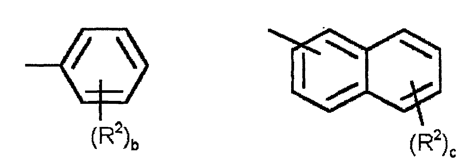
- As blocks having repeating units represented by the general Formula [1], poly(phenylene), poly(aniline), poly(phenylene ether) and poly(phenylene sulfide) may be mentioned. Among them in the Formula [1], poly(phenylene ether) in which X is represented by -O- is preferable, and specifically poly(1,4-phenylene ether), poly(2-methyl-1,4-phenylene ether), poly(2,6-dimethyl-1,4-phenylene ether), poly(2-phenyl-1,4-phenylene ether), poly(2,6-diphenyl-1,4-phenylene ether), poly(2-methyl-1,3-phenylene ether), poly(2,6-dimethyl-1,3-phenylene ether), poly(2-phenyl-1,3-phenylene ether), and poly(2,6-diphenyl-1,3-phenylene ether) may be mentioned.
- Among them, poly(1,4-phenylene ether), poly(2-phenyl-1,4-phenylene ether), and poly(2,6-diphenyl-1,4-phenylene ether) are more preferable, and poly(2-phenyl-1,4-phenylene ether) is still more preferable.
- Precursors of a block having repeating units represented by the general formula [1] may be manufactured by well-known methods. For example, a poly(phenylene ether) may be manufactured by an oxidation polymerization method in which phenol is oxidized in the presence of a catalyst, and by a method in which halogenated phenol is condensed in the presence of catalysts and alkalis (called Ullmann reaction).
- A precursor of a block means a polymer having reactive part giving a block copolymer by copolymerization reaction with other polymer having reacting part. (same hereinafter)
- On the other hand, a precursor of a block having repeating units represented by the above described general formula [2], for example, may be obtained by ring opening polymerization of a glycidyl ether having an aromatic ring represented by following formula.

- Specifically phenyl glycidyl ether, o-toluyl glycidyl ether, m-toluyl glycidyl ether, p-toluyl glycidyl ether, 2,3-dimethyl phenyl glycidyl ether, 2,4-dimethyl phenyl glycidyl ether, 2,5-dimethyl phenyl glycidyl ether, 2,6-dimethyl phenyl glycidyl ether, 2,3,4-trimethyl phenyl glycidyl ether, 2,4,6-trimethyl phenyl glycidyl ether, 2,3,4,6-tetramathyl phenyl glyeidyl ether, 2-ethyl phenyl glycidyl ether, 4-ethyl phenyl glycidyl ether, 2-propyl phenyl glycidyl ether, 4-n-propyl phenyl glycidyl ether, 4-propyl phenyl glycidyl ether, 2-butyl phenyl glycidyl ether, 4-butyl phenyl glycidyl ether, 4-i-propyl phenyl glycidyl ether, 2-biphenyl glycidyl ether, 4-biphenyl glycidyl ether, 1-naphthyl glycidyl ether and 2-naphthyl glycidyl ether may be mentioned. These may be used independently and may be used as a copolymer using a plurality of glycidyl ethers.
- Besides, it is also possible to use a precursor of a block obtained by copolymerizing glycidyl ethers having the above described aromatic ring, and epoxy compounds not including aromatic ring if needed.
- As epoxy compounds that do not include aromatic ring, for example, ethylene oxide, propylene oxide, 1,2-epoxy butane, cyclohexane epoxide, epifluorohydrin, epichlorohydrin, epibromohydrin, trifluoro propylene oxide, methyl glycidyl ether, ethyl glycidyl ether, propyl glycidyl ether and butyl glycidyl ether may be mentioned.
- When using a polymer or copolymer of above epoxy compound as one component of a precursor of a block, a high ratio of epoxy component may deteriorate the thermal resistance of the resulting block copolymer, and therefore a glycidyl ether component having an aromatic ring is preferably no less than 60 % by weight, and more preferably no less than 80 % by weight.
- As ring opening polymerization of glycidyl ethers having aromatic rings, or of the glycidyl ethers and epoxy compounds not including aromatic rings, many methods are known and each of these well-known polymerization methods may be used. A number of repeating units represented by the general formula [2] is preferably from 2 to 200, and more preferably is from 5 to 50.
- On the other hand, the above-described block having epoxy groups is obtained from a polymer having one or two or more of epoxy groups as a precursor of a block. However, even if a polymer having epoxy groups is not used as a precursor of a block, a block having epoxy groups may include a block in a block copolymer having a epoxy groups as a result.
- In blocks obtained from polymers having epoxy groups, a block comprising polymer having epoxy groups with aromatic rings in the polymer chain is more preferable, and it is still more preferable that it is a block having repeating units represented by general formula [3].

- In Formula [3], Ar2 represents a group selected from following structures.
 (In the above-described formulas, R3 represents an alkyl group with carbon numbers of from 1 to 6, alkoxy group with carbon numbers of from 1 to 6, or phenyl group, d is an integer of from 0 to 3 and e is an integer of from 0 to 2. When there are two or more R3, these may be the same, or may be different from each other. Y represents -O-, -S-, an alkylene group with carbon numbers of from 1 to 20, halogenated alkylene group with carbon numbers of from 1 to 10, or alkylene dioxy group with carbon numbers of from 1 to 20. When there are two or more Y, these may be the same, or may be different from each other.)
- Polymers having repeating units represented by the general formula [3] are synthesized by well-known methods. As the above described methods, a method in which diol compounds represented by HO-Ar2-OH are reacted with epichlorohydrin in the presence of alkali, and a method in which diol compounds and diglycidylether compounds are reacted may be mentioned.
- As diol compounds represented by HO-Ar2-OH, specifically, hydroquinone, resorcinol, catechol, 1,2-dihydroxy naphthalene, 1,4-dihydroxy naphthalene, 1,5-dihydroxy naphthalene, 2,6-dihydroxy naphthalene, 2,7-dihydroxy naphthalene, 4,4'-dihydroxy biphenyl, 2,4'-dihydroxy biphenyl, 2,2'-dihydroxy biphenyl, 4,4'-dihydroxy diphenylmethane, 1,1-bis(4-hydroxy phenyl)ethane, 2,2-bis(4-hydroxy phenyl)propane, 2,2-bis(4-hydroxy phenyl)butane, 1,1-bis(4-hydroxy phenyl)cyclohexane, 2,2-bis(4-hydroxy phenyl)-1,1,1,3,3,3-hexa fluoro propane, 1,1-bis(4-hydroxy phenyl)-1-phenyl ethane, bis(4-hydroxy phenyl)diphenylmethane, 9,9-bis(4-hydroxy phenyl)fluorene, α, α'-bis(4-hydroxy phenyl)-1,4-diisopropyl benzene, 4,4'-dihydroxy diphenyl ether, 2,2'-dihydroxy diphenyl ether, bis(4-hydroxy phenyl)sulfide, bis(2-hydroxy phenyl)sulfide, 1,2-his(4-hydroxy phenyl)ethane, 1,2-bis(4-hydroxy phenoxy)ethane, 1,2-bis(3-hydroxy phenoxy)ethane, 1,2-bis(4-hydroxy phenoxy)propane, 1,3-bis(4-hydroxy phenoxy)propane, 1,4-bis(4-hydroxy phenoxy)butane, 1,6-bis(4-hydroxy phenoxy)hexane and diethyleneglycol bis(4-hydroxy phenyl)ether may be mentioned.
- The number of repeating units composed of blocks obtained from polymers with repeating units represented by the general formula [3] is preferably from 2 to 200, and more preferably from 4 to 50.
- The polymer electrolyte in the present invention comprises a block copolymer which has one or more of the above described blocks in which sulfonic acid groups are introduced, and blocks in which sulfonic acid groups are not substantially introduced. As blocks in which sulfonic acid groups are not substantially introduced, a block comprising aromatic polyethers having repeating units represented by general formula [4] is preferable because of its high thermal resistance.
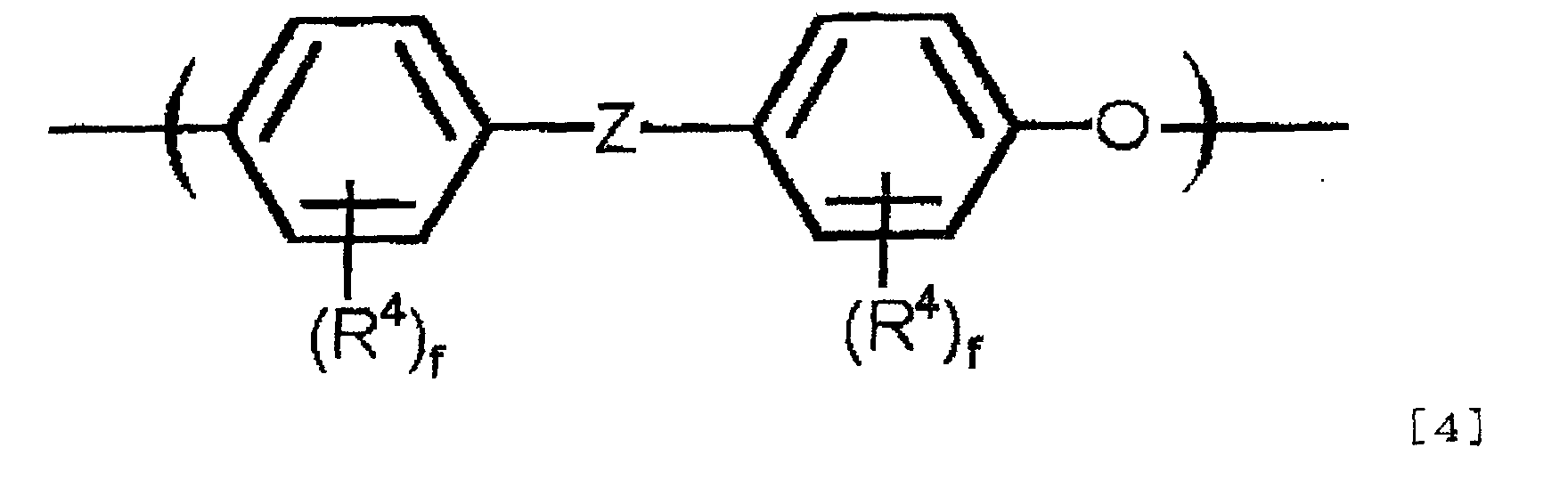
- In the general formula [4], R4 represents an alkyl group with carbon numbers of from 1 to 6, and f is an integer of from 0 to 4. When there are two or more R4, these may be the same, or may be different from each other. Z represents -CO- or -SO2-.
- Blocks comprising polyether ketones, blocks comprising polyether sulfones may be illustrated.
- Eapecially polyether sulfones in which Z is -SO2- in the general formula [4] are preferable because of their high solubility in solvents.
- Polyether sulfones that are examples of a precursor of blocks shown in the general formula [4] may be synthesized by polycondensation of 4,4'-dihydroxy diphenyl sulfone and 4,4'-dichloro diphenyl sulfone.
- The weight-average molecular weight of the precursor of the block obtained from polyether sulfone is preferably from 2000 to 500000, and more preferably from 8000 to 100000. When the molecular weight is smaller than 2000, film strength and thermal resistance of the copolymer may decrease, and when the molecular weight is larger than 500000, solubility may be small.
- A method for producing a polymer electrolyte of the present invention will be hereinafter described.
- There is in particular no limitation in methods for producing block copolymers by chemically bonding precursors of two or more kinds of blocks, and any suitable well-known methods for combining each block may be used.
- For example, in the case where poly(phenylene ether) that is an example of a precursor of a block shown by the general formula [1] as repeating unit, and polyether sulfone that is an example of a precursor of a block shown by the general formula [4] as repeating unit are copolymerized, a method of condensing poly(phenylene ether) having hydroxyl groups remaining at the end of the polymer chain, and polyether sulfone having halogens remaining at the end of the polymer chain under existence of alkali may be illustrated. Besides, when poly(phenylene ether) having hydroxyl groups remaining at the end of the polymer chain, and polyether sulfone having hydroxyl groups remaining at the end of the polymer chain are copolymerized, copolymerization may be conducted by a similar condensation reaction using dihalogenated compounds such as 4,4'-difluoro benzophenone or 4,4'-dichloro diphenyl sulfone as a linking agent for combining poly(phenylene ether) and polyether sulfone to obtain a block copolymer.
- On the other hand, when bonding poly(phenyl glycidyl ether) that is an example of a precursor of a block shown by the general formula [2] as repeating unit, and polyether sulfone that is an example of a precursor of a block shown by the general formula [4] as repeating unit, copolymerization may be conducted by converting end hydroxyl groups, which exist at the end of the polymer chain of polyether sulfone, into metal phenolate, by conducting ring opening polymerization of glycidyl ether including aromatic ring at the alkali metal phenolate as a polymerization starting point, and subsequently by conducting sulfonation.
- Besides, a method may be mentioned in which a precursor of a block is prepared by reacting phenyl glycidyl ether with glycidyl ethers having halogen usable for blocking reaction such as epichlorohydrin, and then the obtained precursor of a block is condensed with polyether sulfones with hydroxyl group remaining at the end of the polymer chain in the presence of alkali,
- Moreover, when polyether sulfone that is an example of a precursor of a block is bonded with an example of a precursor of a block shown by the general formula [3] as a repeating unit, a method may be mentioned in which a hydroxyl group remaining at the end of a polyether sulfone is reacted by a ring opening addition reaction with a glycidyl group remaining at the end of a polymer having epoxy group.
- Although it is possible for block copolymerization to be conducted in a molten state without solvent when using polyether sulfone as one of precursors of a block, it is preferable to conduct the reaction in a suitable solvent. Although as a solvent, aromatic hydrocarbons, ethers, ketones, amides, sulfones, and sulfoxides may be used, amides are preferable because of high solubility of polyether sulfone in amides. As amides, N,N-dimethylformamide, N,N-dimethyIacetamide and N-methyl pyrolidone may be mentioned.
- The reaction temperature of the block copolymerization reaction is preferably 20°C to 250°C, and more preferably it is 50°C to 200°C.
- In a block copolymer used for the present invention, it is preferable that the amount of blocks in which sulfonic acid groups are not substantially introduced is preferably 60 to 95 % by weight of the block copolymer, and more preferably it is 70 to 90 % by weight. When the amount of blocks in which sulfonic acid groups are not substantially introduced is more than 95 % by weight, since sulfonic acid equivalent in the block copolymer is small after introduction of sulfonic acid group, sufficient performance as a polymer electrolyte may not be obtained, and when it is less than 60 % by weight, water resistance of the block copolymer after introduction of sulfonic acid group may be insufficient.
- In a block copolymer used for the present invention, although a method of introducing sulfonic acid groups into a specific block is not limited, the following methods may be illustrated; (a) a method in which a precursor of a block with sulfonic acid groups introduced beforehand and a precursor of a block in which sulfonic acid groups are not substantially introduced are copolymerized, (b) a method in which a copolymer comprising a block in which sulfonic acid groups are to be introduced, and a block in which sulfonic acid groups are not to be substantially introduced is produced, and then sulfonic acid is selectively introduced into the block of this copolymer into which sulfonic acid groups are to be introduced. Regarding the precursor of a block in which sulfonic acid groups are introduced, since the sulfonic acid group may prevent copolymerization reaction, the method of above described (b) is preferable.
- In the above described method (a), a precursor of a block in which sulfonic acid groups are introduced may be prepared by sulfonating a precursor of a block. As sulfonating agents, well-known sulfonating agents, such as sulfuric acid which has no less than 90% of concentration, fuming sulfuric acid, chlorosulfonic acid, and SO3 may be used.
- In the above described method (b), as a method of selectively introducing sulfonic acid groups into a copolymer, a method (c) may be mentioned in which a functional group that exists in a block in which sulfonic acid groups are introduced, and does not exist in a block in which sulfonic acid groups are not substantially introduced is available. Besides, as other methods, a method may be proposed in which (d) difference in reactantivity to sulfonation reaction between a block in which sulfonic acid groups are introduced and a block in which sulfo groups are not substantially introduced is utilized.
- For example, when the sulfonation reaction is an electrophilic reaction, when sulfonation is conducted by concentrated sulfuric acid using a block copolymer comprising a block having aromatic rings that easily undergo an electrophilic reaction, and a block having aromatic rings that do not easily undergo an eletrophilic reaction, the former block will be selectively sulfonated.
- As a practical example of the above described method (d), a method for producing a polymer electrolyte comprising the steps of reacting the above described precursor of a block having repeating units represented by the general formula [1], [2], or [3] with a precursor of a block having repeating units represented by the general formula [4] to produce a block copolymer, and subsequently sulfonating the copolymer may be mentioned.
- For example, in the sulfonation reaction of an aromatic ring using sulfuric acid as a sulfonation agent, it is recognized that an aromatic ring of a block having repeating units represented by the general formula [4] has a low reactivity as compared with an aromatic ring of a block having repeating units represented by the general formula [1], [2], or [3].
- Therefore, if a block copolymer obtained by reacting a precursor of a block having repeating units represented by the general formula [4] and a precursor of a block having repeating units represented by the general formula [1], [2], or [3] is sulfonated with sulfuric acid under suitable conditions, a block copolymer in which sulfonic acid groups are selectively introduced into blocks having repeating units represented by the general formula [1], [2], or [3], and sulfonic acid groups are not substantially introduced to a block shown by the general formula [4] may be manufactured.
- In a step introducing sulfonic acid groups by sulfonation reaction, as sulfonating agents, well-known sulfonating agent such as sulfuric acid with concentration of no less than 90%, fuming sulfuric acid, chlorosulfonic acid and SO3 may be used. Among these, sulfuric acid with concentration of no less than 90% is preferable, and sulfuric acid of from 94 to 99 % by weight of concentration is more preferable.
- In addition, a small amount of organic solvents that do not participate in sulfonation reaction may be added with sulfuric acid so that sulfonation reaction of the block copolymer proceeds in homogeneous system.
- Dissolution in sulfuric acid and sulfonation of the block copolymer proceed simultaneously, and at room temperature, the reaction is usually completed in 2 to 20 hours to give a uniform solution. The resulting sulfonated block copolymer is recovered by pouring the obtained sulfuric acid solution into a large amount of water.
- The concentration of the block copolymer in sulfuric acid is preferably from 1 to 50 % by weight, and more preferably from 5 to 30 % by weight. Besides, a reaction temperature is preferably from 0°C to 80°C, and more preferably is from 20°C to 40°C.
- A polymer electrolyte is thus obtained. The polymer electrolyte of the present invention may include additives used for usual polymer, such as plasticizer, stabilizer, and releasing agent. Besides, intermolecular cross linkage may be introduced into the polymer electrolyte.
- In addition, the precursors of a block having repeating units represented by the general formulas [1] to [4] are cheap materials whose synthesis is already established and is performed in large quantities. Copolymers obtained by using the precursor as a raw material which is further sulfonated are also very cheap as compared with fluorine derived materials, such as Nafion ®.
- Porous membranes used in the present invention are used for further improvement in strength, plasticity, and durability of polymer electrolyte membranes by being complexed with polymer electrolytes. Therefore, although they may be used in any form made of any material as far as it satisfies the above described purpose of use, from the viewpoint of performing well as a polymer electrolyte membrane of solid polymer electrolyte type fuel cell, the membrane thickness is from 1 to 100 µm, preferably from 3 to 30 µm and more preferably from 5 to 20 µm; pore size is from 0.01 to 10 µm, preferably from 0.02 to 7 µm; and a porosity is from 20 to 98%, and preferably from 30 to 95%. When the membrane thickness of the porous membrane is too low, an effect of reinforcement on strength after combination or reinforcement effects, such as providing flexibility or durability, will become inadequate and gas is easy to leak (cross leak). When the membrane thickness is too great, electric resistance becomes higher and the obtained composite membrane is not desirable as a polymer electrolyte membrane of solid polymer electrolyte fuel cell. On the other hand, when the pore size is too small, impregnation of polymer electrolyte into pores of the membrane may become insufficient, and when it is too large, reinforcement effect to polymer electrolytes may become weak. When the porosity is too small, resistance as a polymer electrolyte membrane will become larger, and when it is too large, generally strength of porous membrane itself will become poor, and reinforcement effect will not be obtained.
- As material of the porous membrane, from viewpoint of thermal resistance and reinforcement effect of physical strength, aliphatic polymers or fluorine polymers are desirable.
- As aliphatic polymers suitably used, polyethylene, polypropylene and ethylene propylene copolymer may be illustrated. Polyethylenes used for the present invention include, for example, copolymers of ethylene and other monomers as well as ethylene homopolymer. Specifically, copolymers of ethylene and α-olefins referred to as linear low density polyethylene (LLDPE) are included. Besides, polypropylenes include, for example, propylene block copolymers and random copolymers (these are copolymers with e.g. ethylene and 1-butene).
- Besides, as fluorinated polymers, well-known thermoplastic resins having at least one carbon-fluorine bond in the molecule may be used without any limitation. Usually, resins having a structure where all or most of the hydrogens of aliphatic polymers are substituted by fluorine atoms are suitably used.
- Fluorinated resins, for example, may be poly(trifluoroethylene), poly(tetrafluoroethylene), poly(chloro trifluoroethylene), poly(tetrafluoroethylene-hexafluoropropylene), poly(tetrafluoroethylene-perfluoro alkylether) and poly(vinylidene fluoride), but the present invention is not limited by them. Among them, in the present invention, poly(tetrafluoroethylene) and poly(tetrafluoroethylene-hexafluoropropylene) are preferable, and poly(tetrafluoroethylene) is more preferable. From viewpoint of excellent mechanical strength, fluorinated resins having an average molecular weight of not less than 100000 are preferable.
- A polymer electrolyte membrane of the present invention is a polymer electrolyte membrane in which the above described polymer electrolyte and the above described porous membrane are combined. As combining methods, for example; a method in which a porous membrane is impregnated with a polymer electrolyte solution, the porous membrane is taken out, and then the solvent is evaporated to obtain a composite membrane; a method in which a polymer electrolyte solution is applied to a porous membrane, and then the solvent is evaporated to obtain a composite membrane; and a method in which a polymer electrolyte solution is contacted to a porous membrane under reduced pressure, then the pressure is returned to ordinary pressure to impregnate the solution into the porous membrane pores, and subsequently the solvent is evaporated to obtain a composite membrane may be illustrated. Above all, since a polymer electrolyte composite membrane having good appearance and maintaining physical properties of an original porous membrane may be produced, a method comprising,
- (i) a step in which pores of a porous membrane are impregnated with a solution (1) of a polymer electrolyte having a contact angle of less than 90° to the porous membrane,
- (ii) a step in which a remaining part of pores of the porous membrane is impregnated with a solution (2) of a polymer electrolyte having a larger contact angle than the contact angle of the above described solution (1) to the porous membrane, and
- (iii) a step in which the solvent is removed, is desirable.
-
- As the filling method of a polymer electrolyte, a method is adopted in which after a solution of a polymer electrolyte dissolved in a solvent is impregnated into a porous membrane, the solvent is removed. As methods of impregnating, a method in which the solution is applied or sprayed to the porous membrane may be adopted, or a method in which the porous membrane is immersed in the solution may be adopted. Besides, any of methods such as heating, reducing pressure, air-drying, and combination of these may be used as methods of removing solvent.
- A solvent of the polymer electrolyte solution (1) in step (i) will not be limited in particular, if it is a solvent in which a contact angle of the polymer electrolyte solution (1) to the porous membrane gives less than 90° when the electrolyte is dissolved. As these solvents, for example, solvents containing chlorine, such as dichloromethane, chloroform, 1,2-dichloroethane, chlorobenzene, and dichlorobenzene; alcohols, such as methanol, ethanol, and propanol; and mixtures of two or more kinds of these solvents may be used.
- Moreover, filling of an electrolyte in this step is conducted so that part of the pores of the porous membrane may remain not filled with an electrolyte. The amount of filling is usually less than 80% in volume of the pores, preferably less than 60%, and more preferably less than 40%. When too large degree of filling is conducted in this step, filling in the following step will become difficult.
- As solvent of solution (2) of polymer electrolyte in step of (ii), when an electrolyte is dissolved, a solvent giving a larger contact angle of a solution (2) of polyelectrolyte to the porous membrane than the contact angle of a solution (1) of polyelectrolyte used in step (i) is used. More preferably, a solvent giving a contact angle of not less than 90° to a porous membrane of solution (2) of polymer electrolyte is preferable.
- Moreover, if water still remains in a combined membrane after removing the solvent, a combined membrane with poor appearance may be obtained, because the combined membrane have bubbles, unevenness and low strength. Therefore when a solvent which easily absorbs water in air is used, a boiling point of the solvent is preferably no less than 110°C, and more preferably no less than 120°C.
- As such solvents, aprotic polar solvents, such as N,N-dimethylformamide, N,N-dimethylacetamide, N-methyl-2-pyrrolidone, and dimethyl sulfoxide, may be suitably used.
- In addition, once some of the pores of the porous membrane are filled with a polymer electrolyte in step (i), surface energy of the porous membrane partly filled with the polymer electrolyte may be raised, and therefore, a contact angle to the porous membrane of solution (1) and (2) of the polymer electrolyte is beforehand measured in the state where the pores of the porous membrane is not filled with the polymer electrolyte
- Moreover, the step (ii) is preferably carried out on supporting materials. By using supporting materials at the time of solvent removal, the solvent is volatilized from the opposite side of the surface of the porous membrane which touches the supporting material, and while the solvent is being removed, the supporting material continuously soaks up the polymer electrolyte solution by capillary action. Thus, a combined membrane comprising the porous membrane and the polymer electrolyte may be obtained in a state where the pores of the porous membrane are nearly completely filled with the polymer electrolyte.
- It is preferable that the surface energy of such a supporting material is no less than 20 dyne/cm, more preferably no less than 40 dyne/cm, and still more preferably no less than 50 dyne/cm. Filling of the polymer electrolyte solution between the porous membrane and the supporting materials is preferably conducted more quickly as the surface energy becomes larger.
- Moreover, as an example of supporting materials, plastic films such as polyethylene terephthalate (PET) films, metals and glasses may be suitably used. When a polymer electrolyte membrane of the present invention is used for fuel cell, there is in particular no limitation in thickness of the polymer electrolyte membrane, but the thickness is preferably from 3 to 200 µm, and more preferably from 4 to 100 µm, and still more preferably from 5 to 50 µm. When the thickness of the polymer electrolyte membrane is too small, a film strength that bears to practical use may not be obtained, and on the other hand, electric resistance will become high when the membrane thickness is too large, and then a polymer electrolyte membrane preferably used for a solid polymer electrolyte fuel cell may not be obtained. The polymer electrolyte membrane thickness is controllable by selecting appropriately the thickness of the porous membrane, the polymer electrolyte solution concentration, or an applying thickness of polymer electrolyte solution applied to the porous membrane.
- The fuel cell of the present invention will be hereinafter described.
- The fuel cell of the present invention is obtained using a polymer electrolyte membrane provided by the present invention, and manufactured by joining catalyst and conductive material as a current collector to both sides of the above described polymer electrolyte membrane.
- As the catalysts, as long as it is a catalyst that can activate oxidation-reduction reaction with hydrogen or oxygen, there will be in particular no limitation, and well-known catalysts may be used, and moreover it is preferable to use fine particle of platinum. Fine particles of platinum are preferably used in a state where they are carried on carbon with a shape of particle or fiber, such as activated carbon and graphites.
- Also in conductive materials as a current collector, although well-known materials may be used, since they can efficiently convey raw material gas to catalysts, porous carbon woven fabrics or carbon papers are preferable. As methods of joining platinum fine particles or carbon carrying platinum fine particles to porous carbon textile fabrics or carbon papers, and methods of joining them to a polymer electrolyte film, well-known methods, for example, a method indicated in J. Electrochem. Soc.: Electrochemical Science and Technology, 1988, Vol. 135(9), 2209 may be used.
- The present invention will be described referring to Examples hereinafter, however the present invention is not limited at all by these examples.
- A contact angle meter CA-DT-A type manufactured by KYOWA INTERFACE SCIENCE CO.,LTD. was used, and the contact angle to the base material of a liquid drop was measured.
- Proton conductivity measurement was carried out by alternating current impedance method under a conthtions of 80°C and 90% RH in high temperature humidistat using SI 1260 type IMPEDANCE/GAIN-PHASE ANALYZER, manufactured by Solartoron Co.,Ltd., and SI 1287 type potentiostat (ELECTROCHEMICAL INTERFACE, manufactured by Solartoron Instrument.). Unit is S/cm.
- A section of a composite membrane of a porous membrane and a polymer electrolyte membrane was observed using FE-SEM S900 Hitachi LTD., and FE-SEM-EDX analysis (field emission type scanning electron microscope-energy dispersion X ray analysis) was conducted for sulfur atoms in the section. The number of sulfur atoms was counted in a portion of polymer electrolyte layers on both surfaces of the composite membrane and in a portion where polymer electrolyte was combined with the porous membrane. When the number of counts of sulfur atoms was corrected in consideration of porosity of the porous membrane, and both of the counts were almost the same, it was judged that the polymer electrolyte was filled in the pores.
- The polymer electrolyte membrane was dipped into ion-exchanged water, and was boiled at 100°C for 2 hours, and subsequently the polymer electrolyte membrane was removed from the water. After surface water was wiped off, water absorption was measured according to the following equation using HR73 type halogen aquameter (Halogen Moisture Analyzer, manufactured by METTLER TOLEDO).
- Platinum catalyst carried on fibrous carbon and porous carbon woven fabrics as current collector were joined to both sides of a polymer electrolyte membrane. Humidified oxygen gas was supplied to one side of this unit, and humidified hydrogen gas to another side to evaluate power generation characteristics of this joined body.
- 99 mg anhydrous cuprous chloride and 266 mg 2-methyl benzoxazole were stirred in 1 ml toluene at room temperature under atmospheric condition for 15 minutes. 8.5 g 2-phenylphenol and 30 ml toluene were added to the mixture, and stirred at 50°C under oxygen atmosphere for five hours. Resulting mixture was poured into methanol including hydrochloric acid after completion of reaction, and a polymer was precipitated. The polymer was filtered and dried to obtain poly(2-phenylphenylene ether) (referred to as PE1, hereinafter).
- To a flask equipped with azeotropic distillation equipment 3.0 g Sumika Excel PES5003P (polyether sulfone with hydroxyl end groups, manufactured by Sumitomo Chemical Co., Ltd.), 0.75 g PE1, 0.04 g potassium carbonate, 15 ml N,N-dimethylacetamide (referred to as DMAc hereinafter) and 3 ml toluene were added. Mixture obtained was heated and agitated, and after water was removed off under azeotropic condition of toluene and water, toluene was distilled off. 0.05 g 4,4'-difluorobenzophenone was added, and heating and agitation were carried out at 160°C for five hours. Reaction liquid obtained was pored into a large quantity of acidic methanol with hydrochloric acid, obtained precipitate was recovered by filtration, and dried under reduced pressure at 80°C to obtain 3.8 g block copolymer.
- 2 g of the obtained block copolymer was stirred at room temperature with 20 ml of 98% sulfuric acid to obtain a uniform solution, and subsequently stirring was continued for further two hours. Obtained solution was pored into a large quantity of iced water, and obtained precipitate was recovered by filtration. Washing by mixer with ion-exchanged water was further repeated until washing liquid showed neutral, and drying at 40°C under reduced pressure was given to obtain a sulfonated block copolymer. Hereinafter, the polymer electrolyte may be referred to as (P1).
- Using same catalyst as manufacturing example 1, using chlorobenzene as solvent, oxidation polymerization of 12.25 g 2-phenylphenol and 1.49 g 4,4'-dihydroxy biphenyl as monomers was carried out to obtain poly(2-phenylphenylene ether) (referred to as PE2 hereinafter) having hydroxyl groups at both ends.
- Into a flask equipped with azeotropic distillation equipment, 50 g Sumika Excel PES5003P, 0.36 g potassium carbonate, 180 ml DMAc, and 25 ml toluene were added. Under nitrogen, and after heating and stirring were continued for two hours and water was removed under azeotropic condition of toluene and water, toluene was evaporated off. 9.5 g 4,4'-difluoro benzophenone was added, and heating and stirring were continued at 160°C for five hours. Resultant reaction liquid was pored into a large quantity of methanol, and generated precipitate was recovered by filtration. After resultant precipitate was stirred and washed with a large quantity of heated and refluxed acetone for five hours, removed out of acetone, and dried under reduced pressure at 80°C to obtain a 45g of polyether sulfone fluorinated at polymer chain ends.
- Into a flask equipped with azeotropic distillation equipment, 0.75 g PE2, 0.03 g potassium carbonate, 15 ml DMAc, and 3 ml toluene were added. Distillation removal of the toluene was carried out after water was removed under azeotropic condition of toluene and water. 3 g polyether sulfone fluorinated at polymer chain ends obtained above was added, and heating and stirring were carried out at 160°C for five hours. Reaction liquid obtained was pored into a large quantity of acidic methanol with hydrochloric acid, obtained precipitate was recovered by filtration, and dried under reduced pressure at 40°C to obtain 3.6 g block copolymer
- Block copolymer obtained was sulfonated by the same method as in Manufacturing Example 1 using 98% sulfuric acid to obtain a sulfonated block copolymer. Hereinafter, the polymer electrolyte may be referred to as (P2).
- 99 mg anhydrous cuprous chloride, and 65 mg N,N,N',N'-tetramethyl-1,3-propanediamine were stirred in 5 ml chlorobenzene at room temperature under atmospheric condition for 15 minutes. Into the mixture, 4.43 g 2,6-diphenyl phenol, 0.37 g 4,4'-dihydroxybiphenyl and 15 ml chlorobenzene were added, and the solution was stirred at 60°C under oxygen atmosphere for five hours. After completion of reaction, the resulting solution was poured into methanol including hydrochloric acid, a polymer was precipitated, and then filtered and dried to obtain poly(2,6-diphenylphenylene ether) having hydroxyl groups at both ends (hereinafter referred to as PE 3).
- Using 8.0 g Sumika Excel PES5003P, 2.0 g PE3, 0.2 g potassium carbonate, 0.26 g 4,4'-difluoro benzophenone, 50 ml DMAc, and 5 ml toluene, the same reaction as Manufacturing Example 1 was conducted to obtain 9.8 g block copolymer. Resulting block copolymer was sulfonated with 98% sulfuric acid to obtain a sulfonated block copolymer. Hereinafter, this polymer electrolyte may be referred to as (P3).
- A mixed solvent of chloroform / methanol =70 / 30 (weight ratio) was prepared, and the resultant mixed solvent and polymer (P1) were mixed to prepare a 2 % by weight solution. Hereinafter, this solution is referred to as (X). A boiling point of chloroform is 62°C and a boiling point methanol is 65°C. When the solution (X) was dropped on a porous membrane, a contact angle to the porous membrane of the liquid drop gave 25°.
- N,N-dimethylacetamide was mixed with polymer (P1), and 15 % by weight solution was prepared. Hereinafter, this solution is referred to as (Y). A boiling point of DMAc is 165.5°C. When the solution (Y) was dropped on a porous membrane, a contact angle to the porous membrane of the liquid drop was 120°.
- Manufacture of a polymer electrolyte membrane obtained by combining the polymer electrolyte (Pi) with a polyethylene porous membrane.
- P1 was dissolved in N,N-dimethylacetamide (hereinafter referred to as DMAc) at a concentration of 15 % by weight, and the solution was applied on a polyethylene porous membrane (9 µm of membrane thickness, 36% of porosity, 0.04 µm of pore size) currently fixed on a glass plate. Solvent was dried under ordinary pressure and a target polymer electrolyte membrane was obtained.
- Manufacture of a polymer electrolyte membrane obtained by combining the polymer electrolyte (P1) and a polytetrafluoroethylene porous membrane.
- P1 was dissolved in a methanol / dichloromethane mixed solvent at a concentration of 15 % by mass, and the solution was applied on a polytetrafluoroethylene porous membrane (15 µm of membrane thickness, 90% of porosity, 3.0 µm of pore size) currently fixed on a glass plate. Solvent was dried under ordinary pressure and a target polymer electrolyte membrane was obtained.
- Manufacture of a polymer electrolyte membrane obtained by combining the polymer electrolyte (P2) or (P3) and a polytetrafluoroethylene porous membrane.
- By a same procedure as in Example 2, a polymer electrolyte membrane obtained by combining the polymer electrolyte (P2) and a polytetrafluoroethylene porous membrane, or a polymer electrolyte membrane obtained by combining the (P3) and a polytetrafluoroethylene porous membrane were prepared.
- P1 was dissolved in DMAc at a concentration of 15 % by mass, and it was flowed wide spread on a glass plate. Solvent was dried under ordinary pressure and a target polymer electrolyte membrane was obtained.
- By a same procedure as in comparative example 1, the polymer electrolyte P2 or P3 was dissolved in DMAc at a concentration of 15 % by mass, and it was flowed wide spread on a glass plate. Solvent was dried under ordinary pressure and a target polymer electrolyte membrane was obtained.
- Polymer electrolyte membranes obtained in examples 1 to 4 and comparative examples 1 to 3 were measured for proton conductivity and water absorption. Results are summarized in following Table 1.
Polymer electrolyte Porous membrane material Proton conductivity (S/cm) Water absorption (%) Example 1 P1 Polyethylene 4.7×10⁻² 38 Example 2 P1 Polytetrafluo roethylene 8.5×10⁻² 60 Comparative example 1 P1 Not used 1.0×10⁻¹ 79 Example 3 P2 Polytetrafluo roethylene 7.2×10⁻² 49 Comparative example 2 P2 Not used 8.4×10⁻² 63 Example 4 P3 Polytetrafluo roethylene 4.3×10⁻² 30 Comparative example 3 P3 Not used 5.1×10⁻² 38 - Polymer electrolyte membranes obtained in examples 1 to 4 were evaluated for fuel cell characteristics. Cycles of operation and stop operation was repeated and evaluation was continued for one week. As a result, neither deterioration of fuel cell characteristic, nor gas leak were observed.
- On the other hand, when polymer electrolyte membranes obtained in comparative examples 1 to 3 were evaluated for same fuel cell characteristics, and after one week, gas leak was observed in all cases, and deterioration of characteristics was also observed.
- Apolytetrafluoroethylene porous membrane (15 µm of membrane thickness, 90% of porosity, 3.0 µm of pore size) was used as a porous membrane. The porous membrane was fixed on a glass plate. A surface energy of the glass plate showed no less than 20 dyne/cm. The solution (X) was dropped on a porous membrane, and the solution (X) was applied uniformly wide spread on the porous membrane using a wire coater. At this time, the polymer electrolyte solution impregnated into the porous membrane, reached on a backside of the glass plate, and the opaque porous membrane was observed to be transparent. Solvent was aix-dried. The porous membrane was observed opaque again. Then, the solution (Y) was dropped on the porous membrane, and the solution (Y) was uniformly applied wide spread on the porous membrane using a wire coater. At this time, the polymer electrolyte solution impregnated into Teflon ® porous membrane covered with the polymer electrolyte, reached on a back side of the glass plate, and the Teflon® porous membrane was observed to be transparent. Furthermore, the solution (Y) was dropped and a coating thickness was controlled using a bar coater having a clearance of 0.2 mm. The membrane was dried under ordinary pressure at 80°C. The membrane was then dipped in 1 mol/L of hydrochloric acid, and a polymer electrolyte composite membrane was obtained by subsequently washing with ion exchanged water.
- Using a same polytetrafluoroethylene porous membrane as in example 5 as a porous membrane, the porous membrane was fixed on a same glass plate as in Example 5. The solution (Y) was dropped on the porous membrane. At this time, a contact angle to the porous membrane of the liquid drop gave 120°. Using a wire coater, the solution (Y) was uniformly applied wide spread on the porous membrane. At this time, the Teflon® porous membrane was observed to be opaque. Furthermore the solution (Y) was dropped and coating thickness was controlled using a bar coater of 0.2 mm clearance. The membrane was dried under ordinary pressure at 80°C. The membrane was then dipped in one mol/l of hydrochloric acid, and a polymer electrolyte composite membrane was obtained by subsequently washing with ion exchange water.
- Using a same polytetrafluoroethylene porous membrane as in Example 5 as a porous membrane, the porous membrane was fixed on a same glass plate as in Example 5. The solution (X) was dropped on the porous membrane. A contact angle to the porous membrane of the liquid drop gave 25°. Solvent was air-dried after applying the solution (X) uniformly on the porous membrane wide spread using a wire coater. This operation was repeated 30 times. The membrane was then dipped in 1 mol/l of hydrochloric acid, and a polymer electrolyte composite membrane was obtained by subsequently washing with ion exchanged water.
- The solution (Y) was dropped on the same glass plate as in Example 5, and coating thickness was controlled using a bar coater of 0.2 mm clearance. The membrane was dried under ordinary pressure at 80°C. The membrane was then dipped in one mol/l of hydrochloric acid, and a polymer electrolyte composite membrane was obtained by subsequently washing with ion exchanged water.
- Composite membranes obtained in example 5, comparative example 4. and Comparative example 5, and electrolyte membranes obtained in comparative example 6 were evaluated for proton conductivity and for appearance, and results are shown in Table 2.
Appearance of composite membrane Proton conductivity (S/cm) Example 5 ○ 1.1×10⁻¹ Comparative example 4 ○ 0.2×10⁻¹ Comparative example 5 × 1.0×10-1 Comparative example 6 ○ 1.1×10⁻¹ ○: no unevenness and bubble not observed
×: unevenness and bubble observed. - The amount of filling of polymer electrolytes in porous membranes was measured for Example 5 and Comparative example 4. Results are shown in Table 3.
EDX analysis (number of counts of sulfur atom) Portion obtained only by polymer electrolyte membrane Portion where a polymer electrolyte is complexed Example 5 1500 1300 Comparative example 4 2700 250 - Composite membranes of Example 5 and Comparative example 5, and electrolyte membrane of comparative example 6 were evaluated for fuel cell characteristics. Cycles of operation and stop operation were repeated. Results after one week are shown in Table 4.
Fuel cell characteristics Example 5 Neither deterioration of characteristics nor gas leak were observed. Comparative example 5 Gas leak occurred and deterioration of characteristics was observed. Comparative example 6 Gas leak occurred and deterioration of characteristics was observed.
Claims (21)
- A polymer electrolyte membrane comprising a polymer electrolyte comprising;
a block copolymer comprising one or more blocks in which sulfonic acid groups are introduced and one or more blocks in which sulfonic acid groups are not substantially introduced, wherein at least one block in said block copolymer is a block having aromatic rings in the polymer chain, and
a porous membrane. - The polymer electrolyte membrane according to claim 1, wherein a block in which sulfonic acid groups are introduced is a block that has a structure having sulfonic acid groups on aromatic rings.
- The polymer electrolyte membrane according to claim 1, wherein a block in which sulfonic acid groups are introduced is a block in which sulfonic acid groups are introduced into a block having repeating units represented by general formula [1].(In the formula [1], X represents -O-, -S-, -NH-, or a direct bond;
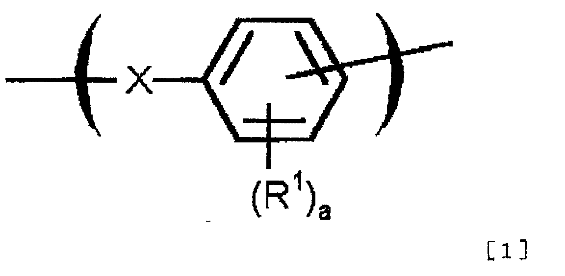
R1 represents an alkyl group with carbon numbers of from 1 to 6, an alkoxy group with carbon numbers of from 1 to 6, or a phenyl group; a represents integer of from 0 to 3. When there are two or more R1, these may be the same or different from each other.) - The polymer electrolyte membrane according to claim 3, wherein X is -O- in the general formula [1].
- The polymer electrolyte membrane according to claim 1, wherein a block in which sulfonic acid groups are introduced is a block in which sulfonic acid groups are introduced into a block having repeating units represented by general formula [2].(in the formula [2], Ar1 represents a group selected from following structures)
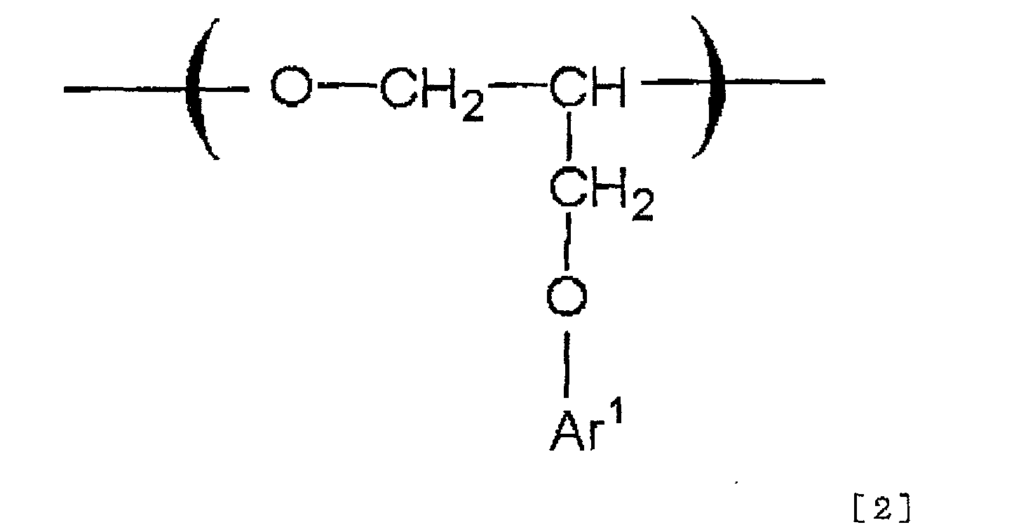 (In the above described formulas, R2 represents an alkyl group with carbon numbers of from 1 to 6, an alkoxy group with carbon numbers of from 1 to 6, a phenyl group, or a phenoxy group, b is an integer of from 0 to 4, and c is an integer of from 0 to 6. When there are two or more R2, these may be the same or different from each other.)
- The polymer electrolyte membrane according to claim 1, wherein a block in which sulfonic acid groups are introduced is a block in which sulfonic acid groups are introduced into a block having epoxy groups.
- The polymer electrolyte membrane according to claim 6, wherein a block having epoxy groups is a block in which sulfonic acid groups are introduced into a block having repeating units represented by general formula [3].(In formula [3], Ar2 represents a group selected from following structures.)
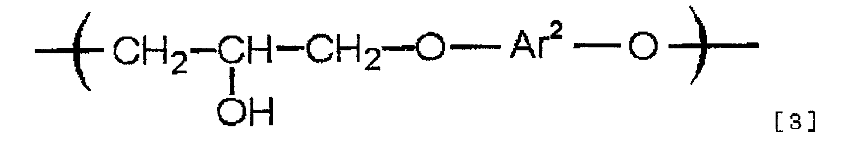
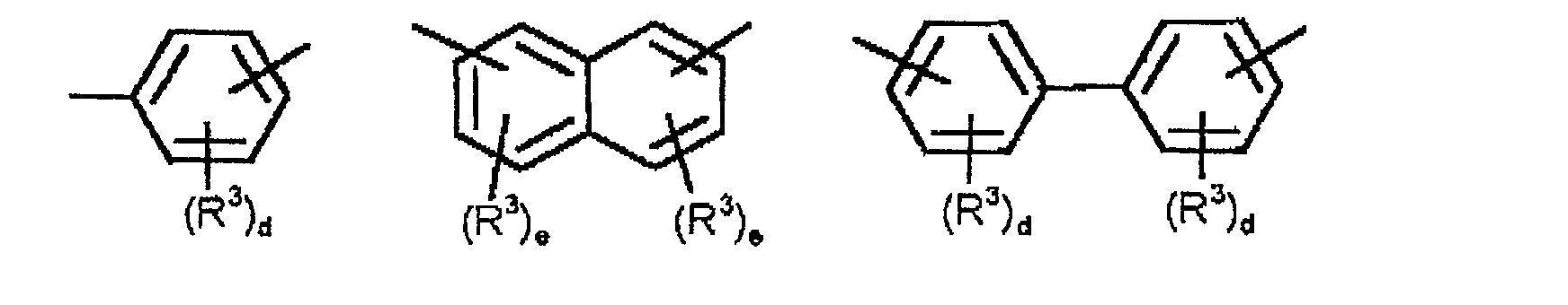 (In the above described formulas, R3 represents an alkyl group with carbon numbers of from 1 to 6, alkoxy group with carbon numbers of from 1 to 6, or phenyl group, d is an integer of from 0 to 3, and e is an integer of from 0 to 2. When there are two or more R3, these may be the same, or may be different from each other. Y represents -O- -S-, an alkylene group with carbon numbers of from 1 to 20, halogenated alkylene group with carbon numbers of from 1 to 10, or alkylenedioxy group with carbon numbers of from 1 to 20. When there are two or more Y, these may be the same or different from each other.)
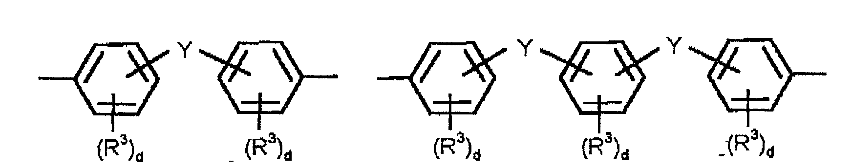
- The polymer electrolyte membrane according to claim 1, wherein a block in which sulfonic acid groups are not substantially introduced is an aromatic polyether having repeating units represented by general formula [4].(In the formula [4], R4 represents an alkyl group with carbon numbers of from 1 to 6, and f is an integer of from 0 to 4. When there are two or more R4, these may be the same or different from each other. Z represents -CO- or -SO2-.)

- The polymer electrolyte membrane according to claim 8, wherein Z is -SO2- in the general formula [4].
- The polymer electrolyte membrane according to claims 1 to 9, wherein a block in which sulfonic acid groups are not substantially introduced is from 60 to 95 % by weight of block copolymer.
- The polymer electrolyte membrane according to claim 1, wherein the polymer electrolyte is produced in a way that a precursor of a block having repeating units represented by general formula [1], [2] or [3], and a precursor of a block having repeating units represented by general formula [4] are reacted to produce a block copolymer, and subsequently said copolymer is sulfonated.
- The polymer electrolyte membrane according to claim 11, wherein a block copolymer is produced by sulfonating specific blocks in said block copolymer with sulfuric acid having a concentration of not less than 90%.
- The polymer electrolyte membrane according to claim 1, wherein the porous membrane comprises aliphatic polymers or fluorinated polymers.
- A fuel cell comprising the polymer electrolyte membrane according to any one of claims 1 to 13.
- A process for producing a polymer electrolyte membrane comprising the steps of:(i) impregnating pores of a porous membrane with a solution (1) of a polymer electrolyte having a contact angle of less than 90° to said porous membrane,(ii) impregnating a remaining part of pores of the porous membrane with a solution (2) of a polymer electrolyte having a larger contact angle than that of the solution (1) to said porous membrane, and(iii) removing the solvent.
- The process for producing a polymer electrolyte membrane according to claim 15, wherein the contact angle of the solution (2) of the polymer electrolyte to the porous membrane is not less than 90°.
- The process for producing a polymer electrolyte membrane according to claim 16, wherein the solvent of the solution of the polymer electrolyte having a contact angle of not less than 90° to a porous membrane has a boiling point of not less than 110°C.
- The process for producing a polymer electrolyte membrane according to claim 15, wherein the amount of filling of electrolyte in a step of (i) is less than 80% of pores of the porous membrane base material.
- The process for producing a polymer electrolyte membrane according to claim 15, wherein the polymer electrolyte comprises a block copolymer having one or more of blocks in which sulfonic acid groups are introduced and one or more blocks in which sulfonic acid groups are not substantially introduced, and in which at least one block in all of blocks is a block having aromatic rings in the polymer chain.
- The process for producing a polymer electrolyte membrane according to claim 15, wherein the porous membrane comprises aliphatic polymers or fluorinated polymers.
- A fuel cell comprising the polymer electrolyte membrane obtained by the process according to claims 15 to 20.
Applications Claiming Priority (4)
| Application Number | Priority Date | Filing Date | Title |
|---|---|---|---|
| JP2001201797A JP2003017090A (en) | 2001-07-03 | 2001-07-03 | Polymer electrolyte membrane and fuel cell using it |
| JP2001201797 | 2001-07-03 | ||
| JP2001234646 | 2001-08-02 | ||
| JP2001234646A JP4724976B2 (en) | 2001-08-02 | 2001-08-02 | Method for producing polymer electrolyte composite membrane and fuel cell |
Publications (3)
| Publication Number | Publication Date |
|---|---|
| EP1274147A2 true EP1274147A2 (en) | 2003-01-08 |
| EP1274147A3 EP1274147A3 (en) | 2005-04-06 |
| EP1274147B1 EP1274147B1 (en) | 2010-12-15 |
Family
ID=26618032
Family Applications (1)
| Application Number | Title | Priority Date | Filing Date |
|---|---|---|---|
| EP02014560A Expired - Fee Related EP1274147B1 (en) | 2001-07-03 | 2002-07-01 | Polymer electrolyte membrane and fuel cell |
Country Status (7)
| Country | Link |
|---|---|
| US (1) | US7601448B2 (en) |
| EP (1) | EP1274147B1 (en) |
| KR (1) | KR100944134B1 (en) |
| CN (1) | CN100519606C (en) |
| CA (1) | CA2392241A1 (en) |
| DE (1) | DE60238581D1 (en) |
| TW (1) | TW588076B (en) |
Cited By (16)
| Publication number | Priority date | Publication date | Assignee | Title |
|---|---|---|---|---|
| DE10258175A1 (en) * | 2002-12-12 | 2004-07-08 | General Motors Corp., Detroit | Block copolymers for use as solid polymer electrolytes e.g. in fuel cells have a segment with acidic substituents for proton transport and an acid-free segment giving mechanical integrity |
| EP1465277A1 (en) * | 2003-03-19 | 2004-10-06 | HONDA MOTOR CO., Ltd. | Solid polymer electrolyte and protonconducting membrane |
| WO2005056649A1 (en) | 2003-12-09 | 2005-06-23 | Jsr Corporation | Proton conducting membrane and process for producing the same |
| EP1662594A1 (en) * | 2003-06-30 | 2006-05-31 | Sumitomo Chemical Company, Limited | Polymer electrolyte composite film, method for production thereof and use thereof |
| EP1739780A1 (en) * | 2005-05-13 | 2007-01-03 | Fuji Photo Film Co., Ltd. | Solid electrolyte, membrane and electrode assembly, and fuel cell |
| WO2008009430A1 (en) * | 2006-07-20 | 2008-01-24 | Dsm Ip Assets B.V. | Electrolytic membrane |
| WO2008012222A2 (en) * | 2006-07-28 | 2008-01-31 | Leibniz-Institut Für Polymerforschung Dresden E.V. | Sulfonated polyarylene compounds, membrane material made therefrom, method for the production thereof, and use |
| EP1944820A1 (en) * | 2005-09-16 | 2008-07-16 | Sumitomo Chemical Company, Limited | Polymer electrolyte, polymer electrolyte membrane using same, membrane-electrode assembly and fuel cell |
| US7459505B2 (en) | 2005-05-03 | 2008-12-02 | General Motors Corporation | Block copolymers with acidic groups |
| WO2009007922A3 (en) * | 2007-07-10 | 2009-03-05 | Acta Spa | Anionic-exchange membranes and polymeric ionomers and process for their preparation |
| EP2037462A1 (en) * | 2006-07-04 | 2009-03-18 | Sumitomo Chemical Company, Limited | Polymer electrolyte emulsion and use thereof |
| KR100944134B1 (en) * | 2001-07-03 | 2010-02-24 | 스미또모 가가꾸 가부시끼가이샤 | Polymer electrolyte membrane and fuel cell |
| US7977394B2 (en) | 2005-05-03 | 2011-07-12 | GM Global Technology Operations LLC | Triblock copolymers with acidic groups |
| US7993792B2 (en) | 2006-07-26 | 2011-08-09 | GM Global Technology Operations LLC | Polymer blocks for PEM applications |
| EP2362473A1 (en) * | 2005-03-04 | 2011-08-31 | Ube Industries, Ltd. | Novel polymer electrolyte, polymer electrolyte composition, electrolyte membrane, and production method and use thereof |
| US8492460B2 (en) | 2006-07-28 | 2013-07-23 | GM Global Technology Operations LLC | Fluorinated polymer blocks for PEM applications |
Families Citing this family (30)
| Publication number | Priority date | Publication date | Assignee | Title |
|---|---|---|---|---|
| JP4052005B2 (en) * | 2001-12-20 | 2008-02-27 | 住友化学株式会社 | Production method of polymer electrolyte membrane |
| JP2006512428A (en) * | 2002-05-13 | 2006-04-13 | ポリフューエル・インコーポレイテッド | Ion conductive block copolymer |
| US7354679B2 (en) * | 2002-05-13 | 2008-04-08 | Polyfuel, Inc. | Ion conductive random copolymers |
| US7235164B2 (en) | 2002-10-18 | 2007-06-26 | Eksigent Technologies, Llc | Electrokinetic pump having capacitive electrodes |
| KR100496852B1 (en) * | 2002-08-23 | 2005-06-23 | 대주전자재료 주식회사 | Ion-exchangeable membrane and direct methanol fuel cell employing same |
| US20040175598A1 (en) * | 2002-12-02 | 2004-09-09 | Bliven David C. | Fuel cell power supply for portable computing device and method for fuel cell power control |
| KR100528020B1 (en) * | 2003-03-31 | 2005-11-15 | 세이코 엡슨 가부시키가이샤 | Method for forming functional porous layer, method for manufacturing fuel cell, electronic device, and automobile |
| KR101032633B1 (en) * | 2003-08-19 | 2011-05-06 | 김재운 | Method for preparing decomposing agent for toxic materials and gas mask including the decomposing agent |
| WO2005063854A1 (en) * | 2003-12-25 | 2005-07-14 | Sumitomo Chemical Company, Limited | Polymer electrolyte and use thereof |
| CA2511112A1 (en) * | 2004-06-30 | 2005-12-30 | Her Majesty The Queen In Right Of Canada, As Represented By The Minister Of National Research Council Of Canada | Synthesis of poly(arylene)s copolymers containing pendant sulfonic acid groups bonded to naphthalene as proton exchange membrane meterials |
| TWI294432B (en) * | 2004-12-14 | 2008-03-11 | Lg Chemical Ltd | Sulphonated multiblock copolymer and electrolyte membrane using the same |
| KR100657740B1 (en) * | 2004-12-22 | 2006-12-14 | 주식회사 엘지화학 | Branched and sulphonated multi block copolymer and electrolyte membrane using the same |
| US20070004900A1 (en) * | 2005-05-02 | 2007-01-04 | Gm Global Technology Operations, Inc. | Triblock copolymers with acidic groups |
| JP2007122960A (en) * | 2005-10-26 | 2007-05-17 | Toshiba Corp | Fuel cell |
| KR100717800B1 (en) * | 2005-11-22 | 2007-05-11 | 삼성에스디아이 주식회사 | Polymer membrane for fuel cell, method of preparing same and membrane-electrode assembly for fuel cell comprising same |
| DK1957794T3 (en) | 2005-11-23 | 2014-08-11 | Eksigent Technologies Llc | Electrokinetic pump designs and drug delivery systems |
| JP4940692B2 (en) * | 2006-02-22 | 2012-05-30 | トヨタ自動車株式会社 | Fuel cell electrolyte materials |
| KR100752072B1 (en) * | 2006-07-25 | 2007-08-27 | 한국에너지기술연구원 | Organic-inorganic composite polymer electrolyte membrane for fuel cells and its preparation method |
| US20080114149A1 (en) * | 2006-11-14 | 2008-05-15 | General Electric Company | Polymers comprising superacidic groups, and uses thereof |
| US7867592B2 (en) * | 2007-01-30 | 2011-01-11 | Eksigent Technologies, Inc. | Methods, compositions and devices, including electroosmotic pumps, comprising coated porous surfaces |
| WO2009076134A1 (en) * | 2007-12-11 | 2009-06-18 | Eksigent Technologies, Llc | Electrokinetic pump with fixed stroke volume |
| TW200948889A (en) * | 2008-02-01 | 2009-12-01 | Sumitomo Chemical Co | Polyelectrolyte composition, method of production of same, and fuel cell |
| CN103813814A (en) | 2011-05-05 | 2014-05-21 | 艾克西根特技术有限公司 | Gel coupling for electrokinetic delivery system |
| CN102386346B (en) * | 2011-11-22 | 2014-01-08 | 深圳市金钒能源科技有限公司 | Production method for integrated component of seal ring and ionic membrane |
| CN105061703B (en) | 2013-01-14 | 2019-03-15 | 科腾聚合物美国有限责任公司 | Anion exchange block copolymer, manufacture and application thereof |
| EP3147965B1 (en) * | 2015-09-25 | 2018-11-21 | Samsung Electronics Co., Ltd. | Composite membrane, preparing method thereof, negative electrode structure including the composite membrane, and lithium secondary battery including the negative electrode structure |
| CN106816617B (en) * | 2015-11-30 | 2020-07-03 | 东丽先端材料研究开发(中国)有限公司 | Preparation method of polymer composite electrolyte membrane |
| CA3031591A1 (en) | 2016-07-25 | 2018-02-01 | Tokyo Institute Of Technology | Electrolyte membrane and method for producing same |
| CN108232261B (en) * | 2016-12-21 | 2022-03-22 | 东丽先端材料研究开发(中国)有限公司 | Polymer composite electrolyte membrane and preparation method thereof |
| CN112029103A (en) * | 2020-08-05 | 2020-12-04 | 杭州晟聚环保科技有限公司 | Preparation of acid-base ion modified polymer and porous membrane thereof |
Citations (2)
| Publication number | Priority date | Publication date | Assignee | Title |
|---|---|---|---|---|
| WO2000063995A1 (en) | 1999-04-20 | 2000-10-26 | Lynntech, Inc. | Process of making a composite membrane |
| JP2004089976A (en) | 2002-08-30 | 2004-03-25 | Nordson Kk | Method for spraying liquid |
Family Cites Families (25)
| Publication number | Priority date | Publication date | Assignee | Title |
|---|---|---|---|---|
| US542979A (en) * | 1895-07-16 | yon siemens | ||
| FR2097260A5 (en) * | 1970-06-18 | 1972-03-03 | Rhone Poulenc Sa | |
| JPS62252074A (en) | 1986-04-25 | 1987-11-02 | Fuji Electric Co Ltd | Matrix for fuel cell |
| US4849311A (en) | 1986-09-24 | 1989-07-18 | Toa Nenryo Kogyo Kabushiki Kaisha | Immobilized electrolyte membrane |
| JPH0768377B2 (en) | 1987-07-20 | 1995-07-26 | 東燃株式会社 | Electrolyte thin film |
| US4865925A (en) * | 1987-12-14 | 1989-09-12 | Hughes Aircraft Company | Gas permeable electrode for electrochemical system |
| JPH02294338A (en) * | 1989-05-09 | 1990-12-05 | Asahi Glass Co Ltd | Novel multi-layered ion exchange membrane |
| JPH04204522A (en) | 1990-11-30 | 1992-07-24 | Tonen Corp | Electrolytic thin film |
| SG73410A1 (en) * | 1992-06-13 | 2000-06-20 | Hoechst Ag | Polymer electrolyte membrane and process for the production thereof |
| JPH0629032A (en) | 1992-07-08 | 1994-02-04 | Sumitomo Electric Ind Ltd | High polymer electrolyte film and its manufacture |
| FR2695131B1 (en) | 1992-09-01 | 1994-09-30 | Alsthom Cge Alcatel | Solid proton conducting polymer electrolyte. |
| JP3345086B2 (en) | 1993-03-19 | 2002-11-18 | 旭硝子株式会社 | Method for producing multilayer anion exchange membrane and method for recovering acid |
| US5834523A (en) * | 1993-09-21 | 1998-11-10 | Ballard Power Systems, Inc. | Substituted α,β,β-trifluorostyrene-based composite membranes |
| DE4422158A1 (en) * | 1994-06-24 | 1996-01-04 | Hoechst Ag | Homogeneous polymer alloys based on sulfonated, aromatic polyether ketones |
| US5795668A (en) * | 1994-11-10 | 1998-08-18 | E. I. Du Pont De Nemours And Company | Fuel cell incorporating a reinforced membrane |
| JP4062364B2 (en) | 1995-03-20 | 2008-03-19 | バスフ・ヒュエル・セル・ゲーエムベーハー | Sulfonated polyetherketone, process for its preparation and its use as membrane manufacture |
| JPH09194609A (en) | 1996-01-25 | 1997-07-29 | Sumitomo Electric Ind Ltd | Ion-exchange membrane and its preparation |
| JP3861367B2 (en) * | 1996-04-18 | 2006-12-20 | 住友化学株式会社 | POLYMER ELECTROLYTE, MANUFACTURING METHOD THEREOF, AND FUEL CELL COMPRISING THE SAME |
| JP3724064B2 (en) | 1996-06-28 | 2005-12-07 | 住友化学株式会社 | Polymer electrolyte for fuel cell and fuel cell |
| US6248469B1 (en) | 1997-08-29 | 2001-06-19 | Foster-Miller, Inc. | Composite solid polymer electrolyte membranes |
| DE19909028A1 (en) | 1999-03-02 | 2000-09-07 | Aventis Res & Tech Gmbh & Co | Sulfonated aromatic polymers, membrane containing these polymers, process for their preparation and their use |
| JP4802354B2 (en) | 1999-12-27 | 2011-10-26 | 住友化学株式会社 | POLYMER ELECTROLYTE AND METHOD FOR PRODUCING THE SAME |
| DE60143635D1 (en) * | 2000-02-15 | 2011-01-27 | Asahi Glass Co Ltd | Block polymer, process for producing polymer and solid polymer electrolyte fuel cell |
| KR100408877B1 (en) * | 2001-02-09 | 2003-12-18 | 이무성 | Styrene-diene copolymers by fluorination and sulfonation and its preparation and polymer electrolyte membrane using the said copolymers for fuel cell |
| TW588076B (en) * | 2001-07-03 | 2004-05-21 | Sumitomo Chemical Co | Polymer electrolyte membrane and fuel cell |
-
2002
- 2002-06-28 TW TW091114433A patent/TW588076B/en active
- 2002-06-28 CA CA002392241A patent/CA2392241A1/en not_active Abandoned
- 2002-06-28 US US10/183,523 patent/US7601448B2/en not_active Expired - Fee Related
- 2002-06-29 KR KR1020020037421A patent/KR100944134B1/en not_active IP Right Cessation
- 2002-07-01 DE DE60238581T patent/DE60238581D1/en not_active Expired - Lifetime
- 2002-07-01 CN CNB021403449A patent/CN100519606C/en not_active Expired - Fee Related
- 2002-07-01 EP EP02014560A patent/EP1274147B1/en not_active Expired - Fee Related
Patent Citations (2)
| Publication number | Priority date | Publication date | Assignee | Title |
|---|---|---|---|---|
| WO2000063995A1 (en) | 1999-04-20 | 2000-10-26 | Lynntech, Inc. | Process of making a composite membrane |
| JP2004089976A (en) | 2002-08-30 | 2004-03-25 | Nordson Kk | Method for spraying liquid |
Cited By (30)
| Publication number | Priority date | Publication date | Assignee | Title |
|---|---|---|---|---|
| KR100944134B1 (en) * | 2001-07-03 | 2010-02-24 | 스미또모 가가꾸 가부시끼가이샤 | Polymer electrolyte membrane and fuel cell |
| DE10258175A1 (en) * | 2002-12-12 | 2004-07-08 | General Motors Corp., Detroit | Block copolymers for use as solid polymer electrolytes e.g. in fuel cells have a segment with acidic substituents for proton transport and an acid-free segment giving mechanical integrity |
| US7351775B2 (en) | 2002-12-12 | 2008-04-01 | General Motors Corporation | Ion conductive membrane made from a block copolymer and methods of making a block copolymer |
| EP1465277A1 (en) * | 2003-03-19 | 2004-10-06 | HONDA MOTOR CO., Ltd. | Solid polymer electrolyte and protonconducting membrane |
| US7030206B2 (en) | 2003-03-19 | 2006-04-18 | Honda Motor Co., Ltd. | Polymer electrolyte and proton-conducting membrane |
| EP1662594A4 (en) * | 2003-06-30 | 2010-07-28 | Sumitomo Chemical Co | Polymer electrolyte composite film, method for production thereof and use thereof |
| EP1662594A1 (en) * | 2003-06-30 | 2006-05-31 | Sumitomo Chemical Company, Limited | Polymer electrolyte composite film, method for production thereof and use thereof |
| EP1693405A1 (en) * | 2003-12-09 | 2006-08-23 | JSR Corporation | Proton conducting membrane and process for producing the same |
| WO2005056649A1 (en) | 2003-12-09 | 2005-06-23 | Jsr Corporation | Proton conducting membrane and process for producing the same |
| EP1693405A4 (en) * | 2003-12-09 | 2008-02-27 | Jsr Corp | Proton conducting membrane and process for producing the same |
| US8058365B2 (en) | 2003-12-09 | 2011-11-15 | Jsr Corporation | Proton conducting membrane and process for producing the same |
| EP2362473A1 (en) * | 2005-03-04 | 2011-08-31 | Ube Industries, Ltd. | Novel polymer electrolyte, polymer electrolyte composition, electrolyte membrane, and production method and use thereof |
| US8710176B2 (en) | 2005-03-04 | 2014-04-29 | Ube Industries, Ltd. | Method for producing a sulfonated polyarylether block copolymer |
| US9005843B2 (en) | 2005-03-04 | 2015-04-14 | Ube Industries, Ltd. | Polymer electrolyte composition |
| US8263672B2 (en) | 2005-05-03 | 2012-09-11 | GM Global Technology Operations LLC | Triblock copolymers with acidic groups |
| US7459505B2 (en) | 2005-05-03 | 2008-12-02 | General Motors Corporation | Block copolymers with acidic groups |
| US7977394B2 (en) | 2005-05-03 | 2011-07-12 | GM Global Technology Operations LLC | Triblock copolymers with acidic groups |
| EP1739780A1 (en) * | 2005-05-13 | 2007-01-03 | Fuji Photo Film Co., Ltd. | Solid electrolyte, membrane and electrode assembly, and fuel cell |
| US7442459B2 (en) | 2005-05-13 | 2008-10-28 | Fujifilm Corporation | Solid electrolyte, membrane and electrode assembly, and fuel cell |
| EP1944820A4 (en) * | 2005-09-16 | 2010-02-03 | Sumitomo Chemical Co | Polymer electrolyte, polymer electrolyte membrane using same, membrane-electrode assembly and fuel cell |
| EP1944820A1 (en) * | 2005-09-16 | 2008-07-16 | Sumitomo Chemical Company, Limited | Polymer electrolyte, polymer electrolyte membrane using same, membrane-electrode assembly and fuel cell |
| EP2037462A1 (en) * | 2006-07-04 | 2009-03-18 | Sumitomo Chemical Company, Limited | Polymer electrolyte emulsion and use thereof |
| EP2037462A4 (en) * | 2006-07-04 | 2015-01-14 | Sumitomo Chemical Co | Polymer electrolyte emulsion and use thereof |
| WO2008009430A1 (en) * | 2006-07-20 | 2008-01-24 | Dsm Ip Assets B.V. | Electrolytic membrane |
| US7993792B2 (en) | 2006-07-26 | 2011-08-09 | GM Global Technology Operations LLC | Polymer blocks for PEM applications |
| US8163864B2 (en) | 2006-07-28 | 2012-04-24 | Leibniz-Institut Fuer Polymerforschung Dresden E.V. | Sulfonated polyarylene compounds, membrane material made therefrom, method for the production thereof and use |
| US8492460B2 (en) | 2006-07-28 | 2013-07-23 | GM Global Technology Operations LLC | Fluorinated polymer blocks for PEM applications |
| WO2008012222A3 (en) * | 2006-07-28 | 2008-04-24 | Leibniz Inst Polymerforschung | Sulfonated polyarylene compounds, membrane material made therefrom, method for the production thereof, and use |
| WO2008012222A2 (en) * | 2006-07-28 | 2008-01-31 | Leibniz-Institut Für Polymerforschung Dresden E.V. | Sulfonated polyarylene compounds, membrane material made therefrom, method for the production thereof, and use |
| WO2009007922A3 (en) * | 2007-07-10 | 2009-03-05 | Acta Spa | Anionic-exchange membranes and polymeric ionomers and process for their preparation |
Also Published As
| Publication number | Publication date |
|---|---|
| US7601448B2 (en) | 2009-10-13 |
| CA2392241A1 (en) | 2003-01-03 |
| TW588076B (en) | 2004-05-21 |
| CN100519606C (en) | 2009-07-29 |
| KR20030004097A (en) | 2003-01-14 |
| CN1394889A (en) | 2003-02-05 |
| EP1274147A3 (en) | 2005-04-06 |
| US20030044669A1 (en) | 2003-03-06 |
| KR100944134B1 (en) | 2010-02-24 |
| EP1274147B1 (en) | 2010-12-15 |
| DE60238581D1 (en) | 2011-01-27 |
Similar Documents
| Publication | Publication Date | Title |
|---|---|---|
| US7601448B2 (en) | Polymer electrolyte membrane and fuel cell | |
| JP6891271B2 (en) | Polymer electrolyte membrane, membrane electrode assembly, and polymer electrolyte fuel cell | |
| US10535890B2 (en) | Polymer electrolyte membrane, method for fabricating same, and membrane-electrode assembly comprising same | |
| JPWO2019188572A1 (en) | Electrolyte membrane | |
| CN1723233B (en) | Block copolymer and application thereof | |
| Li et al. | Development of a crosslinked pore-filling membrane with an extremely low swelling ratio and methanol crossover for direct methanol fuel cells | |
| JP2003288916A (en) | Direct methanol fuel cell membrane and its manufacturing method | |
| JP2006066391A (en) | Polymer electrolyte fuel cell | |
| JP4771702B2 (en) | Polymer solid electrolyte membrane with reinforcing material | |
| JP7188204B2 (en) | Composite electrolyte membrane and membrane electrode assembly using the same, polymer electrolyte fuel cell | |
| JP2003017090A (en) | Polymer electrolyte membrane and fuel cell using it | |
| JP2006269266A (en) | Compound solid polyelectrolyte membrane having reinforcement material | |
| JP4724976B2 (en) | Method for producing polymer electrolyte composite membrane and fuel cell | |
| JP2008181882A (en) | Polymer electrolyte, and its manufacturing method | |
| JP2002319414A (en) | Polymer electrolyte | |
| KR100880092B1 (en) | Surface modification of hydrocarbon-based polymer electrolyte membrane | |
| JP2004303541A (en) | Polymer laminated film, its method of manufacture and its usage | |
| JP2002260687A (en) | High polymer electrolyte | |
| JP4720090B2 (en) | Sulfonic acid group-containing polymer electrolyte membrane and article using the same | |
| JP3651683B1 (en) | Sulfonic acid group-containing polymer compound, ion conductive membrane obtained thereby, and article using the same | |
| JP2021052001A (en) | Composite electrolyte membrane and membrane electrode composite using the same, and polymer electrolyte fuel cell | |
| JP2022094934A (en) | Electrolyte membrane, electrolyte membrane with catalyst layer, membrane electrode complex, and solid polymer type fuel cell | |
| WO2021054252A1 (en) | Composite polymer electrolyte membrane, electrolyte membrane with catalyst layer, membrane-electrode assembly, and solid polymer fuel cell | |
| JP2021051994A (en) | Composite polymer electrolyte membrane, electrolyte membrane with catalyst layer, membrane electrode complex and solid polymer fuel cell | |
| JP2005116397A (en) | Forming method of sulfonated polymer film |
Legal Events
| Date | Code | Title | Description |
|---|---|---|---|
| PUAI | Public reference made under article 153(3) epc to a published international application that has entered the european phase |
Free format text: ORIGINAL CODE: 0009012 |
|
| AK | Designated contracting states |
Kind code of ref document: A2 Designated state(s): AT BE BG CH CY CZ DE DK EE ES FI FR GB GR IE IT LI LU MC NL PT SE SK TR |
|
| AX | Request for extension of the european patent |
Free format text: AL;LT;LV;MK;RO;SI |
|
| RAP1 | Party data changed (applicant data changed or rights of an application transferred) |
Owner name: SUMITOMO CHEMICAL COMPANY, LIMITED |
|
| PUAL | Search report despatched |
Free format text: ORIGINAL CODE: 0009013 |
|
| RIC1 | Information provided on ipc code assigned before grant |
Ipc: 7C 08J 5/22 B Ipc: 7H 01M 2/14 B Ipc: 7B 01D 71/80 B Ipc: 7H 01M 8/10 A |
|
| AK | Designated contracting states |
Kind code of ref document: A3 Designated state(s): AT BE BG CH CY CZ DE DK EE ES FI FR GB GR IE IT LI LU MC NL PT SE SK TR |
|
| AX | Request for extension of the european patent |
Extension state: AL LT LV MK RO SI |
|
| 17P | Request for examination filed |
Effective date: 20050920 |
|
| AKX | Designation fees paid |
Designated state(s): DE FR GB IT |
|
| 17Q | First examination report despatched |
Effective date: 20051024 |
|
| 17Q | First examination report despatched |
Effective date: 20051024 |
|
| GRAP | Despatch of communication of intention to grant a patent |
Free format text: ORIGINAL CODE: EPIDOSNIGR1 |
|
| GRAS | Grant fee paid |
Free format text: ORIGINAL CODE: EPIDOSNIGR3 |
|
| GRAA | (expected) grant |
Free format text: ORIGINAL CODE: 0009210 |
|
| AK | Designated contracting states |
Kind code of ref document: B1 Designated state(s): DE FR GB IT |
|
| REG | Reference to a national code |
Ref country code: GB Ref legal event code: FG4D |
|
| REF | Corresponds to: |
Ref document number: 60238581 Country of ref document: DE Date of ref document: 20110127 Kind code of ref document: P |
|
| PLBE | No opposition filed within time limit |
Free format text: ORIGINAL CODE: 0009261 |
|
| STAA | Information on the status of an ep patent application or granted ep patent |
Free format text: STATUS: NO OPPOSITION FILED WITHIN TIME LIMIT |
|
| 26N | No opposition filed |
Effective date: 20110916 |
|
| PG25 | Lapsed in a contracting state [announced via postgrant information from national office to epo] |
Ref country code: IT Free format text: LAPSE BECAUSE OF FAILURE TO SUBMIT A TRANSLATION OF THE DESCRIPTION OR TO PAY THE FEE WITHIN THE PRESCRIBED TIME-LIMIT Effective date: 20101215 |
|
| REG | Reference to a national code |
Ref country code: DE Ref legal event code: R097 Ref document number: 60238581 Country of ref document: DE Effective date: 20110916 |
|
| GBPC | Gb: european patent ceased through non-payment of renewal fee |
Effective date: 20110701 |
|
| REG | Reference to a national code |
Ref country code: FR Ref legal event code: ST Effective date: 20120330 |
|
| PG25 | Lapsed in a contracting state [announced via postgrant information from national office to epo] |
Ref country code: FR Free format text: LAPSE BECAUSE OF NON-PAYMENT OF DUE FEES Effective date: 20110801 |
|
| PG25 | Lapsed in a contracting state [announced via postgrant information from national office to epo] |
Ref country code: GB Free format text: LAPSE BECAUSE OF NON-PAYMENT OF DUE FEES Effective date: 20110701 |
|
| PGFP | Annual fee paid to national office [announced via postgrant information from national office to epo] |
Ref country code: DE Payment date: 20130626 Year of fee payment: 12 |
|
| REG | Reference to a national code |
Ref country code: DE Ref legal event code: R119 Ref document number: 60238581 Country of ref document: DE |
|
| PG25 | Lapsed in a contracting state [announced via postgrant information from national office to epo] |
Ref country code: DE Free format text: LAPSE BECAUSE OF NON-PAYMENT OF DUE FEES Effective date: 20150203 |
|
| REG | Reference to a national code |
Ref country code: DE Ref legal event code: R119 Ref document number: 60238581 Country of ref document: DE Effective date: 20150203 |