EP1273879B1 - Method and measuring device for measuring at least one property of a moving web - Google Patents
Method and measuring device for measuring at least one property of a moving web Download PDFInfo
- Publication number
- EP1273879B1 EP1273879B1 EP02014650A EP02014650A EP1273879B1 EP 1273879 B1 EP1273879 B1 EP 1273879B1 EP 02014650 A EP02014650 A EP 02014650A EP 02014650 A EP02014650 A EP 02014650A EP 1273879 B1 EP1273879 B1 EP 1273879B1
- Authority
- EP
- European Patent Office
- Prior art keywords
- measuring
- web
- moving web
- reference part
- negative pressure
- Prior art date
- Legal status (The legal status is an assumption and is not a legal conclusion. Google has not performed a legal analysis and makes no representation as to the accuracy of the status listed.)
- Expired - Lifetime
Links
- 238000000034 method Methods 0.000 title claims description 20
- 238000005259 measurement Methods 0.000 claims description 19
- 230000000694 effects Effects 0.000 claims description 16
- 239000000463 material Substances 0.000 claims description 4
- 230000005611 electricity Effects 0.000 claims description 3
- 230000003287 optical effect Effects 0.000 claims description 2
- 239000003570 air Substances 0.000 claims 20
- 239000012080 ambient air Substances 0.000 claims 2
- 239000000428 dust Substances 0.000 description 3
- 238000004140 cleaning Methods 0.000 description 2
- 239000012535 impurity Substances 0.000 description 2
- 230000006698 induction Effects 0.000 description 2
- 238000004519 manufacturing process Methods 0.000 description 2
- RYGMFSIKBFXOCR-UHFFFAOYSA-N Copper Chemical compound [Cu] RYGMFSIKBFXOCR-UHFFFAOYSA-N 0.000 description 1
- 229910000831 Steel Inorganic materials 0.000 description 1
- 239000004411 aluminium Substances 0.000 description 1
- XAGFODPZIPBFFR-UHFFFAOYSA-N aluminium Chemical compound [Al] XAGFODPZIPBFFR-UHFFFAOYSA-N 0.000 description 1
- 229910052782 aluminium Inorganic materials 0.000 description 1
- 239000010949 copper Substances 0.000 description 1
- 229910052802 copper Inorganic materials 0.000 description 1
- 229920006255 plastic film Polymers 0.000 description 1
- 239000002985 plastic film Substances 0.000 description 1
- 239000000523 sample Substances 0.000 description 1
- 239000010959 steel Substances 0.000 description 1
- 239000004753 textile Substances 0.000 description 1
Images


Classifications
-
- G—PHYSICS
- G01—MEASURING; TESTING
- G01B—MEASURING LENGTH, THICKNESS OR SIMILAR LINEAR DIMENSIONS; MEASURING ANGLES; MEASURING AREAS; MEASURING IRREGULARITIES OF SURFACES OR CONTOURS
- G01B21/00—Measuring arrangements or details thereof, where the measuring technique is not covered by the other groups of this subclass, unspecified or not relevant
- G01B21/02—Measuring arrangements or details thereof, where the measuring technique is not covered by the other groups of this subclass, unspecified or not relevant for measuring length, width, or thickness
- G01B21/08—Measuring arrangements or details thereof, where the measuring technique is not covered by the other groups of this subclass, unspecified or not relevant for measuring length, width, or thickness for measuring thickness
-
- G—PHYSICS
- G01—MEASURING; TESTING
- G01B—MEASURING LENGTH, THICKNESS OR SIMILAR LINEAR DIMENSIONS; MEASURING ANGLES; MEASURING AREAS; MEASURING IRREGULARITIES OF SURFACES OR CONTOURS
- G01B11/00—Measuring arrangements characterised by the use of optical techniques
- G01B11/02—Measuring arrangements characterised by the use of optical techniques for measuring length, width or thickness
- G01B11/06—Measuring arrangements characterised by the use of optical techniques for measuring length, width or thickness for measuring thickness ; e.g. of sheet material
- G01B11/0691—Measuring arrangements characterised by the use of optical techniques for measuring length, width or thickness for measuring thickness ; e.g. of sheet material of objects while moving
-
- G—PHYSICS
- G01—MEASURING; TESTING
- G01B—MEASURING LENGTH, THICKNESS OR SIMILAR LINEAR DIMENSIONS; MEASURING ANGLES; MEASURING AREAS; MEASURING IRREGULARITIES OF SURFACES OR CONTOURS
- G01B2210/00—Aspects not specifically covered by any group under G01B, e.g. of wheel alignment, caliper-like sensors
- G01B2210/40—Caliper-like sensors
- G01B2210/42—Caliper-like sensors with one or more detectors on a single side of the object to be measured and with a backing surface of support or reference on the other side
-
- Y—GENERAL TAGGING OF NEW TECHNOLOGICAL DEVELOPMENTS; GENERAL TAGGING OF CROSS-SECTIONAL TECHNOLOGIES SPANNING OVER SEVERAL SECTIONS OF THE IPC; TECHNICAL SUBJECTS COVERED BY FORMER USPC CROSS-REFERENCE ART COLLECTIONS [XRACs] AND DIGESTS
- Y10—TECHNICAL SUBJECTS COVERED BY FORMER USPC
- Y10S—TECHNICAL SUBJECTS COVERED BY FORMER USPC CROSS-REFERENCE ART COLLECTIONS [XRACs] AND DIGESTS
- Y10S162/00—Paper making and fiber liberation
- Y10S162/06—Moisture and basic weight
Definitions
- the invention relates to a method of measuring at least one property of a moving web, in which method the property of the moving web is measured by means of a measuring device having at least one measuring head with a reference part, the reference part having a reference surface against which the moving web is supported to measure the property of the web.
- the invention relates to a measuring device for measuring at least one property of a moving web, the measuring device having at least one measuring head with a reference part, the reference part having a reference surface against which the moving web is arranged to be supported to measure the property of the web.
- quality properties of paper are typically measured in a continuous manner when a paper web is moving in a paper machine.
- measurement of the quality properties of paper is performed by what are called traversing measuring devices, in which the actual measuring detectors or sensors are arranged at measuring heads on the opposite sides of the paper web, the measuring heads, in turn, being arranged in measuring carriages travelling in the cross direction of the paper web over the whole width of the paper web.
- the measuring devices can, however, be positioned fixedly, whereby they measure the same point in the cross direction of the paper web all the time.
- the thickness of the web manufactured with a newsprint machine is typically about 70 ⁇ m, and the external measuring accuracy that is the aim of the measurement is below 1 ⁇ m.
- the measuring accuracy to be aimed at may even be 0.3 ⁇ m.
- Techniques used for measuring the thickness of paper are typically based on utilization of electromagnetism, optics or a combination thereof.
- Fl publication 973 448 discloses a measuring device based on electromagnetism, used for measurement of the thickness of a moving matter, such as a paper web, the device comprising a sliding panel against which the moving matter is supported for the measurement. There is/are one or more grooves machined as far as to the edge of the sliding panel in the direction of travel of the moving matter on the surface of the sliding panel. The grooves are machined in such a way that the width of the grooves increases as one moves towards the edge of the sliding panel.
- the thickness of the moving matter can be determined by means of the distance between a measuring coil arranged on the sliding panel and a measuring probe arranged on the opposite side of the web relative to the measuring coil and the sliding panel.
- the problem in the solution disclosed in the publication is that when the moving matter is a thin paper web, for instance, the web easily vibrates when moving at a high speed, and blisters and bends due to the effect of the negative pressure in the grooves, whereby the web is easily lifted up from the reference surface formed by the sliding panel, and thus the measuring accuracy of the measuring device is weakened.
- DE publication 19 913 928 discloses a measuring device for determining properties of a moving web and particularly the thickness of a moving paper web.
- the measuring device comprises an upper part arranged above the web, which upper part is kept at a distance from the upper surface of the web in such a way that it does not touch the web.
- the measuring device comprises a lower part arranged below the web, which lower part is kept in contact with the lower surface of the web by means of the suction effect created by the design of the upper surface of the lower part and by the airflows caused by the air carried along the moving web, and possibly in addition, by means of special support means.
- the lower part of the measuring device can be brought in contact with the web also thanks to blow and suction effects directed at the web.
- the upper part of the measuring device comprises measuring means based on electromagnetism and optics for determining the distance between the upper and the lower parts of the measuring device and the distance between the upper part of the measuring device and the upper surface of the web and thus for determining the thickness of the web.
- using air carried along the web to guarantee the contact between the lower part of the measuring device and the web is problematic, for example when the speed of travel of the moving web varies.
- blisters may be formed in the moving web due to the design of the upper surface of the lower part of the measuring device and the effect of the negative pressure generated by the air carried along the web in such a way that the web can at some points be lifted up from the reference surface formed by the lower part of the measuring device, which weakens the measuring accuracy of the measuring device.
- An object of the present invention is to provide a new type of solution to support a moving web against a reference part in a measuring device.
- a device and method for measuring a web of paper, as described in the preamble of claim 1 and 13, is known from US 4 449 398.
- a method according to the invention is characterized by the reference surface comprising a measuring region, from the inside of which measuring region the property of the web is measured, and negative pressure being generated between the moving web and the reference surface through the reference part in such a way that the negative pressure affects the moving web in the direction of the web level at different distances from the measuring region in such a way that due to the effect of the negative pressure, the moving web is supported against the reference surface substantially over the whole area of the measuring region.
- the measuring device is characterized in that the reference surface comprises a measuring region, from the inside of which measuring region the property of the web is arranged to be measured, and that the reference part is arranged in connection with the measuring head in such a way that below the reference part, there is a substantially open air space, and that the measuring head comprises means for generating negative pressure in the air space below the reference part, and that the reference part comprises holes formed through it at different distances from the measuring region in such a way that the negative pressure to be generated in the air space is arranged to affect, through the holes formed through the reference part, between the reference surface and the moving web in such a way that due to the effect of the negative pressure, the moving web is supported against the reference surface substantially over the whole area of the measuring region
- At least one property of the moving web is measured by means of a measuring device having at least one measuring head with a reference part, the reference part having a reference surface against which the moving web is supported to measure the property of the web.
- the reference surface comprises a measuring region, from the inside of which measuring region the property of the web is measured, and that negative pressure is generated through the reference part between the moving web and the reference surface in such a way that due to the effect of the negative pressure, the moving web is supported against the reference surface substantially over the whole area of the measuring region.
- the reference part is arranged in connection with the measuring head in such a way that below the reference part, there is a substantially open air space, and that the measuring head comprises means for generating negative pressure in the air space below the reference part, and that the reference part comprises holes formed through it, in such a way that the negative pressure to be generated in the air space is arranged to affect between the reference surface and the moving web through the holes formed through the reference part in such a way that due to the effect of the negative pressure, the moving web is supported against the reference surface substantially over the whole area of the measuring region
- the measuring head comprises at least one channel that is in connection with the open air space below the reference part, whereby the negative pressure is generated in the air space by supplying a gaseous medium between the measuring head and the moving web.
- the lower surface of the reference part comprises two air channels substantially parallel relative to the direction of travel of the moving web for supplying a gaseous medium between the measuring head and the moving web substantially in parallel with the direction of travel of the moving web.
- the negative pressure between the reference surface and the moving web is arranged to be somewhat below the ambient pressure, typically 80 to 99% of the ambient pressure.
- the measuring device comprises a first measuring head and a second measuring head, between which there is an air gap where the moving web is arranged to travel, the reference part being arranged at the second measuring head.
- the first measuring head comprises both at least one electromagnetic measuring means for determining the distance between the first measuring head and the reference part at the second measuring head and at least one optical measuring means for determining the distance between the first measuring head and the web supported against the reference surface.
- the moving web can be supported against the measuring region on the reference surface of the reference part in such a way that the web stays supported against the reference surface in the measuring region despite vibrations generated while it moves, owing to which the property of the web can be measured very accurately.
- the reference part is arranged in connection with the measuring head in such a way that there is a substantially open air gap below the reference part, and when holes extending through the reference part have been formed in the reference part, it is easy to generate negative pressure between the web and the reference surface by means of the negative pressure generated in the air gap.
- the measuring device comprises a first measuring head and a second measuring head between which there is an air gap in which the moving web travels
- the first measuring head comprises means for determining the distance between the first measuring head and the reference part arranged at the second reference head and means for determining the distance between the first measuring head and the web supported against the reference surface
- paper' refers, in addition to paper, also to board, tissue and pulp.
- Figure 1 schematically illustrates a side view and a cross-section of a measuring device according to the invention
- Figure 2 schematically illustrates a side view and a cross-section of the measuring head of the measuring device of Figure 1;
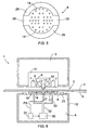
- Figure 3 schematically illustrates a top view of the measuring head of Figure 2;
- Figure 4 schematically illustrates a side view and a cross-section of the measuring head of a second measuring device according to the invention
- Figure 5 schematically illustrates a bottom view of the reference part of the measuring head according to Figure 4.
- Figure 6 schematically illustrates a side view and a cross-section of a third measuring device according to the invention.
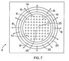
- Figure 7 schematically illustrates the measuring head of a fourth measuring device according to the invention, seen from the direction of the web.
- Figure 1 shows schematically a cross-section of a measuring device 1 according to the invention, which is in the figure arranged to measure the thickness of a paper web 2 moving in the direction of an arrow A.
- the measuring device 1 comprises a first measuring head 3 and a second measuring head 4, between which there is an air gap 5 where the paper web 2 moves at a high speed.
- the first measuring head 3 and the second measuring head 4 are arranged in measuring carriages moving in the measuring frame extending over the whole width of the paper web 2 in such a way that the first measuring head 3 and the second measuring head 4 move forwards and backwards, in other words traverse, over the whole width of the web to be produced, whereby the measuring device 1 measures the thickness of the paper web 2 substantially continuously.
- the measuring frame and the measuring carriages are not shown in Figure 1.
- the first measuring head 3 and the second measuring head 4 can also be fixedly arranged in connection with the paper machine, whereby they measure the thickness of the paper web 2 only at one point in the cross-direction of the paper web 2.
- measuring means based on both electromagnetism and optics arranged in connection with the first measuring head 3 and a reference part 6 arranged in connection with the second measuring head 4, against which reference part the paper web 2 is supported and which reference part simultaneously forms a reference surface for measurement.
- the reference part 6 is plate-like, as shown in Figure 1, but the appearance of the reference part 6 can also vary.
- the measuring means based on electromagnetism can be for instance a coil 7, which is shown in a very schematic manner in Figure 1.
- the reference part 6, in turn, is made of a material that conducts electricity well, for instance of steel, aluminium or copper, whereby the distance between the coil 7 and the reference part 6 can be determined in a manner known per se to a person skilled in the art.
- the reference part 6 can also be merely coated with a material that conducts electricity well, whereby the reference part 6 can be made of a large variety of different materials.
- the measuring means based on optics can be for instance a laser 8 comprising a transmitter part 9 for transmitting a measuring beam 11 towards the paper web 2 and a receiver part 10 for receiving a measuring beam 11' reflected from the surface of the paper web 2.
- the measuring means based on electromagnetism determine the distance between the first measuring head 3 and the second measuring head 4, and the measuring means based on optics determine the distance between the first measuring head 3 and the paper web 2, whereby the thickness of the paper web 2 can be determined by subtracting the distance between the first measuring head 3 and the paper web 2 from the distance between the measuring heads 3 and 4.
- the coils 7 and the laser 8 are both arranged in the support element 12, which is fixedly arranged in connection with the first measuring head 3.
- the measuring head 1 comprises control means for controlling the operation of the coils 7 and the laser 8, and an analysing apparatus for processing the measurement information of the coils 7 and the laser 8, the control means and the analysing apparatus not being shown in Figure 1 for the sake of clarity.
- Figure 2 shows a side view and a cross-section of the second measuring head 4, and, compared with Figure 1, enlarged, Figure 3 showing schematically a top view of the second measuring head 4, in other words seen from the direction of the paper web 2.
- the reference part 6, the upper surface of which forms the reference surface 13 for measuring the thickness of the paper web 2, is provided with several holes 14 extending through the reference part 6.
- the reference part 6 is supported against a frame structure 15 of the second measuring head with one or more support elements 16 in such a way that there remains an open air space 17 below the reference part 6.
- the measuring head 4 comprises a feed channel 18, a flow channel 19 and a nozzle opening 20 for supplying a pressurized gaseous medium between the second measuring head 4 and the paper web 2, and means, for example a blower 21 and a blower control unit 22 used to control it, for supplying gas into the feed channel 18.
- Figure 1 does not show valves used in the supply of gas.
- the gas to be supplied is preferably air but it can also be other gas.
- the gas to be supplied into the feed channel 18 flows from the feed channel 18 to the nozzle opening 20 via the flow channel 19.
- the flow channel 19 is annular, as is the nozzle opening 20.
- the nozzle opening 20 is surrounded by a curved control surface 24, whereby the nozzle opening 20 and the curved control surface 24 form some type of a Coanda nozzle.
- the gas is discharged towards the paper web 2, and the curved control surface 24 positioned in the immediate vicinity of the nozzle opening 20 turns the gas flow to the space between the paper web 2 and the second measuring head 4.
- the gas flows in accordance with arrows B.
- the pressure of the gas and thus its flow rate is arranged to be so high that the gas flow provides negative pressure between the paper web 2 and the second measuring head 4, which negative pressure draws the paper web 2 towards the second measuring head 4.
- the negative pressure generated by the effect of the Coanda nozzle affects the air space 17 and further between the reference surface 13 and the paper web 2 at the point of the reference part 6 via the holes 14 formed through the reference part 6 in such a way that the paper web 2 is supported against the upper surface of the reference part 6, i.e. the reference surface 13, due to the effect of the negative pressure.
- the curved control surface 24 can be formed in the frame structure 15 of the second measuring head 4 surrounding the nozzle opening 20 or in a form element 23 arranged around the nozzle opening 20, as shown in the figures.
- the holes 14 formed through the reference part 6 are positioned in the reference part 6 in such a way that the moving paper web 2 places itself straight and even against the measuring region 25 on the measuring surface 13.
- the measuring region 25 is the area where the distance between the first measuring head 3 and the moving paper web 2 is measured for instance by means of the measuring beam 11 of the laser 8 described above.
- the diameter of the measuring region 25 is preferably about 2 mm, but it can also vary.
- the hole pattern formed by the holes 14 in the reference part 6 can also vary in a plurality of ways. In the solutions of the figures, the holes 14 are positioned at different distances in the direction of the web level, i.e. both closer to and further away from the measuring region 25, and in different directions from the measuring region 25.
- the holes 14 are dimensioned in such a way that they are sufficiently great to allow dust or other impurities carried along the paper web 2 to pass through but sufficiently small so that the paper web 2 supported against the reference surface 13 does not blister or crease, but that it places itself evenly against the reference surface 13 and particularly the measuring region 25.
- the hole pattern formed in the reference part 6 can be implemented in such a way that there remains for induction measurement at least one such measuring surface 26 on the reference surface 13 that does not contain holes 14.
- the reference part 6 comprises four measuring surfaces 26, and by arranging at the first measuring head 3 four coils 7 or four other measuring means based on electromagnetism against the measuring surfaces 26 at corresponding points it becomes possible to compensate changes in the position between the reference plate 6 and the first measuring head 3 or the support element 12 away from the measurement.
- the distance between the reference surface 13 of the reference part 6 and the first measuring part 3 as many coils 7 as is suitable for each particular case are used, for instance only one coil 7, whereby the measuring region 25 can preferably be used as the measuring surface 26.
- the moving paper web 2 can be supported against the reference surface 13 in such a way that the vibrations generated in the web cannot detach the web from the reference surface 13 in the measuring region 25.
- the web cannot blister or crease in other ways either, but it stays supported against the reference surface 13 in the area of the measuring region 25, whereby the measurement easily achieves the measuring accuracy of below one micrometer.
- the accuracy of the measurement can be further improved by compensating the position changes between the first measuring head 3 and the reference surface 6 away from the measurement results.
- the same end result is achieved by measuring the distance between the first measuring head 3 and the reference surface 13 at the point of the measuring region 25.
- the size of the cross-section of the holes 14 in such a way that dust or other impurities carried along the paper web 2 can pass, due to the effect of the negative pressure, through the holes 14 to the air space 17 below the reference part 6, and further to the space between the paper web 2 and the second measuring head 4, and still further out of the measuring device 1 along the web, preventing thus the second measuring head 4 from getting dirty, whereby the cleaning measures directed at the second measuring head 4 can be omitted as being unnecessary, or at least, the interval between the cleaning measures can be made longer.
- the feed pressure of the gas to be supplied between the moving paper web 2 and the second measuring head 4 can vary depending for example on the speed, tension, type and basis weight of the paper web 2.
- the flow rate of the gas can be changed by means of a blower 21, for instance, which is guided with a blower control unit 22.
- a negative-pressure sensor 27 that measures the negative pressure prevailing in the air space 17 can also be arranged in the air space 17, which sensor gives measurement information PA on the negative pressure, by means of which information the blower control unit 22 can control the operation of the blower 21.
- the pressure difference that has to be formed between the reference surface 13 and the air space 17 to support the paper web 2 against the reference surface 13 is very small.
- the pressure difference typically varies between 1 to 20%, but it can also be smaller or greater. The smaller the pressure difference, the less dust carried along the web goes through the holes 14.
- Figures 4 and 5 show a second embodiment of the second measuring device 1, Figure 4 illustrating a side view and a cross-section of the second measuring head 4 and Figure 5 illustrating a bottom view of the reference part 6.
- elevations 28 On the lower surface of the reference part 6, at the edges thereof, elevations 28 have been formed in such a way that two air channels 29 remain between the elevations 28 in the direction of travel of the paper web 2.
- the elevations 28 prevent the gaseous medium from flowing to the space between the paper web 2 and the second measuring head 4 from somewhere else than through the air channels 29 in the way shown by arrows B.
- the amount of gas to be supplied to the space between the paper web 2 and the second measuring head 4 can be reduced, achieving at the same time sufficient negative pressure between the reference surface 13 and the paper web 2 through the holes 14 to support the web smoothly against the reference surface 13.
- FIG. 6 schematically shows a side view and a cross-section of a third measuring device 1 according to the invention.
- the measuring device 1 of Figure 6 comprises a vacuum pump 30 with a control unit 31, by means of which negative pressure can be generated in the air space 17 via channels 32 and 33 and further between the reference surface 13 and the paper web 2 through the holes 14 of the reference part 6 in such a way that the paper web 2 is supported against the reference surface 13 at least over the area of the measuring region 25 on the reference surface 13.
- Figure 7 schematically illustrates the second measuring head 4 of a fourth measuring device 1 according to the invention, seen from the direction of the web.
- the second measuring head 4 according to Figure 7 holes 14 are formed in the reference part 6 in such a way that the holes 14 form in the reference part 6 a hole pattern that extends substantially evenly in the direction of the web level, the holes 14 being positioned at substantially the same distances from each other in the hole pattern.
- the measuring region 25 can be any area between the holes 14, whereby the distance between the first measuring head 3 and the moving web 2 can be measured at the point in question, for example by means of the measuring beam 11 of the laser 8 described above.
- the position changes between the reference part 6 and the first measuring head 3 or support element 12 can be compensated for in the manner described earlier, although the reference part 6 comprises no special measuring areas without holes 14.
- the hole pattern of Figure 7 which extends evenly in the direction of the web level, eliminates measuring interferences relating to induction measuring better than for instance the hole pattern of Figure 3, where the reference part 6 comprises special measuring surfaces 26 without holes.
- the reference part 6 is annular, and the nozzle opening 20 is arranged to extend around the whole reference part 6.
- the appearance of the reference part 6 can vary, in other words it may be for instance of the shape of a square or a rectangle. Irrespective of the appearance of the reference part 6, the nozzle opening 20 can be arranged either partly or as a whole to surround the reference part 6.
- the reference part 6 can also be arranged at the first measuring head 3, instead of at the second measuring head 4, in which case measuring means required for the measurement of the web thickness can be arranged at the second measuring head 4.
- the solution according to the invention can also be used in measuring devices that measure other properties of the web, in which devices it is preferable to support the web against the reference surface to achieve an accurate measurement result.
- properties include the colour, gloss or roughness of the web.
- the measuring device has only one measuring head, which comprises both a reference part and measuring means that measure a property of the web, whereby the measuring means are arranged to measure properties of the web supported against the reference surface of the reference part through measuring openings formed through the reference part; thus, also the measuring region 25 could be implemented as a measuring opening.
- a measuring device of this type could be used for instance to optically measure the moisture of a moving web.
- the reference surface 13 can also be formed directly for instance on the side of the moving web in the frame structure 15 of the second measuring head 4.
- a vacuum pump 31 when used, several channels 33 could be arranged, modifying the embodiment of Figure 6, directly in the holes formed through the reference surface 13, in which case an open space 17 below the reference surface 13 would not be necessary either.
- the moving web can be a web of a different type, such as a plastic-film or a textile web.
- the measuring device comprises at least one measuring head (3, 4) having a reference part (6), which comprises a reference surface (13) against which the moving web is supported.
- the reference surface (13) comprises a measuring area (25) in the inside of which the property of the web is measured.
- the reference part (6) is arranged in connection with the measuring head (3, 4) in such a way that below the reference part (6), there is a substantially open air space (17).
- the measuring head (3, 4) comprises means for generating negative pressure in the air space (17) below the reference part (6), and the reference part (6) comprises holes (14) formed through it, in such a way that the negative pressure generated in the air space (17) affects through the reference part (6) the space between the reference surface (13) and the moving web in such a way that the web is supported against the reference surface (13) substantially over the whole area of the measuring area (25).
Landscapes
- Physics & Mathematics (AREA)
- General Physics & Mathematics (AREA)
- Measuring Arrangements Characterized By The Use Of Fluids (AREA)
- Length Measuring Devices By Optical Means (AREA)
- Length Measuring Devices With Unspecified Measuring Means (AREA)
- Paper (AREA)
- Treatment Of Fiber Materials (AREA)
- Belt Conveyors (AREA)
Abstract
Description
- The invention relates to a method of measuring at least one property of a moving web, in which method the property of the moving web is measured by means of a measuring device having at least one measuring head with a reference part, the reference part having a reference surface against which the moving web is supported to measure the property of the web.
- Further, the invention relates to a measuring device for measuring at least one property of a moving web, the measuring device having at least one measuring head with a reference part, the reference part having a reference surface against which the moving web is arranged to be supported to measure the property of the web.
- In paper manufacture, quality properties of paper, such as the thickness of the paper or another property, are typically measured in a continuous manner when a paper web is moving in a paper machine. Usually, measurement of the quality properties of paper is performed by what are called traversing measuring devices, in which the actual measuring detectors or sensors are arranged at measuring heads on the opposite sides of the paper web, the measuring heads, in turn, being arranged in measuring carriages travelling in the cross direction of the paper web over the whole width of the paper web. There is a narrow slot, i.e. an air gap, between the measuring carriages, where the paper web travels at high speed. The measuring devices can, however, be positioned fixedly, whereby they measure the same point in the cross direction of the paper web all the time.
- In modern paper manufacture, there are very high requirements for measuring methods of the thickness of paper, in particular. For example, the thickness of the web manufactured with a newsprint machine is typically about 70 µm, and the external measuring accuracy that is the aim of the measurement is below 1 µm. The measuring accuracy to be aimed at may even be 0.3 µm. Techniques used for measuring the thickness of paper are typically based on utilization of electromagnetism, optics or a combination thereof. In measuring devices utilizing optics, it is very important to keep the paper as straight and even as possible during the measurement; the aim is to guarantee this by bringing the web to the immediate vicinity of the measuring head, or even into contact with the measuring head, in which case the surface of the measuring head or a reference part arranged therein, being in contact with the web, forms the reference surface for the measurement. However, present solutions have the problem of the web vibrating at high frequencies when the paper moves forwards at a high speed, which vibration proceeds in the web to the measuring point of the thickness of the web, so that the web does not stay in contact with the reference surface at the measuring point, which leads to inaccurate measurement.
- Fl publication 973 448 discloses a measuring device based on electromagnetism, used for measurement of the thickness of a moving matter, such as a paper web, the device comprising a sliding panel against which the moving matter is supported for the measurement. There is/are one or more grooves machined as far as to the edge of the sliding panel in the direction of travel of the moving matter on the surface of the sliding panel. The grooves are machined in such a way that the width of the grooves increases as one moves towards the edge of the sliding panel. Further, there are channels machined on the sliding panel which supply pressurized air to the grooves from their narrower end, whereby negative pressure is generated between the sliding panel and the moving matter due to the effect of the pressurized air and the grooves, which negative pressure draws the moving matter against the sliding panel. The thickness of the moving matter can be determined by means of the distance between a measuring coil arranged on the sliding panel and a measuring probe arranged on the opposite side of the web relative to the measuring coil and the sliding panel. The problem in the solution disclosed in the publication is that when the moving matter is a thin paper web, for instance, the web easily vibrates when moving at a high speed, and blisters and bends due to the effect of the negative pressure in the grooves, whereby the web is easily lifted up from the reference surface formed by the sliding panel, and thus the measuring accuracy of the measuring device is weakened.
-
DE publication 19 913 928 discloses a measuring device for determining properties of a moving web and particularly the thickness of a moving paper web. The measuring device comprises an upper part arranged above the web, which upper part is kept at a distance from the upper surface of the web in such a way that it does not touch the web. Further, the measuring device comprises a lower part arranged below the web, which lower part is kept in contact with the lower surface of the web by means of the suction effect created by the design of the upper surface of the lower part and by the airflows caused by the air carried along the moving web, and possibly in addition, by means of special support means. The lower part of the measuring device can be brought in contact with the web also thanks to blow and suction effects directed at the web. According to an embodiment of the measuring device disclosed in the publication, the upper part of the measuring device comprises measuring means based on electromagnetism and optics for determining the distance between the upper and the lower parts of the measuring device and the distance between the upper part of the measuring device and the upper surface of the web and thus for determining the thickness of the web. In the solution disclosed in the publication, using air carried along the web to guarantee the contact between the lower part of the measuring device and the web is problematic, for example when the speed of travel of the moving web varies. Further, blisters may be formed in the moving web due to the design of the upper surface of the lower part of the measuring device and the effect of the negative pressure generated by the air carried along the web in such a way that the web can at some points be lifted up from the reference surface formed by the lower part of the measuring device, which weakens the measuring accuracy of the measuring device. - An object of the present invention is to provide a new type of solution to support a moving web against a reference part in a measuring device. A device and method for measuring a web of paper, as described in the preamble of
claim - A method according to the invention is characterized by the reference surface comprising a measuring region, from the inside of which measuring region the property of the web is measured, and negative pressure being generated between the moving web and the reference surface through the reference part in such a way that the negative pressure affects the moving web in the direction of the web level at different distances from the measuring region in such a way that due to the effect of the negative pressure, the moving web is supported against the reference surface substantially over the whole area of the measuring region.
- Further, the measuring device according to the invention is characterized in that the reference surface comprises a measuring region, from the inside of which measuring region the property of the web is arranged to be measured, and that the reference part is arranged in connection with the measuring head in such a way that below the reference part, there is a substantially open air space, and that the measuring head comprises means for generating negative pressure in the air space below the reference part, and that the reference part comprises holes formed through it at different distances from the measuring region in such a way that the negative pressure to be generated in the air space is arranged to affect, through the holes formed through the reference part, between the reference surface and the moving web in such a way that due to the effect of the negative pressure, the moving web is supported against the reference surface substantially over the whole area of the measuring region
- According to an essential idea of the invention, at least one property of the moving web is measured by means of a measuring device having at least one measuring head with a reference part, the reference part having a reference surface against which the moving web is supported to measure the property of the web. Further, according to an essential idea, the reference surface comprises a measuring region, from the inside of which measuring region the property of the web is measured, and that negative pressure is generated through the reference part between the moving web and the reference surface in such a way that due to the effect of the negative pressure, the moving web is supported against the reference surface substantially over the whole area of the measuring region. According to a preferred embodiment of the invention, the reference part is arranged in connection with the measuring head in such a way that below the reference part, there is a substantially open air space, and that the measuring head comprises means for generating negative pressure in the air space below the reference part, and that the reference part comprises holes formed through it, in such a way that the negative pressure to be generated in the air space is arranged to affect between the reference surface and the moving web through the holes formed through the reference part in such a way that due to the effect of the negative pressure, the moving web is supported against the reference surface substantially over the whole area of the measuring region According to a second preferred embodiment of the invention, the measuring head comprises at least one channel that is in connection with the open air space below the reference part, whereby the negative pressure is generated in the air space by supplying a gaseous medium between the measuring head and the moving web. According to a third preferred embodiment of the invention, the lower surface of the reference part comprises two air channels substantially parallel relative to the direction of travel of the moving web for supplying a gaseous medium between the measuring head and the moving web substantially in parallel with the direction of travel of the moving web. According to a fourth preferred embodiment of the invention, the negative pressure between the reference surface and the moving web is arranged to be somewhat below the ambient pressure, typically 80 to 99% of the ambient pressure. According to a fifth preferred embodiment of the invention, the measuring device comprises a first measuring head and a second measuring head, between which there is an air gap where the moving web is arranged to travel, the reference part being arranged at the second measuring head. According to a sixth preferred embodiment of the invention, the first measuring head comprises both at least one electromagnetic measuring means for determining the distance between the first measuring head and the reference part at the second measuring head and at least one optical measuring means for determining the distance between the first measuring head and the web supported against the reference surface.
- By means of the solution according to the invention, the moving web can be supported against the measuring region on the reference surface of the reference part in such a way that the web stays supported against the reference surface in the measuring region despite vibrations generated while it moves, owing to which the property of the web can be measured very accurately. When the reference part is arranged in connection with the measuring head in such a way that there is a substantially open air gap below the reference part, and when holes extending through the reference part have been formed in the reference part, it is easy to generate negative pressure between the web and the reference surface by means of the negative pressure generated in the air gap. By supplying a gaseous medium between the web and the measuring head from a channel that is in connection with the air gap below the reference part, negative pressure can be generated in the air gap in a simple and easy manner. When a gaseous medium is supplied to the space between the measuring head and the moving web only in parallel with the direction of travel of the moving web, only a small amount of gas is required to provide sufficient negative pressure between the web and the reference surface. When the measuring device comprises a first measuring head and a second measuring head between which there is an air gap in which the moving web travels, and when the first measuring head comprises means for determining the distance between the first measuring head and the reference part arranged at the second reference head and means for determining the distance between the first measuring head and the web supported against the reference surface, it is easy to measure the thickness of the moving web at the accuracy of less than one micrometer.
- In the present description, the term 'paper' refers, in addition to paper, also to board, tissue and pulp.
- The invention will be explained in more detail in the attached drawings, of which
- Figure 1 schematically illustrates a side view and a cross-section of a measuring device according to the invention;
- Figure 2 schematically illustrates a side view and a cross-section of the measuring head of the measuring device of Figure 1;
- Figure 3 schematically illustrates a top view of the measuring head of Figure 2;
- Figure 4 schematically illustrates a side view and a cross-section of the measuring head of a second measuring device according to the invention;
- Figure 5 schematically illustrates a bottom view of the reference part of the measuring head according to Figure 4; and
- Figure 6 schematically illustrates a side view and a cross-section of a third measuring device according to the invention; and
- Figure 7 schematically illustrates the measuring head of a fourth measuring device according to the invention, seen from the direction of the web.
- Figure 1 shows schematically a cross-section of a
measuring device 1 according to the invention, which is in the figure arranged to measure the thickness of apaper web 2 moving in the direction of an arrow A. For the sake of clarity, thepaper web 2 is in Figure 1 shown as being essentially thicker than it is in reality. Themeasuring device 1 comprises afirst measuring head 3 and a second measuringhead 4, between which there is anair gap 5 where thepaper web 2 moves at a high speed. Typically, the first measuringhead 3 and the second measuringhead 4 are arranged in measuring carriages moving in the measuring frame extending over the whole width of thepaper web 2 in such a way that the first measuringhead 3 and the second measuringhead 4 move forwards and backwards, in other words traverse, over the whole width of the web to be produced, whereby themeasuring device 1 measures the thickness of thepaper web 2 substantially continuously. For the sake of clarity, the measuring frame and the measuring carriages are not shown in Figure 1. The first measuringhead 3 and the second measuringhead 4 can also be fixedly arranged in connection with the paper machine, whereby they measure the thickness of thepaper web 2 only at one point in the cross-direction of thepaper web 2. - In order to measure the thickness of the
paper web 2, there are measuring means based on both electromagnetism and optics arranged in connection with the first measuringhead 3 and areference part 6 arranged in connection with the second measuringhead 4, against which reference part thepaper web 2 is supported and which reference part simultaneously forms a reference surface for measurement. Preferably, thereference part 6 is plate-like, as shown in Figure 1, but the appearance of thereference part 6 can also vary. The measuring means based on electromagnetism can be for instance acoil 7, which is shown in a very schematic manner in Figure 1. Thereference part 6, in turn, is made of a material that conducts electricity well, for instance of steel, aluminium or copper, whereby the distance between thecoil 7 and thereference part 6 can be determined in a manner known per se to a person skilled in the art. Thereference part 6 can also be merely coated with a material that conducts electricity well, whereby thereference part 6 can be made of a large variety of different materials. The measuring means based on optics can be for instance alaser 8 comprising atransmitter part 9 for transmitting ameasuring beam 11 towards thepaper web 2 and areceiver part 10 for receiving a measuring beam 11' reflected from the surface of thepaper web 2. The measuring means based on electromagnetism determine the distance between the first measuringhead 3 and the second measuringhead 4, and the measuring means based on optics determine the distance between the first measuringhead 3 and thepaper web 2, whereby the thickness of thepaper web 2 can be determined by subtracting the distance between the first measuringhead 3 and thepaper web 2 from the distance between themeasuring heads coils 7 and thelaser 8 are both arranged in thesupport element 12, which is fixedly arranged in connection with the first measuringhead 3. Further, themeasuring head 1 comprises control means for controlling the operation of thecoils 7 and thelaser 8, and an analysing apparatus for processing the measurement information of thecoils 7 and thelaser 8, the control means and the analysing apparatus not being shown in Figure 1 for the sake of clarity. - In measuring devices utilizing optics for measuring the thickness of a moving web, it is very important to keep the moving web at the measuring moment as straight and even as possible; the aim is to guarantee this by supporting the moving web against the reference surface in the measuring device. When the web moves forwards at a high speed, highfrequency vibrations are generated in the web, which vibrations proceed in the web and tend to detach the web from the reference surface, whereby the measuring accuracy is weakened.
- In the measuring device according to Figure 1, this drawback has been corrected in a way shown in more detail in Figures 2 and 3. Figure 2 shows a side view and a cross-section of the
second measuring head 4, and, compared with Figure 1, enlarged, Figure 3 showing schematically a top view of thesecond measuring head 4, in other words seen from the direction of thepaper web 2. Thereference part 6, the upper surface of which forms thereference surface 13 for measuring the thickness of thepaper web 2, is provided withseveral holes 14 extending through thereference part 6. Thereference part 6 is supported against aframe structure 15 of the second measuring head with one ormore support elements 16 in such a way that there remains anopen air space 17 below thereference part 6. Further, the measuringhead 4 comprises afeed channel 18, aflow channel 19 and anozzle opening 20 for supplying a pressurized gaseous medium between thesecond measuring head 4 and thepaper web 2, and means, for example a blower 21 and ablower control unit 22 used to control it, for supplying gas into thefeed channel 18. For the sake of clarity, Figure 1 does not show valves used in the supply of gas. The gas to be supplied is preferably air but it can also be other gas. The gas to be supplied into thefeed channel 18 flows from thefeed channel 18 to thenozzle opening 20 via theflow channel 19. In the embodiment according to Figure 1, theflow channel 19 is annular, as is thenozzle opening 20. Thenozzle opening 20 is surrounded by acurved control surface 24, whereby thenozzle opening 20 and thecurved control surface 24 form some type of a Coanda nozzle. From thenozzle opening 20, the gas is discharged towards thepaper web 2, and thecurved control surface 24 positioned in the immediate vicinity of thenozzle opening 20 turns the gas flow to the space between thepaper web 2 and thesecond measuring head 4. Thus, the gas flows in accordance with arrows B. The pressure of the gas and thus its flow rate is arranged to be so high that the gas flow provides negative pressure between thepaper web 2 and thesecond measuring head 4, which negative pressure draws thepaper web 2 towards thesecond measuring head 4. The negative pressure generated by the effect of the Coanda nozzle affects theair space 17 and further between thereference surface 13 and thepaper web 2 at the point of thereference part 6 via theholes 14 formed through thereference part 6 in such a way that thepaper web 2 is supported against the upper surface of thereference part 6, i.e. thereference surface 13, due to the effect of the negative pressure. Thecurved control surface 24 can be formed in theframe structure 15 of thesecond measuring head 4 surrounding thenozzle opening 20 or in aform element 23 arranged around thenozzle opening 20, as shown in the figures. - The
holes 14 formed through thereference part 6 are positioned in thereference part 6 in such a way that the movingpaper web 2 places itself straight and even against the measuringregion 25 on the measuringsurface 13. The measuringregion 25 is the area where the distance between thefirst measuring head 3 and the movingpaper web 2 is measured for instance by means of themeasuring beam 11 of thelaser 8 described above. The diameter of the measuringregion 25 is preferably about 2 mm, but it can also vary. The hole pattern formed by theholes 14 in thereference part 6 can also vary in a plurality of ways. In the solutions of the figures, theholes 14 are positioned at different distances in the direction of the web level, i.e. both closer to and further away from the measuringregion 25, and in different directions from the measuringregion 25. In the direction of travel of the web, there areholes 14 both before the measuringregion 25 and after the measuringregion 25. Also in the cross-direction of the web, there areholes 14 on both sides of the measuringregion 25. When theholes 14 of thereference part 6 are positioned in said manner, the moving paper web places itself in a very straight and even manner against thereference surface 13 and particularly the measuringregion 25. The proportion of he open portion of thereference surface 13 formed by the holes to the closed portion can vary, as can the size of the cross-section of the holes. Theholes 14 are dimensioned in such a way that they are sufficiently great to allow dust or other impurities carried along thepaper web 2 to pass through but sufficiently small so that thepaper web 2 supported against thereference surface 13 does not blister or crease, but that it places itself evenly against thereference surface 13 and particularly the measuringregion 25. The hole pattern formed in thereference part 6 can be implemented in such a way that there remains for induction measurement at least onesuch measuring surface 26 on thereference surface 13 that does not contain holes 14. In the case of Figure 3, thereference part 6 comprises four measuringsurfaces 26, and by arranging at thefirst measuring head 3 fourcoils 7 or four other measuring means based on electromagnetism against the measuring surfaces 26 at corresponding points it becomes possible to compensate changes in the position between thereference plate 6 and thefirst measuring head 3 or thesupport element 12 away from the measurement. Naturally, it is obvious that for determination of the distance between thereference surface 13 of thereference part 6 and the first measuringpart 3, asmany coils 7 as is suitable for each particular case are used, for instance only onecoil 7, whereby the measuringregion 25 can preferably be used as the measuringsurface 26. - By means of the present solution, the moving
paper web 2 can be supported against thereference surface 13 in such a way that the vibrations generated in the web cannot detach the web from thereference surface 13 in the measuringregion 25. The web cannot blister or crease in other ways either, but it stays supported against thereference surface 13 in the area of the measuringregion 25, whereby the measurement easily achieves the measuring accuracy of below one micrometer. By forming four such measuring surfaces 26 on thereference surface 13 where there are no holes, and by providing thefirst measuring head 3 with fourcoils 7, the accuracy of the measurement can be further improved by compensating the position changes between thefirst measuring head 3 and thereference surface 6 away from the measurement results. However, the same end result is achieved by measuring the distance between thefirst measuring head 3 and thereference surface 13 at the point of the measuringregion 25. Further, by selecting the size of the cross-section of theholes 14 in such a way that dust or other impurities carried along thepaper web 2 can pass, due to the effect of the negative pressure, through theholes 14 to theair space 17 below thereference part 6, and further to the space between thepaper web 2 and thesecond measuring head 4, and still further out of the measuringdevice 1 along the web, preventing thus thesecond measuring head 4 from getting dirty, whereby the cleaning measures directed at thesecond measuring head 4 can be omitted as being unnecessary, or at least, the interval between the cleaning measures can be made longer. - The feed pressure of the gas to be supplied between the moving
paper web 2 and thesecond measuring head 4 can vary depending for example on the speed, tension, type and basis weight of thepaper web 2. The flow rate of the gas can be changed by means of a blower 21, for instance, which is guided with ablower control unit 22. A negative-pressure sensor 27 that measures the negative pressure prevailing in theair space 17 can also be arranged in theair space 17, which sensor gives measurement information PA on the negative pressure, by means of which information theblower control unit 22 can control the operation of the blower 21. The pressure difference that has to be formed between thereference surface 13 and theair space 17 to support thepaper web 2 against thereference surface 13 is very small. Even the pressure that is about one per cent smaller in theair space 17 compared with the pressure between thereference surface 13 and thepaper web 2 is sufficient to support the web against thereference surface 13 without vibration or blistering. Depending on the speed, basis weight, type and tension of thepaper web 2, the pressure difference typically varies between 1 to 20%, but it can also be smaller or greater. The smaller the pressure difference, the less dust carried along the web goes through theholes 14. - Figures 4 and 5 show a second embodiment of the
second measuring device 1, Figure 4 illustrating a side view and a cross-section of thesecond measuring head 4 and Figure 5 illustrating a bottom view of thereference part 6. On the lower surface of thereference part 6, at the edges thereof,elevations 28 have been formed in such a way that twoair channels 29 remain between theelevations 28 in the direction of travel of thepaper web 2. When thereference part 6 is positioned in its place at thesecond measuring head 4, theelevations 28 prevent the gaseous medium from flowing to the space between thepaper web 2 and thesecond measuring head 4 from somewhere else than through theair channels 29 in the way shown by arrows B. By means of this solution, the amount of gas to be supplied to the space between thepaper web 2 and thesecond measuring head 4 can be reduced, achieving at the same time sufficient negative pressure between thereference surface 13 and thepaper web 2 through theholes 14 to support the web smoothly against thereference surface 13. - Figure 6 schematically shows a side view and a cross-section of a
third measuring device 1 according to the invention. The measuringdevice 1 of Figure 6 comprises avacuum pump 30 with a control unit 31, by means of which negative pressure can be generated in theair space 17 viachannels reference surface 13 and thepaper web 2 through theholes 14 of thereference part 6 in such a way that thepaper web 2 is supported against thereference surface 13 at least over the area of the measuringregion 25 on thereference surface 13. - Figure 7 schematically illustrates the
second measuring head 4 of afourth measuring device 1 according to the invention, seen from the direction of the web. In thesecond measuring head 4 according to Figure 7, holes 14 are formed in thereference part 6 in such a way that theholes 14 form in the reference part 6 a hole pattern that extends substantially evenly in the direction of the web level, theholes 14 being positioned at substantially the same distances from each other in the hole pattern. In connection with thereference part 6 shown in Figure 7, the measuringregion 25 can be any area between theholes 14, whereby the distance between thefirst measuring head 3 and the movingweb 2 can be measured at the point in question, for example by means of themeasuring beam 11 of thelaser 8 described above. The position changes between thereference part 6 and thefirst measuring head 3 orsupport element 12 can be compensated for in the manner described earlier, although thereference part 6 comprises no special measuring areas without holes 14. In some cases, it has been observed that the hole pattern of Figure 7, which extends evenly in the direction of the web level, eliminates measuring interferences relating to induction measuring better than for instance the hole pattern of Figure 3, where thereference part 6 comprises special measuring surfaces 26 without holes. - The drawings and the related description are only intended to illustrate the idea of the invention. The details of the invention may vary within the scope of the claims. In Figures 1 to 6, the
reference part 6 is annular, and thenozzle opening 20 is arranged to extend around thewhole reference part 6. However, the appearance of thereference part 6 can vary, in other words it may be for instance of the shape of a square or a rectangle. Irrespective of the appearance of thereference part 6, thenozzle opening 20 can be arranged either partly or as a whole to surround thereference part 6. Thereference part 6 can also be arranged at thefirst measuring head 3, instead of at thesecond measuring head 4, in which case measuring means required for the measurement of the web thickness can be arranged at thesecond measuring head 4. Further, the solution according to the invention can also be used in measuring devices that measure other properties of the web, in which devices it is preferable to support the web against the reference surface to achieve an accurate measurement result. Such properties include the colour, gloss or roughness of the web. Further, it may be the case that the measuring device has only one measuring head, which comprises both a reference part and measuring means that measure a property of the web, whereby the measuring means are arranged to measure properties of the web supported against the reference surface of the reference part through measuring openings formed through the reference part; thus, also the measuringregion 25 could be implemented as a measuring opening. A measuring device of this type could be used for instance to optically measure the moisture of a moving web. Further, aspecial reference part 6 is not necessary, but thereference surface 13 can also be formed directly for instance on the side of the moving web in theframe structure 15 of thesecond measuring head 4. In this case, when a vacuum pump 31 is used,several channels 33 could be arranged, modifying the embodiment of Figure 6, directly in the holes formed through thereference surface 13, in which case anopen space 17 below thereference surface 13 would not be necessary either. Instead of apaper web 2 or a board, a tissue or a pulp web, the moving web can be a web of a different type, such as a plastic-film or a textile web. - The measuring device comprises at least one measuring head (3, 4) having a reference part (6), which comprises a reference surface (13) against which the moving web is supported. The reference surface (13) comprises a measuring area (25) in the inside of which the property of the web is measured. The reference part (6) is arranged in connection with the measuring head (3, 4) in such a way that below the reference part (6), there is a substantially open air space (17). The measuring head (3, 4) comprises means for generating negative pressure in the air space (17) below the reference part (6), and the reference part (6) comprises holes (14) formed through it, in such a way that the negative pressure generated in the air space (17) affects through the reference part (6) the space between the reference surface (13) and the moving web in such a way that the web is supported against the reference surface (13) substantially over the whole area of the measuring area (25).
Claims (28)
- A method for measuring a property of a moving web by means of a measuring device (1) having a measuring head (4),
wherein the measuring head (4) comprises
a plate-like reference part (6) having a reference surface (13) against which the moving web is to be supported for measuring the property of the web,
a frame structure (15) for supporting the reference part (6), and
a substantially open air space (17) below the reference part (6),
wherein the reference surface (13) comprises a measuring region (25) at which the property of the web is measured, and
wherein the reference part (6) comprises holes (14) formed through it at different distances from the measuring region (25),
wherein the method comprises the steps of
generating a negative pressure in the air space (17) below the reference part (6), and
applying the negative pressure through the holes (14) formed through the reference part (6) to the moving web for generating negative pressure between the moving web and the reference surface (13) so that, due to the effect of the negative pressure, the moving web is supported against the reference surface (13) substantially over the whole area of the measuring region (25),
characterized
in that the measuring head (4) furthermore comprises a nozzle opening (20) formed between the reference part (6) and the frame structure (15) and opening into a space between the frame structure (15) and the moving web, and
at least one channel (19, 29) which is connected to the air space (17) below the reference part (6) and to the nozzle opening (20), and which is arranged to supply a gaseous medium to the nozzle opening (20),
wherein the gaseous medium supplied to the nozzle opening (20) and supplied from the nozzle opening (20) into the space between the frame structure (15) and the moving web generates negative pressure in the space between the frame structure (15) and the moving web and furthermore generates the negative pressure in the air space (17) below the reference part (6). - A method according to claim 1, characterized by generating the negative pressure between the moving web and the reference surface (13) through the holes (14) formed through the reference part (6) in such a way that due to the effect of the negative pressure, the moving web is supported against the reference surface (13) substantially over the whole area of the reference surface (13).
- A method according to claim 1 or 2, characterized in that the flow of the gaseous medium is turned to flow between the frame structure (15) and the moving web by means of a curved control surface (24) surrounding the nozzle opening (20).
- A method according to any one of claims 1 to 3, characterized by the gaseous medium being air.
- A method according to any one of the preceding claims, characterized by measuring the negative pressure in the air space (17) and changing the negative pressure prevailing in the air space (17) on the basis of the measurement information (PA) of the negative pressure in the air space (17).
- A method according to any one of the preceding claims, characterized by the negative pressure between the reference surface (13) and the moving web being 80 to 99% of the pressure of the ambient air.
- A method according to any one of the preceding claims, characterized by measuring optically the property of the moving web.
- A method according to claim 7, characterized by the property of the moving web to be measured being the colour, gloss, roughness or moisture of the moving web.
- A method according to any one of the preceding claims, characterized by arranging the moving web to travel through an air gap (5) between the measuring head (4) comprising the reference part (6) and a second measuring head (3).
- A method according to claim 9, characterized by measuring inductively the distance between the second measuring head (3) and the reference surface (13) of the reference part (6).
- A method according to claim 10, characterized by the measuring device (1) being arranged to measure the thickness of the moving web.
- A method according to any one of the preceding claims, characterized by the moving web being a paper web (2), a board web, a tissue web or a pulp web.
- A measuring device for measuring a property of a moving web, the measuring device (1) having a measuring head (4) which comprises
a plate-like reference part (6) having a reference surface (13) against which the moving web is to be supported for measuring the property of the web,
a frame structure (15) for supporting the reference part (6),
substantially open air space (17) below the reference part (6), and
means (18 to 21, 29) for generating negative pressure in the air space (17) below the reference part (6),
wherein the reference surface (13) comprises a measuring region (25) at which the property of the web is measured, and
wherein the reference part (6) comprises holes (14) formed through it at different distances from the measuring region (25) in such a way that the negative pressure generated in the air space (17) acts between the reference surface (13) and the moving web so that, due to the effect of the negative pressure, the moving web is supported against the reference surface (13) substantially over the whole area of the measuring region (25),
characterized
in that the measuring head (4) furthermore comprises a nozzle opening (20) formed between the reference part (6) and the frame structure (15) and opening into a space between the frame structure (15) and the moving web, and
at least one channel (19, 29) which is connected to the air space (17) below the reference part (6) and to the nozzle opening (20) and which is arranged to supply a gaseous medium to the nozzle opening (20),
wherein the nozzle opening (20) is arranged such that the gaseous medium supplied to it and supplied from it into the space between the frame structure (15) and the moving web generates negative pressure in the space between the frame structure (15) and the moving web and furthermore generates the negative pressure in the air space (17) below the reference part (6). - A measuring device according to claim 13, characterized in that the holes (14) are formed through the reference part (6) in such a way that due to the effect of the negative pressure generated in the air space (17) and acting between the reference surface (13) and the moving web, the moving web is supported against the reference surface (13) substantially over the whole area of the reference surface (13).
- A measuring device according to claim 13 or 14, characterized in that the frame structure (15) comprises a curved control surface (24) surrounding the nozzle opening (20) for turning the flow of the gaseous medium to flow to the space between the frame structure (15) and the moving web.
- A measuring device according to any one of claims 13 to 15, characterized in that two of said channels (29) are provided on the lower surface of the reference part (6) and extend substantially parallel relative to the direction of travel (A) of the web to supply the gaseous medium between the frame structure (15) and the moving web substantially in parallel relative to the direction of travel (A) of the moving web.
- A measuring device according to any one of claims 13 to 16, characterized in that the gaseous medium is air.
- A measuring device according to any one of claims 13 to 17, characterized in that the reference part (6) is made of a material that conducts electricity well.
- A measuring device according to any one of claims 13 to 18, characterized in that a negative-pressure sensor (27) is arranged in the air space (17) below the reference part (6) for measuring the negative pressure prevailing in the air space (17) and that the feed pressure of the gaseous medium is arranged to be changed on the basis of the measurement information (PA) of the negative pressure in the air space (17).
- A measuring device according to any one of claims 13 to 19, characterized in that the negative pressure acting at the reference surface (13) on the moving web is 80 to 99% of the ambient air pressure.
- A measuring device according to any one of claims 13 to 20, characterized in that the measuring device (1) comprises at least one optical measuring means (8) for measuring a variable expressing the property of the moving web.
- A measuring device according to claim 21, characterized in that the measuring means is a laser (8).
- A measuring device according to claim 21 or 22, characterized in that the property of the moving web to be measured is the colour, gloss, roughness or moisture of the moving web.
- A measuring device according to any one of claims 13 to 23, characterized in that it comprises, in addition to the measuring head (4) comprising the reference part (6), a second measuring head (3), wherein an air gap (5) where the moving web is arranged to travel is provided between the two measuring heads (3, 4).
- A measuring device according to claim 24, characterized in that the second measuring head (3) comprises at least one electromagnetic measuring means (7) for determining the distance between the second measuring head (3) and the reference surface (13) of the reference part (6).
- A measuring device according to claim 25, characterized in that the electromagnetic measuring means is a coil (7).
- A measuring device according to claim 25 or 26, characterized in that the measuring device (1) is arranged to measure the thickness of the moving web.
- A measuring device according to any one of claims 13 to 27, characterized in that the moving web is a paper web (2), a board web, a tissue web or a pulp web.
Applications Claiming Priority (2)
| Application Number | Priority Date | Filing Date | Title |
|---|---|---|---|
| FI20011447 | 2001-07-03 | ||
| FI20011447A FI114337B (en) | 2001-07-03 | 2001-07-03 | Method and gauge for measuring at least one property of a moving web |
Publications (3)
| Publication Number | Publication Date |
|---|---|
| EP1273879A2 EP1273879A2 (en) | 2003-01-08 |
| EP1273879A3 EP1273879A3 (en) | 2004-01-02 |
| EP1273879B1 true EP1273879B1 (en) | 2006-08-30 |
Family
ID=8561573
Family Applications (1)
| Application Number | Title | Priority Date | Filing Date |
|---|---|---|---|
| EP02014650A Expired - Lifetime EP1273879B1 (en) | 2001-07-03 | 2002-07-02 | Method and measuring device for measuring at least one property of a moving web |
Country Status (6)
| Country | Link |
|---|---|
| US (1) | US6743338B2 (en) |
| EP (1) | EP1273879B1 (en) |
| AT (1) | ATE338259T1 (en) |
| CA (1) | CA2390198C (en) |
| DE (1) | DE60214287T2 (en) |
| FI (1) | FI114337B (en) |
Families Citing this family (30)
| Publication number | Priority date | Publication date | Assignee | Title |
|---|---|---|---|---|
| DE10343515A1 (en) * | 2003-09-19 | 2005-04-14 | Voith Paper Patent Gmbh | measuring device |
| US7206076B2 (en) * | 2003-11-04 | 2007-04-17 | Lumetrics, Inc. | Thickness measurement of moving webs and seal integrity system using dual interferometer |
| DE10361160A1 (en) * | 2003-12-22 | 2005-07-21 | Voith Paper Patent Gmbh | measuring device |
| DE10361161A1 (en) * | 2003-12-22 | 2005-07-21 | Voith Paper Patent Gmbh | measuring device |
| SE528617C2 (en) * | 2005-05-11 | 2006-12-27 | Elisebergs Teknik & Design Ab | Apparatus, method and machine comprising apparatus for measuring voltage or voltage change in a paper web |
| DE202005017506U1 (en) * | 2005-11-07 | 2007-03-22 | Wangner Gmbh & Co. Kg | Apparatus for inspecting a sheet, e.g. a paper machine clothing |
| FI119260B (en) | 2006-03-10 | 2008-09-15 | Metso Automation Oy | Method for calibrating measuring equipment and measuring equipment |
| US8282781B2 (en) | 2006-12-11 | 2012-10-09 | Honeywell International Inc. | Apparatus and method for stabilization of a moving sheet relative to a sensor |
| WO2009032094A1 (en) * | 2007-08-31 | 2009-03-12 | Abb Ltd. | Web thickness measurement device |
| US9045306B2 (en) * | 2007-11-27 | 2015-06-02 | Abb Ltd. | Sheet stabilizer with suction nozzle having center protrusion |
| US8028988B2 (en) * | 2008-01-21 | 2011-10-04 | Honeywell International Inc. | Apparatus and method for stabilizing a moving sheet relative to a sensor |
| US8088255B2 (en) * | 2008-04-18 | 2012-01-03 | Honeywell Asca Inc | Sheet stabilizer with dual inline machine direction air clamps and backsteps |
| US8083895B2 (en) * | 2008-04-18 | 2011-12-27 | Honeywell Asca Inc. | Sheet stabilization with dual opposing cross direction air clamps |
| US7892399B2 (en) | 2008-05-29 | 2011-02-22 | Honeywell Asca Inc. | Local tension generating air stabilization system for web products |
| US8083896B2 (en) * | 2008-09-26 | 2011-12-27 | Honeywell Asca Inc. | Pressure equalizing baffle and coanda air clamp |
| US9109330B2 (en) * | 2009-03-09 | 2015-08-18 | Honeywell International Inc. | Apparatus and method for measuring properties of unstabilized moving sheets |
| FI20105485A0 (en) * | 2010-05-04 | 2010-05-04 | Metso Automation Oy | Method and arrangement for measuring instrument |
| US9325860B2 (en) | 2010-12-01 | 2016-04-26 | Quadtech, Inc. | Line color monitoring system |
| DE102011107771B4 (en) * | 2011-04-15 | 2013-10-17 | Micro-Epsilon Messtechnik Gmbh & Co. Kg | Device and method for measuring the thickness of a measurement object |
| WO2013026792A1 (en) * | 2011-08-22 | 2013-02-28 | Windmöller & Hölscher Kg | Machine and method for printing webs of material |
| WO2013026791A1 (en) * | 2011-08-22 | 2013-02-28 | Windmöller & Hölscher Kg | Machine and method for printing webs of material |
| US8760669B2 (en) | 2011-09-30 | 2014-06-24 | Honeywell Asca Inc. | Method of measuring the thickness of a moving web |
| KR102023581B1 (en) * | 2012-11-23 | 2019-09-24 | 해성디에스 주식회사 | Reel-to-Reel inspection apparatus and inspection method using the same |
| FI125811B (en) * | 2013-05-29 | 2016-02-29 | Valmet Automation Oy | Track measurement |
| US9007589B2 (en) * | 2013-09-16 | 2015-04-14 | Honeywell Asca Inc. | Co-located porosity and caliper measurement for membranes and other web products |
| CN104457593B (en) * | 2014-11-26 | 2017-02-22 | 北京特种机械研究所 | Device used for measuring thickness of air cushion air film |
| FI126243B (en) * | 2015-01-14 | 2016-08-31 | Takso-Ohjelmistot Oy | Fiber web manipulation device and method |
| US9889995B1 (en) * | 2017-03-15 | 2018-02-13 | Core Flow Ltd. | Noncontact support platform with blockage detection |
| FI20185410A1 (en) * | 2018-05-03 | 2019-11-04 | Valmet Automation Oy | Measurement of elastic modulus of moving web |
| FI128235B (en) * | 2018-12-10 | 2020-01-15 | Procemex Oy Ltd | Top side light |
Family Cites Families (14)
| Publication number | Priority date | Publication date | Assignee | Title |
|---|---|---|---|---|
| US3617872A (en) * | 1969-10-06 | 1971-11-02 | Indev Inc | Magnetic thickness gauge with a gas-supported sensor and a suction source in the base |
| CA919937A (en) * | 1969-11-24 | 1973-01-30 | Consolidated-Bathurst Limited | Paper machine tension tester |
| US3818327A (en) * | 1972-09-05 | 1974-06-18 | Industrial Nucleonics Corp | Measuring gauge with support for holding measured sheet and discharging foreign matter |
| US3855524A (en) * | 1972-09-05 | 1974-12-17 | Industrial Nucleonics Corp | Measuring gauge with air bearing and resistant to tilt |
| US3827808A (en) * | 1973-05-09 | 1974-08-06 | Industrial Nucleonics Corp | Method and apparatus for measuring the opacity of sheet material in which the transmittance signal is compensated for the reflectivity of the material |
| US4246775A (en) * | 1979-06-08 | 1981-01-27 | Philip Morris Incorporated | Porosity measuring apparatus and perforating system using same |
| US4311037A (en) * | 1980-03-19 | 1982-01-19 | Scott Paper Company | Web permeability tester |
| US4449398A (en) * | 1982-06-24 | 1984-05-22 | Accuray Corporation | Sheet property sensor with sheet wrinkle remover |
| US4929895A (en) * | 1989-03-22 | 1990-05-29 | Impact Systems, Inc. | Thickness gauge for moving sheet material with inner and outer flexibly mounted bearings |
| DE19506470C2 (en) * | 1995-02-24 | 1998-07-02 | Honeywell Ag | Slide plate and its use |
| JP2776339B2 (en) * | 1995-10-27 | 1998-07-16 | 横河電機株式会社 | Thickness gauge |
| US6280573B1 (en) * | 1998-08-12 | 2001-08-28 | Kimberly-Clark Worldwide, Inc. | Leakage control system for treatment of moving webs |
| US6281679B1 (en) | 1998-12-21 | 2001-08-28 | Honeywell - Measurex | Web thickness measurement system |
| DE19913928B4 (en) | 1999-03-26 | 2015-06-11 | Voith Patent Gmbh | Device for determining properties of a moving material web |
-
2001
- 2001-07-03 FI FI20011447A patent/FI114337B/en not_active IP Right Cessation
-
2002
- 2002-07-02 US US10/187,584 patent/US6743338B2/en not_active Expired - Lifetime
- 2002-07-02 EP EP02014650A patent/EP1273879B1/en not_active Expired - Lifetime
- 2002-07-02 AT AT02014650T patent/ATE338259T1/en not_active IP Right Cessation
- 2002-07-02 CA CA2390198A patent/CA2390198C/en not_active Expired - Lifetime
- 2002-07-02 DE DE60214287T patent/DE60214287T2/en not_active Expired - Lifetime
Also Published As
| Publication number | Publication date |
|---|---|
| EP1273879A3 (en) | 2004-01-02 |
| EP1273879A2 (en) | 2003-01-08 |
| CA2390198A1 (en) | 2003-01-03 |
| FI20011447A0 (en) | 2001-07-03 |
| DE60214287T2 (en) | 2007-09-13 |
| CA2390198C (en) | 2013-01-08 |
| US20030024301A1 (en) | 2003-02-06 |
| DE60214287D1 (en) | 2006-10-12 |
| US6743338B2 (en) | 2004-06-01 |
| ATE338259T1 (en) | 2006-09-15 |
| FI114337B (en) | 2004-09-30 |
| FI20011447L (en) | 2003-01-04 |
Similar Documents
| Publication | Publication Date | Title |
|---|---|---|
| CA2390198C (en) | Method and measuring device for measuring at least one property of a moving web | |
| FI125343B (en) | Track thickness measuring device | |
| CA2721583C (en) | Sheet stabilization with dual opposing cross direction air clamps | |
| EP2326583B1 (en) | Pressure equalizing baffle and coanda air clamp | |
| US8117891B2 (en) | Method for calibration of measuring equipment and measuring equipment | |
| US7319521B2 (en) | Measuring device | |
| US7892399B2 (en) | Local tension generating air stabilization system for web products | |
| US20130083332A1 (en) | Method of Measuring the Thickness of a Moving Web | |
| EP2262947B1 (en) | Sheet stabilizer with dual inline machine direction air clamps and backsteps | |
| US9045306B2 (en) | Sheet stabilizer with suction nozzle having center protrusion |
Legal Events
| Date | Code | Title | Description |
|---|---|---|---|
| PUAI | Public reference made under article 153(3) epc to a published international application that has entered the european phase |
Free format text: ORIGINAL CODE: 0009012 |
|
| AK | Designated contracting states |
Kind code of ref document: A2 Designated state(s): AT BE BG CH CY CZ DE DK EE ES FI FR GB GR IE IT LI LU MC NL PT SE SK TR |
|
| AX | Request for extension of the european patent |
Free format text: AL;LT;LV;MK;RO;SI |
|
| RIC1 | Information provided on ipc code assigned before grant |
Ipc: 7G 01B 21/08 B Ipc: 7G 01N 21/89 B Ipc: 7D 21F 7/06 B Ipc: 7G 01B 11/06 A Ipc: 7D 21G 9/00 B |
|
| PUAL | Search report despatched |
Free format text: ORIGINAL CODE: 0009013 |
|
| AK | Designated contracting states |
Kind code of ref document: A3 Designated state(s): AT BE BG CH CY CZ DE DK EE ES FI FR GB GR IE IT LI LU MC NL PT SE SK TR |
|
| AX | Request for extension of the european patent |
Extension state: AL LT LV MK RO SI |
|
| AKX | Designation fees paid | ||
| REG | Reference to a national code |
Ref country code: DE Ref legal event code: 8566 |
|
| 17P | Request for examination filed |
Effective date: 20040903 |
|
| RBV | Designated contracting states (corrected) |
Designated state(s): AT BE BG CH CY CZ DE DK EE ES FI FR GB GR IE IT LI LU MC NL PT SE SK TR |
|
| 17Q | First examination report despatched |
Effective date: 20041201 |
|
| GRAP | Despatch of communication of intention to grant a patent |
Free format text: ORIGINAL CODE: EPIDOSNIGR1 |
|
| GRAS | Grant fee paid |
Free format text: ORIGINAL CODE: EPIDOSNIGR3 |
|
| GRAA | (expected) grant |
Free format text: ORIGINAL CODE: 0009210 |
|
| RAP1 | Party data changed (applicant data changed or rights of an application transferred) |
Owner name: METSO AUTOMATION OY |
|
| AK | Designated contracting states |
Kind code of ref document: B1 Designated state(s): AT BE BG CH CY CZ DE DK EE ES FI FR GB GR IE IT LI LU MC NL PT SE SK TR |
|
| PG25 | Lapsed in a contracting state [announced via postgrant information from national office to epo] |
Ref country code: IT Free format text: LAPSE BECAUSE OF FAILURE TO SUBMIT A TRANSLATION OF THE DESCRIPTION OR TO PAY THE FEE WITHIN THE PRESCRIBED TIME-LIMIT;WARNING: LAPSES OF ITALIAN PATENTS WITH EFFECTIVE DATE BEFORE 2007 MAY HAVE OCCURRED AT ANY TIME BEFORE 2007. THE CORRECT EFFECTIVE DATE MAY BE DIFFERENT FROM THE ONE RECORDED. Effective date: 20060830 Ref country code: AT Free format text: LAPSE BECAUSE OF FAILURE TO SUBMIT A TRANSLATION OF THE DESCRIPTION OR TO PAY THE FEE WITHIN THE PRESCRIBED TIME-LIMIT Effective date: 20060830 Ref country code: CZ Free format text: LAPSE BECAUSE OF FAILURE TO SUBMIT A TRANSLATION OF THE DESCRIPTION OR TO PAY THE FEE WITHIN THE PRESCRIBED TIME-LIMIT Effective date: 20060830 Ref country code: NL Free format text: LAPSE BECAUSE OF FAILURE TO SUBMIT A TRANSLATION OF THE DESCRIPTION OR TO PAY THE FEE WITHIN THE PRESCRIBED TIME-LIMIT Effective date: 20060830 Ref country code: SK Free format text: LAPSE BECAUSE OF FAILURE TO SUBMIT A TRANSLATION OF THE DESCRIPTION OR TO PAY THE FEE WITHIN THE PRESCRIBED TIME-LIMIT Effective date: 20060830 Ref country code: BE Free format text: LAPSE BECAUSE OF FAILURE TO SUBMIT A TRANSLATION OF THE DESCRIPTION OR TO PAY THE FEE WITHIN THE PRESCRIBED TIME-LIMIT Effective date: 20060830 Ref country code: FI Free format text: LAPSE BECAUSE OF FAILURE TO SUBMIT A TRANSLATION OF THE DESCRIPTION OR TO PAY THE FEE WITHIN THE PRESCRIBED TIME-LIMIT Effective date: 20060830 Ref country code: CH Free format text: LAPSE BECAUSE OF FAILURE TO SUBMIT A TRANSLATION OF THE DESCRIPTION OR TO PAY THE FEE WITHIN THE PRESCRIBED TIME-LIMIT Effective date: 20060830 Ref country code: LI Free format text: LAPSE BECAUSE OF FAILURE TO SUBMIT A TRANSLATION OF THE DESCRIPTION OR TO PAY THE FEE WITHIN THE PRESCRIBED TIME-LIMIT Effective date: 20060830 |
|
| REG | Reference to a national code |
Ref country code: GB Ref legal event code: FG4D |
|
| REG | Reference to a national code |
Ref country code: CH Ref legal event code: EP |
|
| REG | Reference to a national code |
Ref country code: IE Ref legal event code: FG4D |
|
| REF | Corresponds to: |
Ref document number: 60214287 Country of ref document: DE Date of ref document: 20061012 Kind code of ref document: P |
|
| PG25 | Lapsed in a contracting state [announced via postgrant information from national office to epo] |
Ref country code: DK Free format text: LAPSE BECAUSE OF FAILURE TO SUBMIT A TRANSLATION OF THE DESCRIPTION OR TO PAY THE FEE WITHIN THE PRESCRIBED TIME-LIMIT Effective date: 20061130 Ref country code: SE Free format text: LAPSE BECAUSE OF FAILURE TO SUBMIT A TRANSLATION OF THE DESCRIPTION OR TO PAY THE FEE WITHIN THE PRESCRIBED TIME-LIMIT Effective date: 20061130 Ref country code: BG Free format text: LAPSE BECAUSE OF FAILURE TO SUBMIT A TRANSLATION OF THE DESCRIPTION OR TO PAY THE FEE WITHIN THE PRESCRIBED TIME-LIMIT Effective date: 20061130 |
|
| PG25 | Lapsed in a contracting state [announced via postgrant information from national office to epo] |
Ref country code: ES Free format text: LAPSE BECAUSE OF FAILURE TO SUBMIT A TRANSLATION OF THE DESCRIPTION OR TO PAY THE FEE WITHIN THE PRESCRIBED TIME-LIMIT Effective date: 20061211 |
|
| PG25 | Lapsed in a contracting state [announced via postgrant information from national office to epo] |
Ref country code: PT Free format text: LAPSE BECAUSE OF FAILURE TO SUBMIT A TRANSLATION OF THE DESCRIPTION OR TO PAY THE FEE WITHIN THE PRESCRIBED TIME-LIMIT Effective date: 20070212 |
|
| REG | Reference to a national code |
Ref country code: CH Ref legal event code: PL |
|
| NLV1 | Nl: lapsed or annulled due to failure to fulfill the requirements of art. 29p and 29m of the patents act | ||
| ET | Fr: translation filed | ||
| PLBE | No opposition filed within time limit |
Free format text: ORIGINAL CODE: 0009261 |
|
| STAA | Information on the status of an ep patent application or granted ep patent |
Free format text: STATUS: NO OPPOSITION FILED WITHIN TIME LIMIT |
|
| 26N | No opposition filed |
Effective date: 20070531 |
|
| PG25 | Lapsed in a contracting state [announced via postgrant information from national office to epo] |
Ref country code: MC Free format text: LAPSE BECAUSE OF NON-PAYMENT OF DUE FEES Effective date: 20070731 Ref country code: GR Free format text: LAPSE BECAUSE OF FAILURE TO SUBMIT A TRANSLATION OF THE DESCRIPTION OR TO PAY THE FEE WITHIN THE PRESCRIBED TIME-LIMIT Effective date: 20061201 |
|
| PG25 | Lapsed in a contracting state [announced via postgrant information from national office to epo] |
Ref country code: EE Free format text: LAPSE BECAUSE OF FAILURE TO SUBMIT A TRANSLATION OF THE DESCRIPTION OR TO PAY THE FEE WITHIN THE PRESCRIBED TIME-LIMIT Effective date: 20060830 |
|
| PG25 | Lapsed in a contracting state [announced via postgrant information from national office to epo] |
Ref country code: IE Free format text: LAPSE BECAUSE OF NON-PAYMENT OF DUE FEES Effective date: 20070702 |
|
| PG25 | Lapsed in a contracting state [announced via postgrant information from national office to epo] |
Ref country code: LU Free format text: LAPSE BECAUSE OF NON-PAYMENT OF DUE FEES Effective date: 20070702 Ref country code: CY Free format text: LAPSE BECAUSE OF FAILURE TO SUBMIT A TRANSLATION OF THE DESCRIPTION OR TO PAY THE FEE WITHIN THE PRESCRIBED TIME-LIMIT Effective date: 20060830 |
|
| PG25 | Lapsed in a contracting state [announced via postgrant information from national office to epo] |
Ref country code: TR Free format text: LAPSE BECAUSE OF FAILURE TO SUBMIT A TRANSLATION OF THE DESCRIPTION OR TO PAY THE FEE WITHIN THE PRESCRIBED TIME-LIMIT Effective date: 20060830 |
|
| REG | Reference to a national code |
Ref country code: FR Ref legal event code: PLFP Year of fee payment: 15 |
|
| REG | Reference to a national code |
Ref country code: FR Ref legal event code: PLFP Year of fee payment: 16 |
|
| REG | Reference to a national code |
Ref country code: FR Ref legal event code: PLFP Year of fee payment: 17 |
|
| PGFP | Annual fee paid to national office [announced via postgrant information from national office to epo] |
Ref country code: FR Payment date: 20210727 Year of fee payment: 20 |
|
| PGFP | Annual fee paid to national office [announced via postgrant information from national office to epo] |
Ref country code: GB Payment date: 20210721 Year of fee payment: 20 Ref country code: DE Payment date: 20210721 Year of fee payment: 20 |
|
| REG | Reference to a national code |
Ref country code: DE Ref legal event code: R071 Ref document number: 60214287 Country of ref document: DE |
|
| REG | Reference to a national code |
Ref country code: GB Ref legal event code: PE20 Expiry date: 20220701 |
|
| PG25 | Lapsed in a contracting state [announced via postgrant information from national office to epo] |
Ref country code: GB Free format text: LAPSE BECAUSE OF EXPIRATION OF PROTECTION Effective date: 20220701 |