EP1273539A2 - Method, equipment and arrangement for loading or unloading roll containers - Google Patents
Method, equipment and arrangement for loading or unloading roll containers Download PDFInfo
- Publication number
- EP1273539A2 EP1273539A2 EP02396110A EP02396110A EP1273539A2 EP 1273539 A2 EP1273539 A2 EP 1273539A2 EP 02396110 A EP02396110 A EP 02396110A EP 02396110 A EP02396110 A EP 02396110A EP 1273539 A2 EP1273539 A2 EP 1273539A2
- Authority
- EP
- European Patent Office
- Prior art keywords
- roll container
- turning
- loading
- shelves
- vertical position
- Prior art date
- Legal status (The legal status is an assumption and is not a legal conclusion. Google has not performed a legal analysis and makes no representation as to the accuracy of the status listed.)
- Granted
Links
Images


Classifications
-
- B—PERFORMING OPERATIONS; TRANSPORTING
- B65—CONVEYING; PACKING; STORING; HANDLING THIN OR FILAMENTARY MATERIAL
- B65G—TRANSPORT OR STORAGE DEVICES, e.g. CONVEYORS FOR LOADING OR TIPPING, SHOP CONVEYOR SYSTEMS OR PNEUMATIC TUBE CONVEYORS
- B65G65/00—Loading or unloading
-
- B—PERFORMING OPERATIONS; TRANSPORTING
- B65—CONVEYING; PACKING; STORING; HANDLING THIN OR FILAMENTARY MATERIAL
- B65G—TRANSPORT OR STORAGE DEVICES, e.g. CONVEYORS FOR LOADING OR TIPPING, SHOP CONVEYOR SYSTEMS OR PNEUMATIC TUBE CONVEYORS
- B65G67/00—Loading or unloading vehicles
- B65G67/02—Loading or unloading land vehicles
Definitions
- the invention relates to a method for loading or unloading roll containers, the method comprising a transfer device for transferring products into and/or out of a roll container comprising shelves.
- the invention further relates to equipment for loading or unloading roll containers, the equipment comprising at least one grouping plane, at least one product transfer device and at least one loading and/or unloading point for loading and unloading a roll container comprising shelves.
- the invention further relates to an arrangement for loading or unloading roll containers, the arrangement comprising a loading and/or unloading point which in turn comprises a frame and a space for a roll container to be loaded or unloaded, the roll container comprising at least one shelf.
- the handling processes of various products include steps in which the products are containerised.
- containerisation refers to the transfer of a product into or out of a roll container, i.e. the loading or unloading of a roll container.
- a roll container is most often a metal cage standing on rollers and having shelves for arranging products for sale, the shelves being arranged to turn on a horizontal axis.
- the side walls of the roll container are usually fixed, whereas at least at one end of the container there is provided an openable gate.
- Prior art knows a number of roll container types differing in their dimensions as well as some other characteristics.
- the term 'product' is used for any product that can be transported or sold, particular for the products of bulk goods industry, such as dairy industry.
- a product may also be a package containing one or more products.
- a roll container is loaded or unloaded either from its front or rear end.
- the gate must naturally first be opened before the containerisation and then closed when the containerisation is completed. This is inconvenient and time-consuming, particularly since container types and their gates vary greatly.
- roll containers are often subject to fairly rough handling and therefore they get bent and damaged. Consequently, the opening and closing of the gates may be quite difficult.
- Prior art also knows a method of containerising from the rear a roll container provided with fixed openings at the rear walls. A problem that arises here is that the openings are narrow and the containerisation of large products becomes particularly difficult.
- the ridges of ridged milk cartons of 1.5 litres must be bent to the side. This naturally causes an additional work phase and extra costs, and yet a reliably operating solution is not achieved. For the above reasons, the operation of the equipment is unreliable.
- the containerisation of milk cartons for example, must therefore be carried out using a product buffer between the apparatus filling the cartons and the containerisation equipment.
- the product buffer is formed by extending the production line between the devices, whereby costs related to premises and investments are incurred.
- the product buffer must be placed into a warm space, which increases the temperature of the product and thus impairs its preservability.
- the method of the invention is characterized in that the shelves are moved such that the transfer device has free access to the level to be loaded or unloaded and that the products are transferred by means of a substantially vertical movement into and/or out of the roll container.
- the equipment of the invention is characterized in that the loading and/or unloading point comprises means for turning empty roll container shelves into a vertical position to provide free access from above to the roll container level that is to be loaded or unloaded, and that the product transfer device is arranged to transfer products into and/or out of the roll container from above.
- the arrangement of the invention is characterized in that the loading and/or unloading point comprises means for turning empty roll container shelves into a vertical position to provide free access from above to the roll container level that is to be loaded or unloaded, and that the roll container is configured to be loaded and unloaded from above.
- a basic idea in the invention is that the products to be containerised are taken into and/or out of the roll container by a substantially vertical movement.
- the roll container is arranged into a loading and/or unloading point for the duration of the containerisation, i.e. the loading or unloading of the roll containers, the loading and/or unloading point being provided with first turning members, which are pushed in a substantially horizontal direction under the shelves of the roll container and which upon turning from the horizontal position into a vertical position turn the shelf above from its position of use into a vertical position substantially parallel with the side walls of the roll container.
- the loading and/or unloading point is further provided with second turning members, which are in a substantially vertical position when the first turning members are pushed under the container shelves and which upon turning from the vertical position into a horizontal position turn the corresponding shelf from a vertical position into the use position.
- the transfer device transferring the products is a robot.
- An advantage of the invention is that the container gates do not need to be opened and closed for the containerisation. This simplifies the procedure and adds to its reliability and speed.
- Containerisation is carried out from above, the products fit into the container without difficulty, which further facilitates and speeds up the procedure.
- Containerisation is now reliable, and therefore no product buffers need to be arranged before the containerisation, which saves space.
- the reliability of the containerisation further enables high degree of automation of the containerisation equipment and thereby reduces the costs incurred.
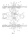
- Figure 1 is a schematic top view of equipment of the invention.
- the equipment is meant for loading roll containers with products consisting of various bulk goods, such as dairy products. It is to be emphasised, however, that the embodiments of the invention are not restricted to the handling of a particular product.
- the equipment comprises a transfer device, which in the embodiment shown in the Figure is a robot 1, and two product conveyors 2.
- the described equipment further contains two roll container conveyors 3 and two loading and/or unloading points 4.
- the product conveyors 2 bring products 5 to the equipment for loading.
- the products 5 are first guided to grouping devices 6, each product conveyor 2 being provided with one.
- the grouping devices 6 form a level pattern 8, in a manner known per se, from the products 5 onto a grouping plane 7.
- the grouping plane may be any plane onto which products 5 can be placed.
- the level pattern 8 comprises a number of products 5 meant for a single shelf of a roll container 9, arranged according to the space available on the shelf.
- the shown level pattern 8 consists of a total of 16 products 5 arranged in four successive rows, with four products in each row.
- level pattern 8 Naturally it is also possible to have a different number of products in the level pattern 8, their number being determined by the size of the roll container 9, the size of the product, and whether an entire shelf is to be filled with one level pattern 8 or not.
- the product conveyor 2 is well known to a person skilled in the art and therefore it will not be discussed in greater detail in this context.
- the roll container conveyors 3 bring roll containers 9 into the loading and/or unloading point 4 for containerisation. Filled roll containers 9 are transferred for further handling on the same conveyors.
- the roll container conveyor 3 is fully known per se, and therefore it will not be discussed in greater detail in this context.
- the loading and/or unloading points 4 comprise two transfer elements 11 arranged on opposite sides of the roll container conveyor 3 and substantially parallel with it.
- the transfer elements 11 are configured to move relative to a frame 14 of the loading and/or unloading point 4.
- the robot 1, which in the Figure is a 4-degree of freedom robot, comprises a gripping device 10 that the robot 1 uses for gripping the products 5 to be containerised.
- the gripping device 10 shown in the Figure can be used for transferring all the products 5 in a level pattern 8 filling an entire roll container shelf at one go.
- the gripping device can, however, be replaced by various other gripping devices of different structure and operating principle for transferring one or more products at a time, as required.
- the gripping device 10 not only grips the products but also finishes the level pattern 8 to its final form suitable for the roll container 9.
- the transfer device may also be other than a robot.
- the Figure shows a manipulator 13 depicted with a line of dots and dashes.
- the robot 1 grips the level pattern 8 with the gripping device 10 and transfers the pattern to one of the loading and/or unloading points 4.
- the transfer elements 11 are pressed against the roll container 9 placed in the loading and/or unloading point 4 by means of power elements.
- the power elements are pneumatic cylinders 12, although they may naturally be of some other type as well.
- the transfer elements 11 are provided with first and second turning members, the operation and structure of which will be described in greater detail below. Briefly described, the loading of an empty roll container with products is carried out as follows: the turning members first turn the shelves of the roll container 9 into a vertical position parallel with the side walls of the container. This provides free access to the bottom of the roll container 9 from above.
- the robot 1 takes a product pattern 8 that is in the gripping device 10 to the bottom from above. When the product pattern 8 that is to be containerised has been placed to the bottom of the roll container and the gripping device 10 has moved away, the lowest shelf is turned into a horizontal position, i.e. its position of use.
- the robot 1 transfers the next product pattern 8 onto the shelf concerned, which is followed by the turning of the subsequent, upper shelf of the roll container 9 into its use position. The process continues until the roll container is loaded as desired, either completely or partly full. On the other hand, if products 5 are to be entered into an already partly loaded roll container 9, unloaded shelves are similarly turned into a vertical position to provide free access from above to the shelf that is to be loaded. The process then continues as described above.
- the equipment of the invention is also applicable in a reverse manner, i.e. for unloading products 5 from roll containers 9.
- the invention is also applicable in equipment that is capable of both loading and unloading roll containers 9. It is apparent that the product conveyors 2 can also be used for feeding the equipment with mutually differing products 5 and that different products 5 can be loaded and/or unloaded in one and the same roll container 9.
- FIGs 2a to 2d are schematic views of a method and arrangement of the invention seen from the direction of travel of the roll container conveyor.
- Figure 2a shows a roll container conveyor 3 which has been stopped so that the roll container 9 to be containerised stands in the loading and/or unloading point 4, between its transfer elements 11.
- the transfer elements 11 comprise first turning members 15 and second turning members 16.
- the turning members 15, 16 are arranged to the transfer element 11 in pairs such that a pair always comprises one first turning member 15 and one second turning member 16.
- the turning members of a pair have co-axial pivoting shafts 17.
- the position of the turning members 15, 16 about the pivoting shaft 7 is changed for example by means of pneumatic cylinders or other similar power elements known per se and not shown in the Figures.
- the turning members 15, 16 of the pairs are turnable from one position to another independent of one another.
- the turning members 15, 16 are implemented as plates made of steel or some other metal and having essentially the same width and length as the shelves in the roll container 9.
- the position of the turning members 15, 16 can be controlled for example by means of limit switches that indicate whether the turning members 15, 16 are turned to their extreme vertical or horizontal position.
- Figure 2a shows how the transfer elements 11 are brought into contact with the roll container 9 such that the first turning members 15 are in a substantially horizontal position and therefore enter into the roll container 9 under a hinge 19 of a corresponding shelf 18.
- the second turning members 16, in turn, are in a vertical position.
- the concept 'vertical' refers to the height direction of the roll container 9 placed into the loading and/or unloading point 4, and the concept 'horizontal' to the direction that is perpendicular to the vertical direction.
- the first turning members 15 are turned upwards into a substantially parallel position with the side walls 20.
- the shelves 18 are often in random positions: some are in their horizontal use position, others are vertical, parallel with the side walls 20 of the roll container, and yet others are in positions somewhere in-between the two extremes. Irrespective of the position of the shelves 18, they all turn into a vertical position together with the first turning members 15. A completely free route is thereby provided from above to the bottom level 21 of the roll container 9. In other words, the shelves of the roll container 9 are turned into a vertical position such that free access to the level to be containerised is obtained from above.
- the level to be containerised refers to the shelf 18 or the bottom level 21 of the roll container onto which products are to be transferred in a particular situation, and, correspondingly, when products 5 are to be unloaded from the roll container 9, it refers to the level from which products 5 are to be removed in a particular situation.
- the first turning members 15 provide the roll container 9 with a space of standard dimensions extending from top to bottom, thereby ensuring problem-free containerisation.
- the gripping device 10 of the transfer device lowers the products 5 to be containerised into the roll container 9 from above by means of a substantially vertical movement, indicated by arrow R.
- This substantially vertical movement may include some horizontal motion, for example just before the products are placed onto the level to be containerised.
- the roll container is totally empty and the products are therefore lowered onto the bottom level 21.
- the lowest shelves 18 are turned into their horizontal use position by pressing them with the second turning members 16 provided at the shelves in question, the turning movement being shown in Figure 2c by arrows D.
- the corresponding first turning members 15 turn, together with the shelf 18 and the second pivoting member 16, into their horizontal position of use.
- the second turning members 16 are turned back into the vertical position, the turning movement being shown in the Figure by arrows U. Now the products 5 meant for the lowest shelf 18 can be containerised. The procedure is repeated for each shelf 18.
- the containerisation continues from the bottom to the top, proceeding from a lower shelf 18 to an upper shelf 18 until the roll container 9 is full, or all products 5 meant for the roll container 9 are loaded.
- the transfer elements 11 are then withdrawn from the roll container 9 as shown in Figure 2d such that the first turning members 15 come out of the roll container 9 and reassume the position shown in Figure 2a.
- the roll container conveyor 3 transfers the roll container 9 away from the loading and/or unloading point 4, which is then ready to receive the next roll container 9 to be containerised.
- FIG 3 shows a schematic, partly sectional detailed side view of the turning members in an arrangement of the invention.
- the roll container 9 is arranged into the loading and/or unloading point 4 for containerisation.
- the first and the second turning members 15, 16 are turned into their vertical positions, i.e. the situation corresponds to the one shown in Figure 2b.
- Figure only provides a partial view of the turning members 15, 16 and the transfer element 11 of the loading and/or unloading point 4.
- the hinge 19 of the roll container shelf contains a spindle 25 which is substantially co-axial with the pivoting shaft 17 of the turning members 15, 16 attached to the transfer element 11. Due to this the turning members 15, 16 and the corresponding shelf 18 remain in a substantially same position in relation to each other during the turning movements. For simplicity of illustration, the shelf 18 is not shown in the Figure.
- the pivoting shaft 17 is provided with bearings 26 attached to the shaft at the inner circumferences, while to the outer circumference of the bearings 26 is attached a first pivoting arm 27 and a second pivoting arm 28.
- a first pivoting arm 27 To the first pivoting arm 27 is attached a first tie rod 29, and, correspondingly, to the second pivoting arm 28 a second tie rod 30.
- the second pivoting arm 28 shown in Figure 3 comprises fastening means 31 for a power element operating the second turning member 16.
- the fastening means 31 is implemented as a hole made through the pivoting arm, the power element being fastened to the hole by means of a locking pin, or the like.
- the power element is not shown in Figure 3, but it is of the type of a pneumatic cylinder, or other similar power element known per se.
- the first turning member 15 can be turned independently of the second turning member 16, and vice versa. In other words, when one of the members is turned, the other may remain unturned or, alternatively, turn simultaneously with the first one.
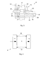
- FIG 4 is a schematic top view of the operation of an arrangement of the invention. It should be noted that like reference numerals are used in Figures 1, 2a to 2d, 3 and 4.
- the transfer element 11 in the loading and/or unloading point 4 is pressed against the roll container 9 depicted with a broken line.
- the transfer elements 11 are both provided with two substantially vertical straightening surfaces 32 attached to the elements at a distance from one another.
- the straightening surfaces 32 are substantially oblique in the direction of the roll container 9, and their distance is determined such that when the transfer elements 11 press against the roll container 9, the vertical edges of the roll container 9 are pressed between the straightening surfaces 32. If a slanting or bent roll container 9 arrives to the loading and/or unloading point 4, the straightening surfaces 32 straighten it into its proper shape.
- the roll containers 9 are of a substantially constant shape when they are containerised.
- the drawings and the related specification are only meant to illustrate the inventive idea.
- the details of the invention may vary within the scope of the claims. Consequently, it is fully evident that typical loading and/or unloading equipment naturally contains also other components and elements than those shown in the Figures.
- the equipment contains an appropriate number of product conveyors 2, roll container conveyors 3 and loading and/or unloading points 4 in each case. Also more than one transfer device, such as the robot 2, may be used.
- the equipment of the invention may comprise component assemblies different from those shown in the Figures; in addition, the components may be arranged in various other ways in relation to each other than what is shown in the Figures.
- the containerisation may produce mixed containers, i.e. various products 5 arranged into one and the same roll container 9.
- the loading and/or unloading point 4 may be provided with machine vision, laser measurement, or other similar measurement devices to check the dimensions of the roll container 9. If the dimensions exceed set tolerances, the roll container 9 is discarded and the next roll container 9 is received for loading and/or unloading.
- the equipment may be equipped with means for filling boxes or other packing. In that case the grouping plane 7 is made of two parts and can be opened. Below the plane, there is provided a box conveyor transferring boxes underneath the grouping plane 7 for filling. The products are dropped into a box by opening the grouping plane 7. This allows products unloaded from roll containers 9 to be placed into boxes.
- the operation of the roll container conveyors 3 may be synchronized such that when a roll container 9 on one roll container conveyor 3 is containerised, another roll container conveyor 3 transfers at the same time a roll container 9 into its loading and/or unloading point 4 for checking, eventual straightening and other similar measures. It is possible to both unload and load the same roll container 9 during one and the same containerisation procedure. It is also evident that the operation of the equipment is controlled by automated control devices, although for the sake of clarity they are not shown in the Figures.
Landscapes
- Engineering & Computer Science (AREA)
- Mechanical Engineering (AREA)
- Aviation & Aerospace Engineering (AREA)
- Warehouses Or Storage Devices (AREA)
- Replacement Of Web Rolls (AREA)
- Refuse Collection And Transfer (AREA)
- Loading Or Unloading Of Vehicles (AREA)
- Spinning Or Twisting Of Yarns (AREA)
- Stacking Of Articles And Auxiliary Devices (AREA)
- Pallets (AREA)
Abstract
Description
Claims (26)
- A method for loading or unloading roll containers, the method comprising a transfer device for transferring products (5) into and/or out of a roll container (9) comprising shelves (18), characterized in that the shelves (18) are moved such that the transfer device has free access to the level to be loaded or unloaded and that the products (5) are transferred by means of a substantially vertical movement into and/or out of the roll container (9).
- A method according to claim 1, characterized in that empty roll container shelves (18) are turned into a vertical position to provide free access from above to the roll container (9) level to be loaded or unloaded.
- A method according to claim 1 or 2, characterized in that when products (5) are transferred into the roll container (9), the shelf (18) that is next above the level whose loading has been completed is turned into use position.
- A method according to claim 1 or 2, characterized in that when products (5) are transferred out of the roll container (9), the shelf (18) whose unloading has been completed is turned into a vertical position.
- A method according to any one of the preceding claims, characterized in that the roll container (9) is arranged into a loading and/or unloading point (4) for the duration of the loading or unloading.
- A method according to claim 5, characterized in that the roll container (9) is arranged into the loading and/or unloading point (4) by means of a roll container conveyor (3).
- A method according to claim 5 or 6, characterized in that that the loading and/or unloading point (4) is provided with first turning members (15), which are pushed in a substantially horizontal direction under the shelves (18) of the roll container (9) and which upon turning from the horizontal position into a vertical position turn the corresponding shelf (18) from the use position into the vertical position substantially parallel with the side walls (20) of the roll container.
- A method according to claim 7, characterized in that that the loading and/or unloading point (4) is provided with second turning members (16), which are in a substantially vertical position when the first turning members (15) are pushed under the shelves (18) of the roll container (9) and which second turning members (16), upon turning from the vertical position into a horizontal position, turn the corresponding shelf (18) from the vertical position into the use position.
- A method according to any one of the preceding claims, characterized in that the transfer device is a robot (1).
- A method according to any one of claims 1 to 8, characterized in that the transfer device is a manipulator (13).
- Equipment for loading and unloading roll containers, the equipment comprising at least one grouping plane (7), at least one product transfer device, and at least one loading and/or unloading point (4) for loading or unloading a roll container (9) comprising shelves, characterized in that the loading and/or unloading point (4) comprises means for turning empty roll container shelves (18) into a vertical position to provide free access from above to the roll container (9) level that is to be loaded or unloaded, and that the product transfer device is arranged to transfer products into and/or out of the roll container (9) from above.
- Equipment according to claim 11, characterized in that the loading and/or unloading point (4) comprises means for turning roll container shelves (18) that are in the vertical position into a use position to allow products (5) to be loaded onto the shelf (18) concerned.
- Equipment according to claim 11 or 12, characterized in that the means for turning empty roll container shelves (18) into the vertical position comprise first turning members (15), which are arranged to be pushed in a substantially horizontal direction under the shelves (18) of the roll container (9) and which upon turning from the horizontal position into the vertical position are arranged to turn the corresponding shelf (18) from the use position into the vertical position substantially parallel with the side walls (20) of the roll container.
- Equipment according to claim 12 or 13, characterized in that the means for turning roll container shelves (18) from the vertical position into the use position comprise second turning members (16), which are arranged to be in a substantially vertical position when the first turning members (15) are arranged under the shelves (18) of the roll container (9) and which second turning members (16), upon turning from the vertical position into the horizontal position, are arranged to turn the corresponding shelf (18) from the vertical position into the use position.
- Equipment according to claim 13 or 14, characterized in that when the turning members are arranged under the shelves (18) of the roll container (9), the pivoting shaft (17) of the turning members is substantially co-axial with the spindle (25) of the hinge (19) of the corresponding shelf.
- Equipment according to any one of claims 11 to 15, characterized in that the transfer device is a robot (1).
- Equipment according to any one of claims 11 to 15, characterized in that the transfer device is a manipulator (13).
- Equipment according to any one of claims 11 to 17, characterized in that the equipment comprises at least one roll container conveyor (3), which is arranged to transfer roll containers (9) into and out of the loading and/or unloading point (4).
- Equipment according to any one of claims 11 to 18, characterized in that the equipment comprises at least one grouping device (6), which is arranged to receive products (15) and arrange them into a level pattern (8).
- An arrangement for loading or unloading roll containers, the arrangement comprising a loading and/or unloading point (4) which in turn comprises a frame (14) and a space for a roll container (9) to be loaded or unloaded, the roll container comprising at least one shelf (18), characterized in that the loading and/or unloading point (4) comprises means for turning empty roll container shelves (18) into a vertical position to provide free access from above to the roll container (9) level that is to be loaded or unloaded, and that the roll container (9) is configured to be loaded or unloaded from above.
- An arrangement according to claim 20, characterized in that that the loading and/or unloading point (4) comprises means for turning roll container shelves (18) that are in the vertical position into a use position to allow products (5) to be loaded onto the shelf (18) concerned.
- An arrangement according to claim 20 or 21, characterized in that the means for turning empty roll container shelves (18) into the vertical position comprise first turning members (15), which are arranged to be pushed in a substantially horizontal direction under the shelves (18) of the roll container (9) and which upon turning from the horizontal position into the vertical position are arranged to turn the corresponding shelf (18) from the use position into the vertical position substantially parallel with the side walls (20) of the roll container.
- An arrangement according to claim 21 or 22, characterized in that the means for turning roll container shelves (18) from the vertical position into the use position comprise second turning members (16), which are arranged into a substantially vertical position when the first turning members (15) are arranged under the shelves (18) of the roll container (9) and which second turning members (16), upon turning from the vertical position into the horizontal position, are arranged to turn the corresponding shelf (18) from the vertical position into the use position.
- An arrangement according to claim 22 or 23, characterized in that when the turning members are arranged under the shelves (18) of the roll container (9), the pivoting shaft (17) of the turning members is substantially co-axial with the spindle (25) of the hinge (19) of the corresponding shelf.
- An arrangement according to any one of claims 22 to 24, characterized in that the first turning members (15) are formed of a plate which is dimensioned to be substantially equal to the shelf (18) of the roll container (9).
- An arrangement according to any one of claims 20 to 25, characterized in that the loading and/or unloading point (4) is provided with straightening surfaces (32) for roll containers (9).
Applications Claiming Priority (2)
| Application Number | Priority Date | Filing Date | Title |
|---|---|---|---|
| FI20011449 | 2001-07-03 | ||
| FI20011449A FI114628B (en) | 2001-07-03 | 2001-07-03 | Procedure, apparatus and arrangement for loading container containers |
Publications (3)
| Publication Number | Publication Date |
|---|---|
| EP1273539A2 true EP1273539A2 (en) | 2003-01-08 |
| EP1273539A3 EP1273539A3 (en) | 2003-11-12 |
| EP1273539B1 EP1273539B1 (en) | 2006-01-25 |
Family
ID=8561575
Family Applications (1)
| Application Number | Title | Priority Date | Filing Date |
|---|---|---|---|
| EP02396110A Expired - Lifetime EP1273539B1 (en) | 2001-07-03 | 2002-07-01 | Method and arrangement for loading or unloading roll containers |
Country Status (5)
| Country | Link |
|---|---|
| EP (1) | EP1273539B1 (en) |
| AT (1) | ATE316506T1 (en) |
| DE (1) | DE60208874T2 (en) |
| FI (1) | FI114628B (en) |
| NO (1) | NO323355B1 (en) |
Cited By (1)
| Publication number | Priority date | Publication date | Assignee | Title |
|---|---|---|---|---|
| NO20200909A1 (en) * | 2020-08-18 | 2022-02-21 | Robotnorge As | Apparatus for adapting at least one roll container from a nestable configuration to a fillable configuration |
Families Citing this family (1)
| Publication number | Priority date | Publication date | Assignee | Title |
|---|---|---|---|---|
| DE102021205138A1 (en) | 2021-05-20 | 2022-11-24 | Psa Automobiles Sa | transport vehicle |
Family Cites Families (5)
| Publication number | Priority date | Publication date | Assignee | Title |
|---|---|---|---|---|
| US3637095A (en) * | 1969-07-08 | 1972-01-25 | Conveyor Specialties Co | Cart-loading machine |
| GB1342895A (en) * | 1971-04-19 | 1974-01-03 | Caxtonia Ltd | Transporter |
| SE448447B (en) * | 1985-04-25 | 1987-02-23 | Tetra Pak Int | LASTBERARE |
| GB9221971D0 (en) * | 1992-10-20 | 1992-12-02 | Elopak Systems | A goods container |
| US5927927A (en) * | 1997-09-08 | 1999-07-27 | C.J. Machine Inc. | Automatic cart loading machine and method |
-
2001
- 2001-07-03 FI FI20011449A patent/FI114628B/en not_active IP Right Cessation
-
2002
- 2002-06-28 NO NO20023177A patent/NO323355B1/en not_active IP Right Cessation
- 2002-07-01 EP EP02396110A patent/EP1273539B1/en not_active Expired - Lifetime
- 2002-07-01 DE DE60208874T patent/DE60208874T2/en not_active Expired - Lifetime
- 2002-07-01 AT AT02396110T patent/ATE316506T1/en active
Cited By (2)
| Publication number | Priority date | Publication date | Assignee | Title |
|---|---|---|---|---|
| NO20200909A1 (en) * | 2020-08-18 | 2022-02-21 | Robotnorge As | Apparatus for adapting at least one roll container from a nestable configuration to a fillable configuration |
| NO346887B1 (en) * | 2020-08-18 | 2023-02-13 | Robotnorge As | Apparatus and system for adapting at least one roll container from a nestable configuration to a fillable configuration, and a jig for guiding at least one part of a roll container |
Also Published As
| Publication number | Publication date |
|---|---|
| FI20011449L (en) | 2003-01-04 |
| NO20023177D0 (en) | 2002-06-28 |
| FI114628B (en) | 2004-11-30 |
| DE60208874T2 (en) | 2006-11-02 |
| ATE316506T1 (en) | 2006-02-15 |
| NO20023177L (en) | 2003-01-06 |
| DE60208874D1 (en) | 2006-04-13 |
| EP1273539B1 (en) | 2006-01-25 |
| FI20011449A0 (en) | 2001-07-03 |
| EP1273539A3 (en) | 2003-11-12 |
| NO323355B1 (en) | 2007-04-10 |
Similar Documents
| Publication | Publication Date | Title |
|---|---|---|
| US6520317B2 (en) | Packaging and casing system | |
| US9776753B2 (en) | Method and device for conveying piece goods in a filling machine | |
| US5339606A (en) | Method for accepting continuously supplied products from a production facility and respectively discontinuous delivery of a number of these products at a delivery station | |
| US6398008B1 (en) | Aligning and conveying method of packaged article and apparatus thereof | |
| US5079903A (en) | Gripping head for loading packages into crates | |
| EP1231170A1 (en) | Machine for the supply of empty cardboard boxes | |
| US20240043230A1 (en) | apparatus for tipping boxes | |
| US5261521A (en) | Apparatus for turning small goods, particularly packages, on a conveyor belt | |
| WO2011066897A1 (en) | Device for handling large packages comprising a plurality of articles as the content of the packages | |
| EP1273539B1 (en) | Method and arrangement for loading or unloading roll containers | |
| JP2003302280A (en) | Automatic marking device for metal ingots | |
| US6854588B1 (en) | Tray conveyor/loading system | |
| EP0480533B1 (en) | Block filling apparatus | |
| US5862649A (en) | Method and device for packaging cans or tubes | |
| JP7574823B2 (en) | INTERCONTAINER TRANSFER DEVICE AND INTERCONTAINER TRANSFER METHOD | |
| AT18396U1 (en) | transfer station for packing robots | |
| US20240262629A1 (en) | Apparatus and method for automatically introducing objects into boxes | |
| JP2020117310A (en) | Bag take-out method and bag take-out device | |
| JP2000142968A (en) | Individual feeder with row independent transport | |
| JP3431199B2 (en) | Automatic box packing and box straightening machine | |
| US3299613A (en) | Carton carrier | |
| GB2131763A (en) | Apparatus for palletising, layer by layer on relative pallets, objects of various kinds originating from separate channels | |
| CN223751169U (en) | Automatic change vanning device | |
| JPS6396017A (en) | Method and device for exchanging cell plate of filler with vessel receiving section | |
| CA1338684C (en) | Apparatus for unpacking cases |
Legal Events
| Date | Code | Title | Description |
|---|---|---|---|
| PUAI | Public reference made under article 153(3) epc to a published international application that has entered the european phase |
Free format text: ORIGINAL CODE: 0009012 |
|
| AK | Designated contracting states |
Kind code of ref document: A2 Designated state(s): AT BE BG CH CY CZ DE DK EE ES FI FR GB GR IE IT LI LU MC NL PT SE SK TR |
|
| AX | Request for extension of the european patent |
Free format text: AL;LT;LV;MK;RO;SI |
|
| PUAL | Search report despatched |
Free format text: ORIGINAL CODE: 0009013 |
|
| AK | Designated contracting states |
Kind code of ref document: A3 Designated state(s): AT BE BG CH CY CZ DE DK EE ES FI FR GB GR IE IT LI LU MC NL PT SE SK TR |
|
| AX | Request for extension of the european patent |
Extension state: AL LT LV MK RO SI |
|
| 17P | Request for examination filed |
Effective date: 20040220 |
|
| 17Q | First examination report despatched |
Effective date: 20040611 |
|
| AKX | Designation fees paid |
Designated state(s): AT BE BG CH CY CZ DE DK EE ES FI FR GB GR IE IT LI LU MC NL PT SE SK TR |
|
| AXX | Extension fees paid |
Extension state: AL Payment date: 20040220 Extension state: SI Payment date: 20040220 Extension state: RO Payment date: 20040220 Extension state: LV Payment date: 20040220 Extension state: LT Payment date: 20040220 Extension state: MK Payment date: 20040220 |
|
| RAP1 | Party data changed (applicant data changed or rights of an application transferred) |
Owner name: NEKOMAT-BELOS OY Owner name: TETRA LAVAL HOLDINGS & FINANCE S.A. |
|
| REG | Reference to a national code |
Ref country code: SE Ref legal event code: TRCL |
|
| GRAP | Despatch of communication of intention to grant a patent |
Free format text: ORIGINAL CODE: EPIDOSNIGR1 |
|
| RTI1 | Title (correction) |
Free format text: METHOD AND ARRANGEMENT FOR LOADING OR UNLOADING ROLL CONTAINERS |
|
| GRAS | Grant fee paid |
Free format text: ORIGINAL CODE: EPIDOSNIGR3 |
|
| GRAA | (expected) grant |
Free format text: ORIGINAL CODE: 0009210 |
|
| AK | Designated contracting states |
Kind code of ref document: B1 Designated state(s): AT BE BG CH CY CZ DE DK EE ES FI FR GB GR IE IT LI LU MC NL PT SE SK TR |
|
| AX | Request for extension of the european patent |
Extension state: AL LT LV MK RO SI |
|
| PG25 | Lapsed in a contracting state [announced via postgrant information from national office to epo] |
Ref country code: IT Free format text: LAPSE BECAUSE OF FAILURE TO SUBMIT A TRANSLATION OF THE DESCRIPTION OR TO PAY THE FEE WITHIN THE PRESCRIBED TIME-LIMIT;WARNING: LAPSES OF ITALIAN PATENTS WITH EFFECTIVE DATE BEFORE 2007 MAY HAVE OCCURRED AT ANY TIME BEFORE 2007. THE CORRECT EFFECTIVE DATE MAY BE DIFFERENT FROM THE ONE RECORDED. Effective date: 20060125 Ref country code: FI Free format text: LAPSE BECAUSE OF FAILURE TO SUBMIT A TRANSLATION OF THE DESCRIPTION OR TO PAY THE FEE WITHIN THE PRESCRIBED TIME-LIMIT Effective date: 20060125 Ref country code: SK Free format text: LAPSE BECAUSE OF FAILURE TO SUBMIT A TRANSLATION OF THE DESCRIPTION OR TO PAY THE FEE WITHIN THE PRESCRIBED TIME-LIMIT Effective date: 20060125 Ref country code: BE Free format text: LAPSE BECAUSE OF FAILURE TO SUBMIT A TRANSLATION OF THE DESCRIPTION OR TO PAY THE FEE WITHIN THE PRESCRIBED TIME-LIMIT Effective date: 20060125 Ref country code: CH Free format text: LAPSE BECAUSE OF FAILURE TO SUBMIT A TRANSLATION OF THE DESCRIPTION OR TO PAY THE FEE WITHIN THE PRESCRIBED TIME-LIMIT Effective date: 20060125 Ref country code: LI Free format text: LAPSE BECAUSE OF FAILURE TO SUBMIT A TRANSLATION OF THE DESCRIPTION OR TO PAY THE FEE WITHIN THE PRESCRIBED TIME-LIMIT Effective date: 20060125 |
|
| REG | Reference to a national code |
Ref country code: GB Ref legal event code: FG4D |
|
| REG | Reference to a national code |
Ref country code: CH Ref legal event code: EP |
|
| REG | Reference to a national code |
Ref country code: IE Ref legal event code: FG4D |
|
| REF | Corresponds to: |
Ref document number: 60208874 Country of ref document: DE Date of ref document: 20060413 Kind code of ref document: P |
|
| PG25 | Lapsed in a contracting state [announced via postgrant information from national office to epo] |
Ref country code: DK Free format text: LAPSE BECAUSE OF FAILURE TO SUBMIT A TRANSLATION OF THE DESCRIPTION OR TO PAY THE FEE WITHIN THE PRESCRIBED TIME-LIMIT Effective date: 20060425 Ref country code: BG Free format text: LAPSE BECAUSE OF FAILURE TO SUBMIT A TRANSLATION OF THE DESCRIPTION OR TO PAY THE FEE WITHIN THE PRESCRIBED TIME-LIMIT Effective date: 20060425 |
|
| PG25 | Lapsed in a contracting state [announced via postgrant information from national office to epo] |
Ref country code: ES Free format text: LAPSE BECAUSE OF FAILURE TO SUBMIT A TRANSLATION OF THE DESCRIPTION OR TO PAY THE FEE WITHIN THE PRESCRIBED TIME-LIMIT Effective date: 20060506 |
|
| REG | Reference to a national code |
Ref country code: SE Ref legal event code: TRGR |
|
| PG25 | Lapsed in a contracting state [announced via postgrant information from national office to epo] |
Ref country code: PT Free format text: LAPSE BECAUSE OF FAILURE TO SUBMIT A TRANSLATION OF THE DESCRIPTION OR TO PAY THE FEE WITHIN THE PRESCRIBED TIME-LIMIT Effective date: 20060626 |
|
| LTIE | Lt: invalidation of european patent or patent extension |
Effective date: 20060125 |
|
| PG25 | Lapsed in a contracting state [announced via postgrant information from national office to epo] |
Ref country code: MC Free format text: LAPSE BECAUSE OF NON-PAYMENT OF DUE FEES Effective date: 20060731 |
|
| REG | Reference to a national code |
Ref country code: CH Ref legal event code: PL |
|
| PLBE | No opposition filed within time limit |
Free format text: ORIGINAL CODE: 0009261 |
|
| STAA | Information on the status of an ep patent application or granted ep patent |
Free format text: STATUS: NO OPPOSITION FILED WITHIN TIME LIMIT |
|
| 26N | No opposition filed |
Effective date: 20061026 |
|
| PG25 | Lapsed in a contracting state [announced via postgrant information from national office to epo] |
Ref country code: CZ Free format text: LAPSE BECAUSE OF FAILURE TO SUBMIT A TRANSLATION OF THE DESCRIPTION OR TO PAY THE FEE WITHIN THE PRESCRIBED TIME-LIMIT Effective date: 20060125 Ref country code: GR Free format text: LAPSE BECAUSE OF FAILURE TO SUBMIT A TRANSLATION OF THE DESCRIPTION OR TO PAY THE FEE WITHIN THE PRESCRIBED TIME-LIMIT Effective date: 20060426 Ref country code: FR Free format text: LAPSE BECAUSE OF FAILURE TO SUBMIT A TRANSLATION OF THE DESCRIPTION OR TO PAY THE FEE WITHIN THE PRESCRIBED TIME-LIMIT Effective date: 20070316 |
|
| PG25 | Lapsed in a contracting state [announced via postgrant information from national office to epo] |
Ref country code: EE Free format text: LAPSE BECAUSE OF FAILURE TO SUBMIT A TRANSLATION OF THE DESCRIPTION OR TO PAY THE FEE WITHIN THE PRESCRIBED TIME-LIMIT Effective date: 20060125 |
|
| PG25 | Lapsed in a contracting state [announced via postgrant information from national office to epo] |
Ref country code: TR Free format text: LAPSE BECAUSE OF FAILURE TO SUBMIT A TRANSLATION OF THE DESCRIPTION OR TO PAY THE FEE WITHIN THE PRESCRIBED TIME-LIMIT Effective date: 20060125 Ref country code: LU Free format text: LAPSE BECAUSE OF NON-PAYMENT OF DUE FEES Effective date: 20060701 |
|
| PG25 | Lapsed in a contracting state [announced via postgrant information from national office to epo] |
Ref country code: FR Free format text: LAPSE BECAUSE OF FAILURE TO SUBMIT A TRANSLATION OF THE DESCRIPTION OR TO PAY THE FEE WITHIN THE PRESCRIBED TIME-LIMIT Effective date: 20060125 Ref country code: CY Free format text: LAPSE BECAUSE OF FAILURE TO SUBMIT A TRANSLATION OF THE DESCRIPTION OR TO PAY THE FEE WITHIN THE PRESCRIBED TIME-LIMIT Effective date: 20060125 |
|
| PGFP | Annual fee paid to national office [announced via postgrant information from national office to epo] |
Ref country code: NL Payment date: 20150720 Year of fee payment: 14 |
|
| PGFP | Annual fee paid to national office [announced via postgrant information from national office to epo] |
Ref country code: DE Payment date: 20150727 Year of fee payment: 14 Ref country code: IE Payment date: 20150715 Year of fee payment: 14 Ref country code: GB Payment date: 20150728 Year of fee payment: 14 |
|
| PGFP | Annual fee paid to national office [announced via postgrant information from national office to epo] |
Ref country code: AT Payment date: 20150720 Year of fee payment: 14 |
|
| REG | Reference to a national code |
Ref country code: DE Ref legal event code: R119 Ref document number: 60208874 Country of ref document: DE |
|
| REG | Reference to a national code |
Ref country code: NL Ref legal event code: MM Effective date: 20160801 |
|
| REG | Reference to a national code |
Ref country code: AT Ref legal event code: MM01 Ref document number: 316506 Country of ref document: AT Kind code of ref document: T Effective date: 20160701 |
|
| GBPC | Gb: european patent ceased through non-payment of renewal fee |
Effective date: 20160701 |
|
| PG25 | Lapsed in a contracting state [announced via postgrant information from national office to epo] |
Ref country code: NL Free format text: LAPSE BECAUSE OF NON-PAYMENT OF DUE FEES Effective date: 20160801 Ref country code: DE Free format text: LAPSE BECAUSE OF NON-PAYMENT OF DUE FEES Effective date: 20170201 |
|
| REG | Reference to a national code |
Ref country code: IE Ref legal event code: MM4A |
|
| PG25 | Lapsed in a contracting state [announced via postgrant information from national office to epo] |
Ref country code: GB Free format text: LAPSE BECAUSE OF NON-PAYMENT OF DUE FEES Effective date: 20160701 Ref country code: AT Free format text: LAPSE BECAUSE OF NON-PAYMENT OF DUE FEES Effective date: 20160701 |
|
| PG25 | Lapsed in a contracting state [announced via postgrant information from national office to epo] |
Ref country code: IE Free format text: LAPSE BECAUSE OF NON-PAYMENT OF DUE FEES Effective date: 20160701 |
|
| PGFP | Annual fee paid to national office [announced via postgrant information from national office to epo] |
Ref country code: SE Payment date: 20190722 Year of fee payment: 18 |
|
| REG | Reference to a national code |
Ref country code: SE Ref legal event code: EUG |
|
| PG25 | Lapsed in a contracting state [announced via postgrant information from national office to epo] |
Ref country code: SE Free format text: LAPSE BECAUSE OF NON-PAYMENT OF DUE FEES Effective date: 20200702 |