EP1272813B1 - Inclinometre a reseau de bragg - Google Patents
Inclinometre a reseau de bragg Download PDFInfo
- Publication number
- EP1272813B1 EP1272813B1 EP01923779A EP01923779A EP1272813B1 EP 1272813 B1 EP1272813 B1 EP 1272813B1 EP 01923779 A EP01923779 A EP 01923779A EP 01923779 A EP01923779 A EP 01923779A EP 1272813 B1 EP1272813 B1 EP 1272813B1
- Authority
- EP
- European Patent Office
- Prior art keywords
- inclinometer
- bragg
- optic fibre
- articulation
- portions
- Prior art date
- Legal status (The legal status is an assumption and is not a legal conclusion. Google has not performed a legal analysis and makes no representation as to the accuracy of the status listed.)
- Expired - Lifetime
Links
Images



Classifications
-
- G—PHYSICS
- G01—MEASURING; TESTING
- G01B—MEASURING LENGTH, THICKNESS OR SIMILAR LINEAR DIMENSIONS; MEASURING ANGLES; MEASURING AREAS; MEASURING IRREGULARITIES OF SURFACES OR CONTOURS
- G01B11/00—Measuring arrangements characterised by the use of optical techniques
- G01B11/16—Measuring arrangements characterised by the use of optical techniques for measuring the deformation in a solid, e.g. optical strain gauge
- G01B11/165—Measuring arrangements characterised by the use of optical techniques for measuring the deformation in a solid, e.g. optical strain gauge by means of a grating deformed by the object
-
- G—PHYSICS
- G01—MEASURING; TESTING
- G01B—MEASURING LENGTH, THICKNESS OR SIMILAR LINEAR DIMENSIONS; MEASURING ANGLES; MEASURING AREAS; MEASURING IRREGULARITIES OF SURFACES OR CONTOURS
- G01B11/00—Measuring arrangements characterised by the use of optical techniques
- G01B11/26—Measuring arrangements characterised by the use of optical techniques for measuring angles or tapers; for testing the alignment of axes
-
- G—PHYSICS
- G01—MEASURING; TESTING
- G01B—MEASURING LENGTH, THICKNESS OR SIMILAR LINEAR DIMENSIONS; MEASURING ANGLES; MEASURING AREAS; MEASURING IRREGULARITIES OF SURFACES OR CONTOURS
- G01B11/00—Measuring arrangements characterised by the use of optical techniques
- G01B11/16—Measuring arrangements characterised by the use of optical techniques for measuring the deformation in a solid, e.g. optical strain gauge
- G01B11/18—Measuring arrangements characterised by the use of optical techniques for measuring the deformation in a solid, e.g. optical strain gauge using photoelastic elements
-
- G—PHYSICS
- G01—MEASURING; TESTING
- G01C—MEASURING DISTANCES, LEVELS OR BEARINGS; SURVEYING; NAVIGATION; GYROSCOPIC INSTRUMENTS; PHOTOGRAMMETRY OR VIDEOGRAMMETRY
- G01C9/00—Measuring inclination, e.g. by clinometers, by levels
- G01C9/12—Measuring inclination, e.g. by clinometers, by levels by using a single pendulum
Definitions
- the present invention relates to a inclinometer, that is to say a device intended to measure variations of inclination.
- the invention is particularly useful in mining, drilling, in the field of civil engineering, for the supervision of structures (for example, bridges and tunnels) and buildings (in particular historical monuments), and wherever a control precise stability of a structure is required, especially in the long run.
- structures for example, bridges and tunnels
- buildings in particular historical monuments
- extensometers Classically, in civil engineering, instruments called “extensometers” are used to monitor deformations. Various extensometers are commercially available.
- tiltmeters electric inclinometers
- tiltmeters which are used to monitor the change of the inclination of points located on the floor or in the floor or arranged on a structure.
- These inclinometers consist of a sensor that is sensitive to gravity (pendulum) and arranged in a suitable housing.
- pendulum a sensor that is sensitive to gravity
- Several types inclinometers are known.
- an inclinometer mechanical which consists of a beam and a level to bubble, with an upgrade setting to one of its ends.
- This beam is fixed on two spheres of anchored on the system to be measured. Adjustment leveling is done by adjusting the bubble level and a rev counter dial is used to make the measured.
- the measuring range is typically a few degrees.
- the accuracy is approximately ⁇ 0.013 millimeter for a beam 200 millimeters long (about 60 ⁇ rad) and is reduced to ⁇ 0.13 millimeter for a beam 900 millimeters long (ie about 150 ⁇ rad).
- an inclinometer comprising an accelerometric sensor. The measurement is made in placing the inclinometer in a reproducible position on a reference flat part. We perform a first reading then we turn the sensor 180 degrees and we do a second reading.
- the flat piece reference is metallic or ceramic and shall be firmly attached to a surface that you want control.
- the measurement range is from -30 ° to + 30 ° and the accuracy is typically ⁇ 250 ⁇ rad.
- the measurement range is typically -0.11 ° at + 0.11 ° with a precision of about 0.5% of the full scale (approximately ⁇ 10 ⁇ rad to ⁇ 100 ⁇ rad).
- an inclinometer having an electrolytic level sensor.
- a measurement cell in glass containing an electrically conductive liquid is sealed in its two ends.
- the measurement accuracy of this type of sensor is average.
- its thermal sensitivity is high. As a result, it does not fit very well geotechnical or civil engineering applications.
- the empty is done in the measuring cell.
- the performance is better. Nevertheless, a calibration specific is required for each cell and recalibrations are necessary.
- Such inclinometers are expensive especially when used in a network ("Network").
- a Bragg grating photo-inscribed in an optical fiber consists of a periodic structure formed by a modulation of the refractive index of the core of the optical fiber.
- Such a structure behaves almost like a mirror for a very fine spectral band around a characteristic wavelength ⁇ B (wavelength for which there is phase agreement between the multiple reflections within the network) and remains transparent for all other wavelengths. Indeed, the multiple waves reflected at these other wavelengths are not in phase, interfere destructively in reflection and are therefore transmitted.
- the final characteristics of a photo-inscribed Bragg grating depend on the inscription parameters such as the type of laser (wavelength, operating regime) and the light power used, the wavelength ⁇ at which this network is recorded, the effective index n eff of the optical fiber in which it is inscribed, the amplitude of the modulation or index variation ⁇ n and the period ⁇ of this index variation.
- These parameters determine the characteristic quantities of the Bragg grating, namely: the Bragg wavelength ⁇ B , the reflectivity R max at ⁇ B , and the width at half height of the reflectivity peak, as well as the propensity of the grating. to withstand large temperature variations or high elongations, which is an important aspect for using this Bragg grating as a transducer.
- the characteristic wavelength ⁇ B depends on the temperature and the stresses ( ⁇ x, ⁇ y, ⁇ z) applied to the fiber in which the network is formed.
- the Bragg grating is therefore "Transducer” since it transforms evolutions from a magnitude of influence to a spectral shift proportional to these developments.
- the coefficient a ' is substantially 7.8-10 -6 / ° C.
- n e , ⁇ z , E, ⁇ and p e respectively represent the optical index of the core of the fiber, the relative length variation of the fiber (deformation along the z axis of the fiber), the Young's modulus , the Poisson's ratio and the photo-elastic constant of the material constituting the fiber;
- p 11 and p 12 are elasto-optical coefficients.
- the coefficient b ' is approximately 0.78 x 10 -6 / ( ⁇ m / m).
- the coefficient c ' is approximately -2.7x10 -6 / MPa.
- the sensitivity values of Bragg gratings photo-inscribed in silica optical fibers are grouped together in Table I for the most important parameters (temperature, deformations and pressure) for the three main wavelengths used.
- An optical fiber containing such networks Bragg can therefore serve as a deformation sensor.
- the measurement system of these deformations can then be understand a broad-spectrum optical source and a spectral analysis system (for example spectrophotometer or interferometric cavity type Fabry-Perot) or a narrow scanning source (of type tunable laser).
- a spectral analysis system for example spectrophotometer or interferometric cavity type Fabry-Perot
- a narrow scanning source of type tunable laser.
- the addition of Bragg gratings of reference allows an absolute spectral location of the wavelength peaks that are reflected by Measure Bragg gratings.
- the present invention relates to a inclinometer which is insensitive to disturbances electromagnetic fields and who, for this purpose, uses a or a plurality of optical fibers as well as at least a Bragg grating as a transducer.
- measurements of spectral type make it possible to overcome fluctuations in light intensity.
- the inclinometer object of the invention comprises at least two Bragg networks, these two Bragg networks being respectively formed in the two fiber portions optical and thus undergoing respectively a tensile stress and compressive stress during the variation of inclination of the structure, these Bragg gratings for differential measurement of wavelength, the inclinometer then being insensitive to changes in temperature and pressure ambient.
- the articulation of the lower and superior of the inclinometer object of the invention can include an axis of rotation to be arranged horizontally when measuring variation of inclination.
- the articulation of lower and upper parts has at least two degrees of freedom of rotation, this inclinometer comprising at minus three portions of fiber optic voltage and placed around this joint and at least two Bragg networks, these two Bragg networks being respectively formed in two of the three portions of optical fiber, the inclinometer then being provided for measure a variation of inclination definable by two angles of rotation. It is more advantageous to form a third Bragg network in the third portion of optical fiber, in order to obtain a third measure, used to compensate for the effect of temperature.
- the three portions of optical fiber can for example be arranged advantageously to 120 ° C from each other around the joint.
- the inclinometer can four fiber optic portions voltage and arranged at 90 ° from each other around of articulation, and in addition at least two networks of Bragg, these two Bragg networks being respectively formed in two of the four portions of optical fiber and to measure respectively the two anal.
- the inclinometer can understand four Bragg networks that are respectively formed in the four fiber portions optical, each Bragg network being associated with the network of Bragg who is opposed to him in relation to the articulation, these associated Bragg networks allowing a differential measurement of length waveform, the inclinometer then being insensitive to ambient temperature and pressure variations.
- the joint having at least two degrees of rotational freedom may comprise a ball joint or Cardan type suspension, or a tip supported on a hard surface.
- the inclinometer object of the invention can understand a single optical fiber to which belongs each portion of optical fiber.
- a plurality can be used inclinometers according to the invention, these inclinometers being serially connected via of the optical fiber.
- the inclinometer object of the invention can, in a particular embodiment, to be interrogated in reflection, by at least one of the ends of the fiber in which is or are formed the Bragg networks.
- This inclinometer is intended to measure a variation of inclination of a structure.
- this structure is a wall 2 of a building. It is assumed that the wall was initially vertically (inclination of a zero angle) and that inclined at an angle ⁇ (to the left of Figure 1).
- the inclinometer includes a part superior 4 and a lower part 6 as well as a articulation 8 of these parts 4 and 6.
- the inclinometer also comprises a hollow body 10 in which find parts 4 and 6 and articulation 8.
- the body 10 is provided with means 12 of attachment to the wall 2.
- the upper part 4 is fixed to the body 10 and therefore moves with the environment of the inclinometer (the wall 2 in the example).
- the hinge 8 comprises an axis of rotation 14 and the lower part 6 (placed below the upper part 4) has a mass 16 of value M. It is thus sensitive to the gravity characterized by a vector g and tends to stay vertically oriented. Thanks to the mass 16, the lower part forms a pendulum freely suspended at the top by means of the axis of rotation 14.
- the inclinometer also includes a fiber 18. Two portions 20 and 22 of this fiber are placed on either side of the axis of rotation. more, the ends A and B of the fiber portion 20 are attached respectively to the upper and lower bottom of the inclinometer. Similarly, the C ends and D of the fiber portion 22 are respectively attached to these upper and lower parts.
- a network of Bragg 24 is photo-inscribed in the heart of the fiber portion 20 and a network of Bragg 26, identical to network 24, is photo-inscribed in the heart of the fiber portion 22.
- a network of Bragg 26 identical to network 24, is photo-inscribed in the heart of the fiber portion 22.
- This opposition arrangement allows a measurement differential wavelength.
- the principle of the inclinometer of the figure 1 is to transform the angle rotation ⁇ that it undergoes in a stress level that is proportional to angle ⁇ and applied to Bragg gratings.
- ⁇ 0 is noted the strain induced in the fiber portions 20 and 22 by pre-tensioning thereof, ⁇ 1 the stress induced by the rotation of angle ⁇ on the Bragg grating 20 and ⁇ 2 the stress induced by this rotation on the Bragg network 22.
- ⁇ 1 - ⁇ 2 is measured where ⁇ 1 (respectively ⁇ 2 ) is the difference between the Bragg wavelength of the grating 20 (respectively of the grating 22) when the temperature is equal to T 0 + ⁇ T and the applied stress is worth ⁇ 0 + ⁇ 1 (respectively ⁇ 0 + ⁇ 2 ) and the Bragg wavelength of this same network 20 (respectively of the same network 22) when the temperature is equal to T 0 and the applied stress is worth ⁇ 0 .
- ⁇ 1 and ⁇ 2 have the same absolute value as ⁇ , but are of opposite signs, and the result of the measurement is 2.b. ⁇ .
- This inclinometer is therefore intrinsically insensitive to changes in ambient temperature.
- L f as a function of A 0 which represents the distance between the axis of rotation and the lower fixation point B (respectively D) of the fiber 20 (respectively 22) in FIG. 1, and of ⁇ 0 :
- This inclinometer can be likened to a rotating system. At equilibrium, we can write to you that the sum of the moments of the forces that are applied is null.
- ⁇ / ⁇ can be expressed in [( ⁇ m / m) / ⁇ rad] or in [( ⁇ m / m) / degree] and represents the sensitivity of the inclinometer, 1 ⁇ m / m being generally referred to as a microdeformation, denoted 1 ⁇ (or ⁇ strain in the Anglo-Saxon literature).
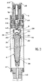
- FIG 3 is a sectional view longitudinal schematic of an inclinometer according to the invention.
- the part upper 4 of the inclinometer we find the part upper 4 of the inclinometer, the lower part 6 of the latter, comprising a mass 16 making office pendulum, the articulation 8 comprising an axis 14.
- This shaft is mounted on a precision ball bearing (not shown)
- optical fiber 18 we also see the optical fiber 18 as well that the portions 20 and 22 of this fiber, comprising respectively the Bragg gratings 24 and 26.
- the portion of fiber 20 is pretensioned by through two fastening systems or collage, or two jaws 28 and 30 which are respectively attached to the upper and lower.
- the portion of fiber 22 is pre-tensioned via two jaws 32 and 34 which are respectively attached to the upper parts and lower.
- the lower part of the optical fiber 18 through a curved hole 36 formed in the mass 16. From the more optical fiber 18 enters the inclinometer through an inlet 38 and out through an orifice 40, these orifices 38 and 40 being fixed to the upper part of the inclinometer.
- the inclinometer of FIG. in addition to an angular offset system, intended to replace the mass 16 vertically to make measurements when the body 10 of the inclinometer is not vertical and rests for example against a wall in slope.
- a particular example of such a system of original offset can be constituted by the system 44 which essentially comprises a breakthrough ball 46, who is mounted in a cage leaving this ball breakthrough, or ball joint, free in rotation, and an axis 48 which crosses the ball 46.
- the lower part of this axis 48 is connected to the upper part of the 8 joint while the upper part of the shaft 48 is movable by means of an adjusting rod 50.
- the adjustment of the system 44 can be done either before the assembly of the inclinometer on the structure to be measured variations of inclination, either after fixation according to the facilities of access.
- Figures 4 to 6 illustrate the compensation for temperature variations with a inclinometer of the kind shown in Figure 3, which uses a differential mount.
- the wavelength ⁇ (expressed in nm) is plotted on the abscissa and the intensity luminous I (expressed in arbitrary units) is on the ordinates.
- FIG. 8 schematically represents an exemplary measuring system containing six Bragg gratings of measurement R 1 , R 2 ... R 6 .
- an optical source SO and a spectral analysis system SA which are connected via an optical coupler CO, on the one hand to a measuring optical fiber Fm, in which are inscribed the Bragg gratings of measurement R 1. to R 6 , and secondly to a reference optical fiber Fr in which are inscribed two reference Bragg gratings Rr 1 and Rr 2 .
- Spectral analysis of reflected light by said Bragg gratings can be carried out following two modes.
- the preferential mode is the reflective mode. It also allows, in the event of fiber breakage, reconstruct all the spectral information, to condition to provide for a query by each of the ends of this fiber, either using a fiber optic switch alternately connecting the measuring system at each end, ie at using two measuring systems operating in alternately.
- FIG. 9 a system of measurement of inclination variations that incorporates the inclinometer of Figure 1 (or Figure 3).
- This system includes measuring means 52 allowing "To interrogate” the Bragg networks and to measure the variations of inclinations.
- These measuring means 52 are designed to send in the optical fiber 18 a spectrum of lights containing at least the different wavelengths ⁇ 1 and ⁇ 2 .
- each of the Bragg networks 24 and 26 alters the wavelength of the lights they think respectively and then these lights go back to ways measurement 52 through the optical fiber.
- the variation of inclination is determined by these measuring means from the variations spectral lights thus modified.
- the measuring means 52 are connected to the optical fiber via an optical switch 54 to alternate the interrogation (sending and light recovery) of Bragg gratings, this interrogation taking place alternately by one side 56 of the optical fiber then by the other side 58 of this fiber and so on, which helps to restore all the useful spectral information even in case of breaking the optical fiber at any point.
- the Bragg gratings are interrogated by a only side of the optical fiber 18, the other side being free.
- the lights are sent into the Bragg gratings on one side of the optical fiber 18 and recovering lights possibly modified, by the other side of optical fiber, to measure variations of inclination.
- FIG 12 we see a system of measuring variations of inclinations in different areas.
- This system comprises several inclinometers 60, 62 and 64 according to the invention (for example of the kind of that of Figure 1) which are respectively placed in these different areas.
- the same fiber optical 18 is common to all these inclinometers which are thus connected in series through this fiber.
- FIG 13 is a schematic view of a inclinometer according to the invention but without temperature compensation.
- This inclinometer is identical to the inclinometer in Figure 1 (or 3) except that it includes only one Bragg network, know the Bragg 24 network, no network being formed in the fiber portion 22.
- Such an inclinometer is usable in places where the temperature remains substantially constant, for example in mines.
- FIG. 14 Another inclinometer according to the invention is schematically represented on the Figure 14. This is a development of the inclinometer of FIG. 1, intended to measure variations of inclination that can be defined by two rotation angles (instead of one in the case of Figure 1).
- the articulation 8 of the inclinometer of the FIG. 14 comprises a ball 66 (or a suspension of Cardan type).
- this inclinometer includes no not two portions of optical fiber but four portions fiber optics 68, 70, 72 and 74 each subject to a pre-tension and respectively provided with four Photo-inscribed Bragg gratings 76, 78, 80 and 82.
- the portions of fiber 68 to 74 belong still to the same optical fiber 18.
- ⁇ 1 , ⁇ 2 , ⁇ 3 and ⁇ 4 are used which are sent into the optical fiber 18 and which are respectively associated with the Bragg gratings. , 78, 80 and 82.
- the inclinometer of Figure 15 is a refinement of that of Figure 14 and uses still the patella 66 but only three servings of fiber optics 84, 86 and 88 which are each subject to pre-tension and in which are respectively photo-inscribed three Bragg networks 90, 92 and 94.
- three lights of different wavelengths ⁇ 1 , ⁇ 2 and ⁇ 3 are used which are sent into the optical fiber 18 (to which belong the fiber portions 84, 86 and 88) and which are respectively associated with the Bragg gratings 90, 92 and 94.
Landscapes
- Physics & Mathematics (AREA)
- General Physics & Mathematics (AREA)
- Engineering & Computer Science (AREA)
- Radar, Positioning & Navigation (AREA)
- Remote Sensing (AREA)
- Length Measuring Devices By Optical Means (AREA)
- Optical Transform (AREA)
Description


| Sensibilité | λ=0,83 µm | λ=1,3 µm | λ=1,55 µm |
| Sensibilité thermique (pm/°C) | 6 , 5 | 10,1 | 12,1 |
| Sensibilité aux déformations (pm/µε) | 0,65 | 1,01 | 1,21 |
| Sensibilité à la pression hydrostatique (pm/MPa) | -2,4 | -3,7 | -4,5 |
- une partie supérieure destinée à être rendue rigidement solidaire de la structure afin que l'inclinaison de cette partie supérieure varie comme celle de la structure,
- une partie inférieure destinée à se trouver au-dessous de la partie supérieure,
- une articulation des parties inférieure et supérieure, la partie inférieure formant un pendule librement suspendu à la partie supérieure par cette articulation,
- au moins deux portions de fibre optique placées de part et d'autre de l'articulation, chaque portion de fibre optique ayant des première et deuxième extrémités qui sont respectivement fixées aux parties inférieure et supérieure et étant préalablement mise en tension entre ces parties inférieure et supérieure, et
- au moins un réseau de Bragg (« Bragg grating »), ce réseau de Bragg étant formé dans l'une des deux portions de fibre optique,
- la figure 1 illustre schématiquement le principe d'un mode de réalisation particulier de l'inclinomètre objet de l'invention,
- la figure 2 illustre schématiquement la partie centrale de l'inclinomètre de la figure 1,
- la figure 3 est une vue en coupe longitudinale schématique d'un mode de réalisation particulier de l'inclinomètre objet de l'invention,
- les figures 4, 5 et 6 sont des graphiques qui illustrent respectivement l'effet d'une simple rotation, l'effet d'une simple variation de température et l'effet combiné d'une rotation et d'une variation de température dans un exemple de l'inclinomètre objet de l'invention,
- la figure 7 est un graphique qui illustre schématiquement la compensation d'une variation de température dans un exemple de l'inclinomètre objet de l'invention,
- la figure 8 est une vue schématique d'un système comportant six réseaux de Bragg transducteurs et deux réseaux de Bragg de référence,
- les figures 9, 10 et 11 illustrent schématiquement des systèmes de mesure de variations d'inclinaison utilisant des inclinomètres conformes à l'invention,
- la figure 12 est une vue schématique d'un système de mesure de variations d'inclinaison dans plusieurs zones utilisant plusieurs inclinomètres conformes à l'invention montés en série,
- la figure 13 illustre très schématiquement un inclinomètre conforme à l'invention, n'utilisant qu'un seul réseau de Bragg, et
- les figures 14 et 15 illustrent très schématiquement des inclinomètres conformes à l'invention, permettant de mesurer des inclinaisons définissables par deux angles de rotation .



- la masse (voir figure 1) M induit un moment : M.g.Lm.sin(ψ)
- le réseau de Bragg 20 est sous contrainte et induit un moment M20=(F0+F1). R
- le réseau de Bragg 22 est sous contrainte et ce
réseau induit un moment M22=-(F0+F2).R où F0
représente le module de la force de pré-contrainte
et
F 1 est égal aF 2 et le module commun à ces deux forces est donné par la loi de Hooke et vaut donc Sf.Ef.ε.



Claims (12)
- Inclinomètre destiné à mesurer une variation d'inclinaison d'une structure, cet inclinomètre étant caractérisé en ce qu'il comprend :une partie supérieure (4) destinée à être rendue rigidement solidaire de la structure afin que l'inclinaison de cette partie supérieure varie comme celle de la structure,une partie inférieure (6) destinée à se trouver au-dessous de la partie supérieure,une articulation (8) des parties inférieure et supérieure, la partie inférieure formant un pendule librement suspendu à la partie supérieure par cette articulation,au moins deux portions de fibre optique (20, 22 ; 68, 70, 72, 74 ; 84, 86, 88) placées de part et d'autre de l'articulation, chaque portion de fibre optique ayant des première et deuxième extrémités qui sont respectivement fixées aux parties inférieure et supérieure et étant préalablement mise en tension entre ces parties inférieure et supérieure, etau moins un réseau de Bragg (24, 26 ; 76, 78, 80, 82 ; 90, 92, 94), ce réseau de Bragg étant formé
dans l'une des deux portions de fibre optique, toute variation d'inclinaison de la structure provoquant une rotation de la partie supérieure par rapport à la partie inférieure et induisant de ce fait une contrainte sur le réseau de Bragg, ce réseau de Bragg étant alors apte à modifier une lumière se propageant dans la portion de fibre optique où se trouve ce réseau de Bragg, la variation d'inclinaison de la structure étant déterminée à partir de la lumière ainsi modifiée. - Inclinomètre selon la revendication 1, comprenant au moins deux réseaux de Bragg (24, 26), ces deux réseaux de Bragg étant respectivement formés dans les deux portions de fibre optique et subissant ainsi respectivement une contrainte de traction et une contrainte de compression lors de la variation d'inclinaison de la structure, ces réseaux de Bragg permettant une mesure différentielle de longueur d'onde, l'inclinomètre étant alors insensible aux variations de température et de pression ambiantes.
- Inclinomètre selon l'une quelconque des revendications 1 et 2, dans lequel l'articulation (8) des parties inférieure et supérieure comprend un axe de rotation (14) destiné à être disposé horizontalement lors de la mesure de variation d'inclinaison.
- Inclinomètre selon la revendication 1, dans lequel l'articulation (8) des parties inférieure et supérieure a au moins deux degrés de liberté de rotation, cet inclinomètre comprenant au moins trois portions de fibre optique (68, 70, 72, 74 ; 84, 86, 88) mises en tension et placées autour de cette articulation et au moins deux réseaux de Bragg (76, 78, 80, 82; 90, 92, 94), ces deux réseaux de Bragg étant respectivement formés dans deux des trois portions de fibre optique, l'inclinomètre étant alors prévu pour mesurer une variation d'inclinaison définissable par deux angles de rotation.
- inclinomètre selon la revendication 4, dans lequel un troisième réseau de Bragg est formé dans la troisième portion de fibre optique, afin d'obtenir une troisième mesure, utilisée pour compenser l'effet de la température.
- Inclinomètre selon l'une quelconque des revendications 4 et 5, dans lequel les trois portions de fibre optique sont disposées à 120° les unes des autres autour de l'articulation.
- Inclinomètre selon la revendication 4, comprenant quatre portions de fibre optique (68, 70, 72, 74) mises en tension et disposées à 90° les unes des autres autour de l'articulation, et au moins deux réseaux de Bragg (76, 78, 80, 82), ces deux réseaux de Bragg étant respectivement formés dans deux des quatre portions de fibre optique et permettant de mesurer respectivement les deux angles.
- Inclinomètre selon la revendication 7, comprenant quatre réseaux de Bragg (76, 78, 80, 82) qui sont respectivement formés dans les quatre portions de fibre optique, chaque réseau de Bragg étant associé au réseau de Bragg qui lui est opposé par rapport à l'articulation, ces réseaux de Bragg associés permettant une mesure différentielle de longueur d'onde, l'inclinomètre étant alors insensible aux variations de température et de pression ambiantes.
- Inclinomètre selon l'une quelconque des revendications 4 à 8, dans lequel l'articulation comprend une rotule ou une suspension de type Cardan (66).
- Inclinomètre selon l'une quelconque des revendications 1 à 9, comprenant une seule fibre optique (18) à laquelle appartient chaque portion de fibre optique.
- Inclinomètre selon l'une quelconque des revendications 1 à 10, cet inclinomètre étant interrogé en réflexion, par l'une au moins des extrémités de la fibre dans laquelle est ou sont formés le ou les réseaux de Bragg.
- Inclinomètre comprenant une pluralité d'inclinomètres (60, 62, 64) selon la revendication 10, ces inclinomètres étant montés en série par l'intermédiaire de la fibre optique (18).
Applications Claiming Priority (3)
| Application Number | Priority Date | Filing Date | Title |
|---|---|---|---|
| FR0004618A FR2807512B1 (fr) | 2000-04-11 | 2000-04-11 | Inclinometre a reseau de bragg |
| FR0004618 | 2000-04-11 | ||
| PCT/FR2001/001091 WO2001077618A1 (fr) | 2000-04-11 | 2001-04-10 | Inclinometre a reseau de bragg |
Publications (2)
| Publication Number | Publication Date |
|---|---|
| EP1272813A1 EP1272813A1 (fr) | 2003-01-08 |
| EP1272813B1 true EP1272813B1 (fr) | 2004-08-25 |
Family
ID=8849114
Family Applications (1)
| Application Number | Title | Priority Date | Filing Date |
|---|---|---|---|
| EP01923779A Expired - Lifetime EP1272813B1 (fr) | 2000-04-11 | 2001-04-10 | Inclinometre a reseau de bragg |
Country Status (6)
| Country | Link |
|---|---|
| US (1) | US6665062B2 (fr) |
| EP (1) | EP1272813B1 (fr) |
| CA (1) | CA2405514A1 (fr) |
| DE (1) | DE60105143T2 (fr) |
| FR (1) | FR2807512B1 (fr) |
| WO (1) | WO2001077618A1 (fr) |
Families Citing this family (23)
| Publication number | Priority date | Publication date | Assignee | Title |
|---|---|---|---|---|
| TWI250326B (en) * | 2003-11-28 | 2006-03-01 | Prime Optical Fiber Corp | Optical fiber inclinometer |
| GB2433988B (en) * | 2004-12-23 | 2008-04-09 | Baker Hughes Incorperated | Optical inclination sensor |
| US7319514B2 (en) | 2004-12-23 | 2008-01-15 | Baker Hughes Incorporated | Optical inclination sensor |
| US7222534B2 (en) * | 2005-03-31 | 2007-05-29 | Pgs Americas, Inc. | Optical accelerometer, optical inclinometer and seismic sensor system using such accelerometer and inclinometer |
| JP5034090B2 (ja) * | 2006-08-09 | 2012-09-26 | リー、ギュム−スク | 光ファイバー格子センサを用いた内空変位計測装置及びこれを用いた計測方法 |
| US7796844B2 (en) * | 2008-07-22 | 2010-09-14 | The Hong Kong Polytechnic University | Temperature-compensated fibre optic strain gauge |
| US7751657B2 (en) * | 2008-09-17 | 2010-07-06 | Geum Suk Lee | Inclinometer system |
| KR101129692B1 (ko) * | 2008-09-17 | 2012-04-12 | 이금석 | 지중변위측정장치 |
| CA2652686A1 (fr) | 2009-02-09 | 2010-08-09 | Hydro Quebec | Dispositif et methode pour aligner un ou plusieurs fils dans un plan |
| US8326095B2 (en) * | 2010-02-08 | 2012-12-04 | Schlumberger Technology Corporation | Tilt meter including optical fiber sections |
| WO2012018272A1 (fr) * | 2010-08-02 | 2012-02-09 | Unitelco - Engenharia E Construção Em Telecomunicações, S.A. | Système de surveillance à distance de l'intégrité de réseaux et procédé de fonctionnement respectif |
| US8681322B2 (en) * | 2011-10-12 | 2014-03-25 | Baker Hughes Incorporated | Distance measurement using incoherent optical reflectometry |
| DE102012201228B4 (de) * | 2012-01-27 | 2013-08-14 | Bauhaus-Universität Weimar | Zweiachsige optische Lageerfassung eines zylindrischen Körpers |
| FR2987110B1 (fr) * | 2012-02-22 | 2014-03-14 | Centre Nat Rech Scient | Inclinometre |
| CN104677337B (zh) * | 2015-02-09 | 2017-01-04 | 吉林大学 | 一种基于布拉格光纤光栅的高精度倾斜角传感装置 |
| CN110274576B (zh) * | 2018-03-13 | 2021-04-30 | 中国石油化工股份有限公司 | 一种用于浮顶储罐的浮盘倾角计算测量方法、系统及应用 |
| CN108801216A (zh) * | 2018-05-09 | 2018-11-13 | 中国矿业大学 | 一种光纤布拉格光栅倾角仪 |
| CN108917656B (zh) * | 2018-07-24 | 2024-05-17 | 蚌埠学院 | 一种双轴光纤光栅倾斜传感器 |
| CN109668543A (zh) * | 2019-01-22 | 2019-04-23 | 南京理工大学 | 基于激光雷达的倾斜度测量方法 |
| US10852132B1 (en) * | 2019-05-17 | 2020-12-01 | Chunwei Zhang | Fiber bragg grating inclination sensor |
| CN111590602A (zh) * | 2020-05-20 | 2020-08-28 | 清华大学深圳国际研究生院 | 基于光纤传感的多自由度连续型臂和机器人 |
| CN112902921B (zh) * | 2021-01-26 | 2022-09-27 | 哈尔滨工程大学 | 一种力平衡推挽式光纤二维倾斜测量装置 |
| CN113503837B (zh) * | 2021-07-07 | 2022-10-21 | 石家庄铁道大学 | 一种光纤光栅倾角传感器及桥梁 |
Family Cites Families (5)
| Publication number | Priority date | Publication date | Assignee | Title |
|---|---|---|---|---|
| FR2665529B1 (fr) * | 1990-08-03 | 1994-09-16 | Janpierre Saugnac | Dispositif de mesure de la variation d'inclinaison d'une facade. |
| GB9521957D0 (en) * | 1995-10-26 | 1996-01-03 | Limited | Strain gauge |
| US6175108B1 (en) * | 1998-01-30 | 2001-01-16 | Cidra Corporation | Accelerometer featuring fiber optic bragg grating sensor for providing multiplexed multi-axis acceleration sensing |
| JP4043636B2 (ja) * | 1998-03-30 | 2008-02-06 | 古河電気工業株式会社 | 光ファイバブラッグ回折格子を用いた計測システム |
| US6292258B1 (en) * | 1999-07-29 | 2001-09-18 | Spectra Precision, Inc. | Laser receiver with out-of-plumb indication and compensation |
-
2000
- 2000-04-11 FR FR0004618A patent/FR2807512B1/fr not_active Expired - Fee Related
-
2001
- 2001-04-10 DE DE60105143T patent/DE60105143T2/de not_active Expired - Lifetime
- 2001-04-10 WO PCT/FR2001/001091 patent/WO2001077618A1/fr not_active Ceased
- 2001-04-10 US US10/240,745 patent/US6665062B2/en not_active Expired - Fee Related
- 2001-04-10 EP EP01923779A patent/EP1272813B1/fr not_active Expired - Lifetime
- 2001-04-10 CA CA002405514A patent/CA2405514A1/fr not_active Abandoned
Also Published As
| Publication number | Publication date |
|---|---|
| WO2001077618A1 (fr) | 2001-10-18 |
| US6665062B2 (en) | 2003-12-16 |
| FR2807512B1 (fr) | 2002-05-24 |
| DE60105143D1 (de) | 2004-09-30 |
| CA2405514A1 (fr) | 2001-10-18 |
| US20030095249A1 (en) | 2003-05-22 |
| FR2807512A1 (fr) | 2001-10-12 |
| DE60105143T2 (de) | 2005-09-08 |
| EP1272813A1 (fr) | 2003-01-08 |
Similar Documents
| Publication | Publication Date | Title |
|---|---|---|
| EP1272813A1 (fr) | Inclinometre a reseau de bragg | |
| US6218661B1 (en) | Methods and apparatus for mechanically enhancing the sensitivity of transversely loaded fiber optic sensors | |
| JP4083809B2 (ja) | 光ファイバーグレーチング横歪みセンサーシステム | |
| US5841131A (en) | Fiber optic pressure transducers and pressure sensing system incorporating same | |
| US7423762B2 (en) | Rugged fabry-perot pressure sensor | |
| US5889901A (en) | Strain measuring apparatus/method having a sensor and a reference optical fiber grating | |
| CA2447388C (fr) | Capteur de couple et de contrainte de fibre optique insensible a la temperature | |
| Au et al. | Temperature-insensitive fiber Bragg grating based tilt sensor with large dynamic range | |
| EP2307856B1 (fr) | Capteur a fibre optique auto-reference a diffusion brillouin stimulee | |
| US6069985A (en) | Cross-fiber Bragg grating transducer | |
| EP2926085B1 (fr) | Inclinomètre longue base à mesure optique | |
| FR2613477A1 (fr) | Capteur optique de deplacement et de pression | |
| NO337052B1 (no) | Meget følsomt tverrakseakselerometer | |
| JP3220544B2 (ja) | 光ファイバを用いる応力測定方法 | |
| KR101220311B1 (ko) | 벤딩 센서 장치 | |
| EP0456681A1 (fr) | Capteur optique de deplacement. | |
| Wang et al. | Medium-high-frequency and high sensitivity fiber optic acceleration sensor based on F–P interference | |
| US20220163557A1 (en) | Optomechnical inertial reference mirror for atom interferometer and associated methods | |
| Chyad et al. | Acoustic fiber sensors by Fabry-Perot interferometer technology | |
| WO2006123068A1 (fr) | Procede et appareil pour la determination d’un allongement, et capteur d’extensometrie mis en oeuvre pour ce procede | |
| Pal | Optical fiber sensors: A versatile technology platform for sensing | |
| Karabacak et al. | Fiber optic sensors for multiparameter monitoring of large scale assets | |
| CA1334630C (fr) | Dispositif de mesure | |
| Paul et al. | Development of fiber Bragg grating-based temperature insensitive novel all optical tilt sensor | |
| RU2850166C1 (ru) | Интегрированный волоконно-оптический датчик давления |
Legal Events
| Date | Code | Title | Description |
|---|---|---|---|
| PUAI | Public reference made under article 153(3) epc to a published international application that has entered the european phase |
Free format text: ORIGINAL CODE: 0009012 |
|
| 17P | Request for examination filed |
Effective date: 20021007 |
|
| AK | Designated contracting states |
Kind code of ref document: A1 Designated state(s): AT BE CH CY DE DK ES FI FR GB GR IE IT LI LU MC NL PT SE TR |
|
| GRAP | Despatch of communication of intention to grant a patent |
Free format text: ORIGINAL CODE: EPIDOSNIGR1 |
|
| GRAS | Grant fee paid |
Free format text: ORIGINAL CODE: EPIDOSNIGR3 |
|
| GRAA | (expected) grant |
Free format text: ORIGINAL CODE: 0009210 |
|
| AK | Designated contracting states |
Kind code of ref document: B1 Designated state(s): DE GB IT |
|
| RBV | Designated contracting states (corrected) |
Designated state(s): DE GB IT |
|
| REG | Reference to a national code |
Ref country code: GB Ref legal event code: FG4D Free format text: NOT ENGLISH |
|
| REG | Reference to a national code |
Ref country code: IE Ref legal event code: FG4D Free format text: FRENCH |
|
| REF | Corresponds to: |
Ref document number: 60105143 Country of ref document: DE Date of ref document: 20040930 Kind code of ref document: P |
|
| GBT | Gb: translation of ep patent filed (gb section 77(6)(a)/1977) |
Effective date: 20041116 |
|
| REG | Reference to a national code |
Ref country code: IE Ref legal event code: FD4D |
|
| PLBE | No opposition filed within time limit |
Free format text: ORIGINAL CODE: 0009261 |
|
| STAA | Information on the status of an ep patent application or granted ep patent |
Free format text: STATUS: NO OPPOSITION FILED WITHIN TIME LIMIT |
|
| 26N | No opposition filed |
Effective date: 20050526 |
|
| PGFP | Annual fee paid to national office [announced via postgrant information from national office to epo] |
Ref country code: IT Payment date: 20100424 Year of fee payment: 10 |
|
| PGFP | Annual fee paid to national office [announced via postgrant information from national office to epo] |
Ref country code: GB Payment date: 20100420 Year of fee payment: 10 |
|
| GBPC | Gb: european patent ceased through non-payment of renewal fee |
Effective date: 20110410 |
|
| PG25 | Lapsed in a contracting state [announced via postgrant information from national office to epo] |
Ref country code: GB Free format text: LAPSE BECAUSE OF NON-PAYMENT OF DUE FEES Effective date: 20110410 Ref country code: IT Free format text: LAPSE BECAUSE OF NON-PAYMENT OF DUE FEES Effective date: 20110410 |
|
| PGFP | Annual fee paid to national office [announced via postgrant information from national office to epo] |
Ref country code: DE Payment date: 20140411 Year of fee payment: 14 |
|
| REG | Reference to a national code |
Ref country code: DE Ref legal event code: R119 Ref document number: 60105143 Country of ref document: DE |
|
| PG25 | Lapsed in a contracting state [announced via postgrant information from national office to epo] |
Ref country code: DE Free format text: LAPSE BECAUSE OF NON-PAYMENT OF DUE FEES Effective date: 20151103 |