EP1272307B1 - Dispositif de soudage de goujons, notamment destine au soudage de goujon sans pied d'appui - Google Patents
Dispositif de soudage de goujons, notamment destine au soudage de goujon sans pied d'appui Download PDFInfo
- Publication number
- EP1272307B1 EP1272307B1 EP01929297A EP01929297A EP1272307B1 EP 1272307 B1 EP1272307 B1 EP 1272307B1 EP 01929297 A EP01929297 A EP 01929297A EP 01929297 A EP01929297 A EP 01929297A EP 1272307 B1 EP1272307 B1 EP 1272307B1
- Authority
- EP
- European Patent Office
- Prior art keywords
- stud
- welding
- holder
- bolt
- sensor device
- Prior art date
- Legal status (The legal status is an assumption and is not a legal conclusion. Google has not performed a legal analysis and makes no representation as to the accuracy of the status listed.)
- Expired - Lifetime
Links
Images


Classifications
-
- B—PERFORMING OPERATIONS; TRANSPORTING
- B23—MACHINE TOOLS; METAL-WORKING NOT OTHERWISE PROVIDED FOR
- B23K—SOLDERING OR UNSOLDERING; WELDING; CLADDING OR PLATING BY SOLDERING OR WELDING; CUTTING BY APPLYING HEAT LOCALLY, e.g. FLAME CUTTING; WORKING BY LASER BEAM
- B23K9/00—Arc welding or cutting
- B23K9/20—Stud welding
- B23K9/206—Stud welding with automatic stud supply
Definitions
- the invention relates to a method and a device for stud welding, especially for stud welding without a support leg.
- a welding head is used in stud welding devices that have been predominantly used up to now or for manual welding, a welding gun is used, each a support leg at the front end of the welding head or welding gun or spacer is provided. After attaching the stud welding head or the welding gun with the support foot on the workpiece surface this results in a defined position, in particular a defined distance of the welding head or welding gun from the workpiece surface. The Movement of the stud holder and the one to be held and welded Part with respect to the workpiece surface can then proceed from this defined position.
- Such a stud welding device is for example in DE 32 15 453 C1 described.
- the stud welding gun has an electric motor drive for the welding axis, with a DC motor the welding axis (here the quill) and the associated Bolt holder drives in the axial direction.
- the stud holder After attaching the welding gun with the support foot on the workpiece surface, the stud holder initially moved towards the workpiece surface until the front of the part to be welded held in the stud holder in contact with the workpiece surface stands. Then the current for the pre-current arc switched on and the welding axis by means of the DC motor from the Workpiece surface lifted off. This will ignite a pre-current arc.
- the further course corresponds to the usual method of stud welding with drawn ignition.
- EP 0 776 261 B1 describes a device for welding together known at least two parts in which a welding head by means of an adjustment drive, for example a robot arm, compared to the intended one Welding point of the workpiece aligned and then in the direction is moved onto the workpiece until the end face of the workpiece to be welded Is partially pressed onto the workpiece surface.
- the welding head is doing this about the position of a first contact with the part to be welded the workpiece surface in the direction of the workpiece.
- the welding axis of the welding head is designed in such a way that it further movement of the welding head towards the workpiece in the Welding head is moved into it.
- the advantages of welding without a support foot include in seeing that the Welding area, i.e. the area of the workpiece surface that is used for welding must be clearly accessible compared to welding with a support leg may have a smaller area.
- the Welding area i.e. the area of the workpiece surface that is used for welding must be clearly accessible compared to welding with a support leg may have a smaller area.
- a stud welding device is known from DE-A-44 03 541, wherein a sensor is provided in the loading device, which the presence of a bolt is detected in the feed position.
- the invention is therefore based on the object of a stud holder, a stud welding process and a stud welding device, especially for that To create stud welding without a support foot, the presence of one too welding part in the stud holder is reliably detectable.
- the sensor device can be permanently integrated in the bolt holder and is inexpensive manufactured together with the stud holder in one manufacturing process become.
- bolt holders can be fastened by means of suitable fastening means, such as bayonet lock, union nut, etc. on the head a welding device, for example a welding axis, detachably arranged his.
- suitable fastening means such as bayonet lock, union nut, etc.
- a welding device for example a welding axis
- the sensor device can also be used on Bolt holder itself, for example on its inside or outside, or on the Worm nut, in particular on lamellas formed there, can be detached and fixed be arranged.
- the sensor device formed as at least one strain gauge, which advantageously represents a very inexpensive implementation of a sensor.
- the sensor device formed as at least one strain gauge, which advantageously represents a very inexpensive implementation of a sensor.
- the sensor device formed as at least one strain gauge, which advantageously represents a very inexpensive implementation of a sensor.
- other embodiments such as piezo elements, etc. a sensor device conceivable that are suitable for deformations on the bolt holder to detect.
- the sensor device with an evaluation and control device to connect with any additional storage unit to the Control and / or the welding process depending on the measurement results Quality, especially the quality of the part to be welded.
- any additional storage unit to the Control and / or the welding process depending on the measurement results Quality, especially the quality of the part to be welded.
- Actual value or actual curve shape as output signal of the sensor device is compared with a target value or target curve profile and so additionally Statements about the length, speed of movement, thickness, profile etc. of the welding part and defects on the stud holder, such as breakage a slat, etc., can be taken.
- This can be the monitoring several or even all slats for damage, such as breakage, tearing or also a decrease in tension or tension (expansion) through provision by at least one sensor for each slat to be monitored.
- the setpoint or setpoint curve can be predefined, for example via a terminal, a network (LAN, WAN) or other input devices such as Card or diskette reader or similar and / or from previous measurements be won. For example, at the beginning of processing a batch of the same parts to be welded with selected parts predetermined tolerances of the parts to be welded one or more Calibration measurement are made and from this, for example, over Averaging a target curve can be determined. Such values or curves can then advantageously be used internally or externally for further later use, also on other stud holders.
- Fig. 1 shows the front area of a stud welding device, such as Welding head or welding gun covering the front area of a Includes welding axis 3, at the front end of which a stud holder 5 is arranged is.
- the bolt holder 5 is in this case by means of a releasable fastening means detachable in the form of a union nut 13 at the tip of the welding axis 3 attached.
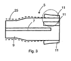
- the bolt holder 5 has several, for example four, six, or any other number of longitudinal slots the longitudinal axis of the stud holder 5 and thus the longitudinal axis of the stud welding head 1 on that from the front end of the head up to a third Half or more of the bolt holder 5 are sufficient. Through this e.g. four Longitudinal slots 7 is the bolt holder 5 in several, for example four, slats 9 divided.
- the bolt holder 5 has one or more strain gauges 11 on that act as a sensor device.
- the strain gauges 11 are here advantageously due to the greatest deformation occurring a bolt movement arranged with the bolt holder 5.
- the strain gauges 11 on the outer surface of the bolt holder 5 arranged in the area of the foot ends of the slots 7, since here with the greatest deformation is to be expected.
- a strain gauge 11 can be fixed with the Outer surface of the bolt holder 5, e.g.
- Fig. 2 shows the state of a bolt holder 5, which with a bolt 15th loaded and for welding the stud 15 to a workpiece 17th ready.
- the bolt 15 was by means of a charging pin 17 from the base of the bolt holder 5 up to its tip in its end position shown in Fig. 2 transported, the lamellae 9 of the bolt holder 5 depending on the time of movement of the bolt 15 and its location in the bolt holder 5 a deformation subject radially outwards until the bolt 15 reaches its end position and acted upon radially inward by a force from the fins of the bolt holder 5 is and possibly additionally by a charging pin 17 against slipping back is held.
- FIG. 3 shows an enlarged individual illustration of the front and middle area a bolt holder 5 from line I in Fig. 2.
- a bridge circuit with the strain gauge or strain gauges serves as variable resistors in the bridge branches, so that when there is a fixed voltage on one diagonal branch, the measuring signal on the other diagonal branch serves as measuring voltage U B can be removed.
- a circuit described is only an example of many conversion or evaluation circuits known to a person skilled in the art, such as, for example, threshold value circuits, analog-digital circuits with a comparator or the like.
- the bolt covers a distance S 1 from time t 1 to time t 2 , this movement being shown in the diagram only as an example as a linear, uniform movement.
- the zero point of the movement is defined here as the point at which the bolt in the bolt holder causes a first movement of the slats 9 outwards.
- the measurement signal of the strain gauges is present as a constant value, for example, as shown in FIG. 4, as a diagonal voltage U 1 of a measuring bridge.
- the measurement voltage U B changes in this area due to the deformation of the lamellae 9 acting on the strain gauge 11 and runs, for example, along a curve 19 shown as a solid line in the diagram according to FIG. 4 up to a point in time t 2 there is no further change in the deformation of the slats 9 and is reached as the final tension U 2 .
- this can correspond to the end position of the bolt 15 in the bolt holder 5 or can already be achieved beforehand by lack of further deformation due to the longitudinal movement of the bolt 15 in the bolt holder 5.
- the solid curve 19 in the diagram according to FIG. 4 shows an example of a bolt 15 without a collar, so that the final tension U 2 is also the maximum of the curve.
- the curve 21 shown in dashed lines in FIG. 4 shows a typical curve profile of a movement of a collar bolt 15 through a bolt holder 5, in which the final value U 2 of the measurement voltage U B is previously exceeded by a maximum U 3 . This maximum is brought about by the larger outer circumference of the collar compared to the remaining circumference of the bolt and the fins 9 which are thereby pushed further radially outwards.
- the course of the curve over time can form the basis for statements such as shape, length, dimension, profile of the bolt 15 in addition to the simple Detect "Pin present yes - no".
- a comparison of an actual curve measured in this way with a target curve be made the actual curve within certain tolerances can lie.
- the target curve can be externally integrated into an evaluation unit e.g. about a terminal, reading device such as Diskette etc. can be entered and / or be determined by means of calibration measurements.
Claims (10)
- Dispositif de retenue de goujon pour un dispositif de soudage de goujons, caractérisé en ce que le dispositif (5) de retenue de goujon comporte un dispositif de détection (11) servant à détecter la présence d'une pièce à souder (15) dans le dispositif de retenue de goujon dans la position de soudage.
- Dispositif de retenue de goujon selon la revendication 1, caractérisé en ce que le dispositif de détection (11) est intégré de façon fixe intérieurement, extérieurement ou dans le dispositif de retenue de goujon (5).
- Dispositif de retenue de goujon selon la revendication 1, caractérisé en ce que le dispositif de détection (11) est disposé de façon amovible et de manière à pouvoir être fixé intérieurement sur, extérieurement sur ou dans le dispositif (5) de retenue de goujon.
- Dispositif de retenue de goujon selon l'une des revendications précédentes, caractérisé en ce que le dispositif de détection (11) est agencé sous la forme d'au moins une jauge extensométrique (11).
- Dispositif de retenue de goujon selon l'une des revendications précédentes, caractérisé en ce que le dispositif de détection (11) est relié à un dispositif d'évaluation et de commande afin de commander le procédé de soudage en fonction des résultats de mesure.
- Dispositif de retenue de goujon selon la revendication 5, caractérisé en ce que le dispositif de détection (11) est relié à un dispositif de mémoire pour mémoriser des résultats de mesure et/ou appeler des résultats de mesure mémorisés.
- Dispositif de soudage de goujons comportant un dispositif de retenue de goujon (5) selon l'une des revendications précédentes.
- Procédé de soudage de goujons comportant un dispositif de soudage de goujons selon la revendication 7, caractérisé en ce que le déroulement du procédé est commandé en fonction du résultat de mesure du dispositif de détection (11).
- Procédé selon la revendication 8, caractérisé en ce que l'allure d'une courbe de mesure (courbe réelle) d'un goujon à souder est comparée à une courbe de consigne de mesure pouvant être prédéterminée, de manière à obtenir des indications concernant le processus de soudage, notamment sur la pièce à souder (15).
- Procédé selon la revendication 9, caractérisé en ce que la courbe de consigne de mesure est obtenue à l'aide d'une ou de plusieurs mesures de calibrage.
Applications Claiming Priority (5)
| Application Number | Priority Date | Filing Date | Title |
|---|---|---|---|
| DE10018239 | 2000-04-12 | ||
| DE10018239A DE10018239C1 (de) | 2000-04-12 | 2000-04-12 | Schweißachse für einen Bolzenschweißkopf mit einer steuerbaren Antriebseinrichtung für einen Ladestift |
| DE2000135371 DE10035371A1 (de) | 2000-07-20 | 2000-07-20 | Bolzenschweißvorrichtung, insbesondere für das Bolzenschweißen ohne Stützfuß |
| DE10035371 | 2000-07-20 | ||
| PCT/DE2001/001253 WO2001076800A1 (fr) | 2000-04-12 | 2001-04-03 | Dispositif de soudage de goujons, notamment destine au soudage de goujon sans pied d'appui |
Publications (2)
| Publication Number | Publication Date |
|---|---|
| EP1272307A1 EP1272307A1 (fr) | 2003-01-08 |
| EP1272307B1 true EP1272307B1 (fr) | 2004-08-04 |
Family
ID=26005291
Family Applications (1)
| Application Number | Title | Priority Date | Filing Date |
|---|---|---|---|
| EP01929297A Expired - Lifetime EP1272307B1 (fr) | 2000-04-12 | 2001-04-03 | Dispositif de soudage de goujons, notamment destine au soudage de goujon sans pied d'appui |
Country Status (5)
| Country | Link |
|---|---|
| EP (1) | EP1272307B1 (fr) |
| AT (1) | ATE272460T1 (fr) |
| AU (1) | AU2001256132A1 (fr) |
| DE (2) | DE50103114D1 (fr) |
| WO (1) | WO2001076800A1 (fr) |
Families Citing this family (10)
| Publication number | Priority date | Publication date | Assignee | Title |
|---|---|---|---|---|
| DE10124088A1 (de) * | 2001-05-16 | 2002-11-21 | Nelson Bolzenschweis Technik G | Verfahren zur Überwachung des Schweißvorgangs beim Bolzenschweißen und Vorrichtung zur Durchführung des Verfahrens |
| DE10220560A1 (de) * | 2002-05-03 | 2003-11-13 | Newfrey Llc | Vorrichtung zum Schweißen von Metallelementen auf Bauteile |
| DE10229690B4 (de) | 2002-06-26 | 2010-03-25 | Newfrey Llc, Newark | Vorrichtung und Verfahren zum Kurzzeit-Lichtbogenschweißen |
| DE102004040846B4 (de) * | 2004-08-23 | 2017-08-03 | Newfrey Llc | Schweißvorrichtung |
| DE102005044367A1 (de) | 2005-09-09 | 2007-03-15 | Newfrey Llc, Newark | Fügesystemkopf, Fügesystem und Verfahren zum Zuführen und Fügen von Elementen |
| DE102010013913B4 (de) * | 2010-04-01 | 2012-01-12 | Newfrey Llc | Fügeverfahren und Fügevorrichtung |
| DE102013227132B3 (de) * | 2013-12-23 | 2015-02-05 | Bolzenschweißtechnik Heinz Soyer GmbH | Schweißvorrichtung sowie Verfahren zum Aufschweißen eines Schweißelements auf ein Werkstück |
| DE102014212735A1 (de) | 2014-07-01 | 2016-01-21 | Bayerische Motoren Werke Aktiengesellschaft | Verfahren zum Bolzenschweißen und Bolzenschweißanlage |
| CN104917027B (zh) * | 2015-06-05 | 2017-05-31 | 中国石油大学(华东) | 应变片自动焊接粘贴装置 |
| EP3473369B1 (fr) | 2017-10-23 | 2021-06-02 | Newfrey LLC | Procédé de contrôle de la durée de vie restante d'un porte-goujon dans un dispositif de soudage de goujons, et agencement pour mettre en oeuvre le procédé |
Family Cites Families (2)
| Publication number | Priority date | Publication date | Assignee | Title |
|---|---|---|---|---|
| DE3215453C1 (de) * | 1982-04-24 | 1983-07-21 | OBO Bettermann oHG, 5750 Menden | Verfahren und Vorrichtung zum Anschweißen eines Bolzens mittels eines elektrischen Lichtbogenbolzenanschweißgerätes |
| DE4403541C2 (de) * | 1994-02-04 | 1996-12-12 | Trw Nelson Bolzenschweisstechn | Bolzenzuführeinrichtung für eine Bolzenschweißvorrichtung |
-
2001
- 2001-04-03 EP EP01929297A patent/EP1272307B1/fr not_active Expired - Lifetime
- 2001-04-03 DE DE50103114T patent/DE50103114D1/de not_active Expired - Fee Related
- 2001-04-03 AU AU2001256132A patent/AU2001256132A1/en not_active Abandoned
- 2001-04-03 AT AT01929297T patent/ATE272460T1/de not_active IP Right Cessation
- 2001-04-03 WO PCT/DE2001/001253 patent/WO2001076800A1/fr active IP Right Grant
- 2001-04-03 DE DE20105789U patent/DE20105789U1/de not_active Expired - Lifetime
Also Published As
| Publication number | Publication date |
|---|---|
| DE50103114D1 (de) | 2004-09-09 |
| EP1272307A1 (fr) | 2003-01-08 |
| AU2001256132A1 (en) | 2001-10-23 |
| DE20105789U1 (de) | 2001-08-02 |
| WO2001076800A1 (fr) | 2001-10-18 |
| ATE272460T1 (de) | 2004-08-15 |
Similar Documents
| Publication | Publication Date | Title |
|---|---|---|
| EP1412125B1 (fr) | Procede de soudage a l'arc de courte duree et systeme de soudage a l'arc de courte duree, permettant de detecter des defauts de haute frequence | |
| EP0335010B1 (fr) | Appareil de soudure électrique pour auto-soudure d'un raccord à spirale chauffante | |
| EP1272307B1 (fr) | Dispositif de soudage de goujons, notamment destine au soudage de goujon sans pied d'appui | |
| EP0108857A2 (fr) | Mandrin de serrage actionné mécaniquement | |
| EP3345707A1 (fr) | Procédé de détermination de manière automatique des dimensions géométriques d'un outil dans une machine à tailler les engrenages | |
| WO2005002774A1 (fr) | Procede et dispositif pour souder par pression en tenant compte des ecarts de longueur des pieces | |
| DE3843450C2 (fr) | ||
| DE3715905C2 (fr) | ||
| DE3227089C2 (de) | Gerät zur Längenmessung | |
| EP1392466B1 (fr) | Procede de controle du processus de soudage lors du soudage de goujons et dispositif de mesure et de depouilement destine a la mise en oeuvre de ce procede | |
| EP0542113B1 (fr) | Mandrin de serrage | |
| DE3013378C2 (de) | Einrichtung zur adaptiven Regelung von Bearbeitungsprozessen an Schleifmaschinen, insbesondere an Rundschleifmaschinen | |
| DE2711862C2 (fr) | ||
| DE2931273C2 (de) | Vorrichtung zur Prüfung eines Gewindes | |
| EP0476304B1 (fr) | Capteur de température | |
| DE3137878C2 (de) | Überlastsicherung für den Vorschubantrieb an einer Werkzeugmaschine | |
| DE102008054251B3 (de) | Verfahren zur Überwachung der Anlage bei einem Werkzeughalter | |
| EP1232032B1 (fr) | Procede pour l'usinage par enlevement de copeaux de pieces electroconductrices | |
| DE10035371A1 (de) | Bolzenschweißvorrichtung, insbesondere für das Bolzenschweißen ohne Stützfuß | |
| AT518422B1 (de) | Speicherbehältnis für eine Formgebungsmaschine | |
| EP1358961A2 (fr) | Dispositif de soudage de goujons | |
| DE4314528C2 (de) | Verfahren zur Überwachung des Schweißvorgangs beim Bolzenschweißen und Vorrichtung zur Durchführung des Verfahrens | |
| EP0255635A2 (fr) | Procédé et dispositif pour étirer une pièce à usiner métallique | |
| EP0204073B1 (fr) | Griffe maintenant une vis avec dispositif pour déterminer (mesurer, vérifier, travailler) la concentricité du filet et de la tige de la vis | |
| DE10331617B4 (de) | Verfahren und Vorrichtung zur Erfassung und Überwachung der Eigenschaften von Komponenten oder Teilen im Sekundärstromkreis von Widerstandsschweißanlagen |
Legal Events
| Date | Code | Title | Description |
|---|---|---|---|
| PUAI | Public reference made under article 153(3) epc to a published international application that has entered the european phase |
Free format text: ORIGINAL CODE: 0009012 |
|
| 17P | Request for examination filed |
Effective date: 20020913 |
|
| AK | Designated contracting states |
Kind code of ref document: A1 Designated state(s): AT BE CH CY DE DK ES FI FR GB GR IE IT LI LU MC NL PT SE TR |
|
| AX | Request for extension of the european patent |
Free format text: AL;LT;LV;MK;RO;SI |
|
| GRAP | Despatch of communication of intention to grant a patent |
Free format text: ORIGINAL CODE: EPIDOSNIGR1 |
|
| GRAS | Grant fee paid |
Free format text: ORIGINAL CODE: EPIDOSNIGR3 |
|
| GRAA | (expected) grant |
Free format text: ORIGINAL CODE: 0009210 |
|
| AK | Designated contracting states |
Kind code of ref document: B1 Designated state(s): AT BE CH CY DE DK ES FI FR GB GR IE IT LI LU MC NL PT SE TR |
|
| PG25 | Lapsed in a contracting state [announced via postgrant information from national office to epo] |
Ref country code: IT Free format text: LAPSE BECAUSE OF FAILURE TO SUBMIT A TRANSLATION OF THE DESCRIPTION OR TO PAY THE FEE WITHIN THE PRESCRIBED TIME-LIMIT;WARNING: LAPSES OF ITALIAN PATENTS WITH EFFECTIVE DATE BEFORE 2007 MAY HAVE OCCURRED AT ANY TIME BEFORE 2007. THE CORRECT EFFECTIVE DATE MAY BE DIFFERENT FROM THE ONE RECORDED. Effective date: 20040804 Ref country code: IE Free format text: LAPSE BECAUSE OF FAILURE TO SUBMIT A TRANSLATION OF THE DESCRIPTION OR TO PAY THE FEE WITHIN THE PRESCRIBED TIME-LIMIT Effective date: 20040804 Ref country code: FI Free format text: LAPSE BECAUSE OF FAILURE TO SUBMIT A TRANSLATION OF THE DESCRIPTION OR TO PAY THE FEE WITHIN THE PRESCRIBED TIME-LIMIT Effective date: 20040804 Ref country code: TR Free format text: LAPSE BECAUSE OF FAILURE TO SUBMIT A TRANSLATION OF THE DESCRIPTION OR TO PAY THE FEE WITHIN THE PRESCRIBED TIME-LIMIT Effective date: 20040804 Ref country code: NL Free format text: LAPSE BECAUSE OF FAILURE TO SUBMIT A TRANSLATION OF THE DESCRIPTION OR TO PAY THE FEE WITHIN THE PRESCRIBED TIME-LIMIT Effective date: 20040804 |
|
| REG | Reference to a national code |
Ref country code: GB Ref legal event code: FG4D Free format text: NOT ENGLISH |
|
| REG | Reference to a national code |
Ref country code: CH Ref legal event code: EP |
|
| REG | Reference to a national code |
Ref country code: IE Ref legal event code: FG4D Free format text: GERMAN |
|
| REF | Corresponds to: |
Ref document number: 50103114 Country of ref document: DE Date of ref document: 20040909 Kind code of ref document: P |
|
| PG25 | Lapsed in a contracting state [announced via postgrant information from national office to epo] |
Ref country code: GR Free format text: LAPSE BECAUSE OF FAILURE TO SUBMIT A TRANSLATION OF THE DESCRIPTION OR TO PAY THE FEE WITHIN THE PRESCRIBED TIME-LIMIT Effective date: 20041104 Ref country code: SE Free format text: LAPSE BECAUSE OF FAILURE TO SUBMIT A TRANSLATION OF THE DESCRIPTION OR TO PAY THE FEE WITHIN THE PRESCRIBED TIME-LIMIT Effective date: 20041104 Ref country code: DK Free format text: LAPSE BECAUSE OF FAILURE TO SUBMIT A TRANSLATION OF THE DESCRIPTION OR TO PAY THE FEE WITHIN THE PRESCRIBED TIME-LIMIT Effective date: 20041104 |
|
| PG25 | Lapsed in a contracting state [announced via postgrant information from national office to epo] |
Ref country code: ES Free format text: LAPSE BECAUSE OF FAILURE TO SUBMIT A TRANSLATION OF THE DESCRIPTION OR TO PAY THE FEE WITHIN THE PRESCRIBED TIME-LIMIT Effective date: 20041115 |
|
| GBT | Gb: translation of ep patent filed (gb section 77(6)(a)/1977) |
Effective date: 20041208 |
|
| NLV1 | Nl: lapsed or annulled due to failure to fulfill the requirements of art. 29p and 29m of the patents act | ||
| LTIE | Lt: invalidation of european patent or patent extension |
Effective date: 20040804 |
|
| REG | Reference to a national code |
Ref country code: IE Ref legal event code: FD4D |
|
| PG25 | Lapsed in a contracting state [announced via postgrant information from national office to epo] |
Ref country code: AT Free format text: LAPSE BECAUSE OF NON-PAYMENT OF DUE FEES Effective date: 20050403 Ref country code: LU Free format text: LAPSE BECAUSE OF NON-PAYMENT OF DUE FEES Effective date: 20050403 Ref country code: CY Free format text: LAPSE BECAUSE OF FAILURE TO SUBMIT A TRANSLATION OF THE DESCRIPTION OR TO PAY THE FEE WITHIN THE PRESCRIBED TIME-LIMIT Effective date: 20050403 |
|
| PG25 | Lapsed in a contracting state [announced via postgrant information from national office to epo] |
Ref country code: BE Free format text: LAPSE BECAUSE OF NON-PAYMENT OF DUE FEES Effective date: 20050430 Ref country code: CH Free format text: LAPSE BECAUSE OF NON-PAYMENT OF DUE FEES Effective date: 20050430 Ref country code: MC Free format text: LAPSE BECAUSE OF NON-PAYMENT OF DUE FEES Effective date: 20050430 Ref country code: LI Free format text: LAPSE BECAUSE OF NON-PAYMENT OF DUE FEES Effective date: 20050430 |
|
| PLBE | No opposition filed within time limit |
Free format text: ORIGINAL CODE: 0009261 |
|
| STAA | Information on the status of an ep patent application or granted ep patent |
Free format text: STATUS: NO OPPOSITION FILED WITHIN TIME LIMIT |
|
| ET | Fr: translation filed | ||
| 26N | No opposition filed |
Effective date: 20050506 |
|
| BERE | Be: lapsed |
Owner name: *NELSON BOLZENSCHWEISS-TECHNIK G.M.B.H. & CO. K.G. Effective date: 20050430 |
|
| REG | Reference to a national code |
Ref country code: CH Ref legal event code: PL |
|
| BERE | Be: lapsed |
Owner name: *NELSON BOLZENSCHWEISS-TECHNIK G.M.B.H. & CO. K.G. Effective date: 20050430 |
|
| PG25 | Lapsed in a contracting state [announced via postgrant information from national office to epo] |
Ref country code: PT Free format text: LAPSE BECAUSE OF NON-PAYMENT OF DUE FEES Effective date: 20050104 |
|
| PGFP | Annual fee paid to national office [announced via postgrant information from national office to epo] |
Ref country code: DE Payment date: 20090420 Year of fee payment: 9 Ref country code: FR Payment date: 20090417 Year of fee payment: 9 |
|
| PGFP | Annual fee paid to national office [announced via postgrant information from national office to epo] |
Ref country code: GB Payment date: 20090408 Year of fee payment: 9 |
|
| GBPC | Gb: european patent ceased through non-payment of renewal fee |
Effective date: 20100403 |
|
| REG | Reference to a national code |
Ref country code: FR Ref legal event code: ST Effective date: 20101230 |
|
| PG25 | Lapsed in a contracting state [announced via postgrant information from national office to epo] |
Ref country code: DE Free format text: LAPSE BECAUSE OF NON-PAYMENT OF DUE FEES Effective date: 20101103 |
|
| PG25 | Lapsed in a contracting state [announced via postgrant information from national office to epo] |
Ref country code: GB Free format text: LAPSE BECAUSE OF NON-PAYMENT OF DUE FEES Effective date: 20100403 |
|
| PG25 | Lapsed in a contracting state [announced via postgrant information from national office to epo] |
Ref country code: FR Free format text: LAPSE BECAUSE OF NON-PAYMENT OF DUE FEES Effective date: 20100430 |