EP1271969A2 - Signaling gateway system and network management method - Google Patents
Signaling gateway system and network management method Download PDFInfo
- Publication number
- EP1271969A2 EP1271969A2 EP02013719A EP02013719A EP1271969A2 EP 1271969 A2 EP1271969 A2 EP 1271969A2 EP 02013719 A EP02013719 A EP 02013719A EP 02013719 A EP02013719 A EP 02013719A EP 1271969 A2 EP1271969 A2 EP 1271969A2
- Authority
- EP
- European Patent Office
- Prior art keywords
- signaling
- network
- network management
- signaling gateway
- gateways
- Prior art date
- Legal status (The legal status is an assumption and is not a legal conclusion. Google has not performed a legal analysis and makes no representation as to the accuracy of the status listed.)
- Withdrawn
Links
- 230000011664 signaling Effects 0.000 title claims abstract description 142
- 238000007726 management method Methods 0.000 title claims description 74
- 238000006243 chemical reaction Methods 0.000 abstract description 2
- 238000010586 diagram Methods 0.000 description 6
- 239000002699 waste material Substances 0.000 description 2
- 238000004891 communication Methods 0.000 description 1
- 238000010276 construction Methods 0.000 description 1
- 238000009434 installation Methods 0.000 description 1
- 238000000034 method Methods 0.000 description 1
Images

Classifications
-
- H—ELECTRICITY
- H04—ELECTRIC COMMUNICATION TECHNIQUE
- H04Q—SELECTING
- H04Q3/00—Selecting arrangements
- H04Q3/0016—Arrangements providing connection between exchanges
- H04Q3/0062—Provisions for network management
-
- H—ELECTRICITY
- H04—ELECTRIC COMMUNICATION TECHNIQUE
- H04Q—SELECTING
- H04Q3/00—Selecting arrangements
- H04Q3/0016—Arrangements providing connection between exchanges
- H04Q3/0025—Provisions for signalling
Definitions
- the present invention relates to a signaling gateway system and a network management method for use in the signaling gateway system.
- this invention relates to a network management method for use in distributed signaling gateways.
- An existing signaling gateway systems comprises a plurality of gateways which are connected and distributed between a signal network of a telephone network and an Internet protocol network.
- Each of the signaling gateways carries out a network management control to realize an inter-working of a signaling message between the signal network and an application server on the Internet protocol network.
- each network management unit is limited to within a range of a line or circuit (of the signal network) received in each signaling gateway, while each signaling gateway has its quality maintained within its exactly realizable range.
- a signaling gateway system for realizing an inter-working of signaling message between a signal network of a telephone network and an application server of an Internet protocol network.
- this signaling gateway system comprises a plurality of signaling gateways connected and distributed between the signal network and the Internet protocol network for transferring the signaling message between the signal network and the Internet protocol network.
- a network management server connected to the signaling gateways for performing a centralized network management between the signal network and the Internet protocol network.
- a network management method for use in a signaling gateway system realizing an inter-working of a signaling message between a signal network of a telephone network and an application server of an Internet protocol network.
- this network management method comprises using a plurality of signaling gateways connected and distributed between the signal network and the Internet protocol network to transfer a signaling message between the signal network and the Internet protocol; and using a network management server connected to the signaling gateways to perform a centralized network management between the signal network and the Internet protocol network.
- Fig. 1 is a block diagram showing a signaling gateway system formed according to the preferred embodiment of the invention.
- a signaling gateway system (SGSYS) 1 comprises a network management server 10 located on an Internet protocol (IP) network 100, and a plurality of signaling gateways (SG) 20 to 2n connected and distributed between the IP network 100 and a signaling network 200.
- the network management server 10 is connected to the signaling gateways 20 to 2n through the IP network 100 or control lines (not shown),
- SS7 Signaling System No. 7: common line signaling manner
- AS application servers
- the signal network 200 is provided to transfer signaling messages within a telephone network, while the application servers 30 to 3k are provided such that a signaling message can be terminated on the IP network 100 so as to realize an application processing such as calling. In this way, it is possible to realize an inter-working of signaling messages between the signal network 200 on one hand and the application servers 30 to 3k on the other.
- an actual network (of the IP network 100) also includes a network device (not shown) such as a router which is disposed between the application servers 30 to 3K on one hand and the signaling gateway system 1 on the other, such a network device and its installation will not be described in the present specification since they are well known in the art and are not directly related to the present invention.
- a network device such as a router which is disposed between the application servers 30 to 3K on one hand and the signaling gateway system 1 on the other, such a network device and its installation will not be described in the present specification since they are well known in the art and are not directly related to the present invention.
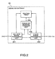
- Fig. 2 is a block diagram showing in detail the signaling gateway 20 illustrated in Fig. 1.
- the signaling gateway 20 comprises No. 7 side signal processing unit 201, an IP side signal processing unit 202, a signaling message transfer unit 203, and a routing table 204 for storing routing information.
- each of the signaling gateways 21 to 2n has the same construction as that of the signaling gateway 20.
- the signaling message transfer unit 203 is provided to perform a transport layer control for transferring a signaling message, a signaling message routing between the link of circuits 210 to 21n (using a routing table 204) on one hand and the associations 110 to 11m as well as the above stream on the other, and a transport protocol conversion for transferring signaling message.
- a transport layer control for transferring a signaling message
- a signaling message routing between the link of circuits 210 to 21n using a routing table 204
- the associations 110 to 11m as well as the above stream on the other
- a transport protocol conversion for transferring signaling message.
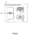
- Fig. 3 is a block diagram showing a network management server 10 illustrated in Fig. 1.
- the network management server 10 comprises a signal processing unit 11, a network centralized management and control unit 12, and a routing table control unit 13 for setting and controlling the routing information stored in the routing table 204.
- the network centralized management and control unit 12 of the network management server 10 performs a network centralized management and control of the signaling link received in the signaling gateways 20 to 2n.
- the network management server 10 controls transferring the signaling message between the signal network 100 and application servers 30 to 3k on the IP network 200.
- the network management server 10 performs the network centralized management without cooperation of the application servers 30 to 3k. That is, the application servers 30 to 3k does not have network management functions specified in the signal network in this embodiment.
- the routing table control unit 13 operates, in accordance with the network management results of the network centralized management and control unit 12, to perform setting and management of the routing information stored in each routing table 204 of the signaling gateways 20 to 2n, so as to realize a routing between the link (on the circuits 210 to 21n through the signaling gateways 20 to 2n) and the associations 110 to 11n as well as the stream.
- the network management server 10 it is possible for the network management server 10 to provide a high reliability, thereby ensuring an improved network management function.
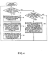
- Fig. 4 is a flowchart for describing an operation of the network management server 10 illustrated in Fig. 1.
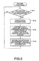
- Fig. 5 is another flowchart for describing an operation of the signaling gateways 20 to 2n illustrated in Fig. 1. In the following, an operation of the signaling gateway system 1 according to the preferred embodiment of the present invention will be described with reference to Figs. 1 to 5.
- the gateway 20 detects the failure and produces a circuit failure report to inform the network management server 10 about occurrence of the failure on the circuit 210.
- the network management server 10 is provided such that when the circuit 210 received in the signaling gateway 20 has the failure (step S1 shown in Fig. 4), this network management server 10 operates, in accordance with the circuit failure report from the signaling gateway 20, to recognize a fact that a signaling massage transfer (through the application server 30, the association 110, the signaling gateway 20 and the circuit 210) has already been impossible (step S2 shown in Fig. 4).
- the network management server 10 does not use the circuit 210 with respect to the signal network 200 through the signaling gateway 20, but carries out a signaling link change-over control prescribed by a signal message transfer control, in which a signaling message is transferred in detour to the circuit 211 received in the signaling gateway 21 which has established the application server 30 and a spare association 111 (step S3 shown in Fig. 4).
- the network management server 10 by releasing the association 110 in connection with the application server 30 with respect to the signaling gateway 20, operates to indicate that the signaling gateway 20 has become unable to communicate with the signal network 200 (with respect to the application server 30), and that a communication is performed with the signal network 200 by employing a spare association 111 and the signaling gateway SG 21 (step 4 shown in Fig. 4).
- the signaling message to the signal network 200 received and buffered by the signaling gateway 20 is transferred to the signal network 200, by way of the IP network 100 and through the signaling gateway 21, thereby preventing a message loss which is often associated with the change-over operation.
- the network management server 10 is provided such that as soon as the circuit 210 is restored (step S5 shown in Fig. 4), this network management server 10 performs the change-back operation for restoring signaling message transfer using the signaling gateway 20, the circuit 210 and the association 110 (step S6 shown in Fig. 4).
- the signaling gateways 20 to 2n operate in a manner such that as soon as failures occur in the application servers 30 to 3k or the associations 110 to 11m (step S11 shown in Fig. 5), these signaling gateways perform an association change-over (step S12 shown in Fig. 5).
- the application server 30 is an active (ACT) server of the signaling gateway 20 and the application server 3k is a standby (SBY) server
- the signaling gateway 20 operates to change a signaling message transfer route to the association 11m-1 in connection with the application server 3k, thereby ensuring the continuation of the service (step S13 shown in Fig. 5).
- the signaling gateway 20 will inform the network management server 10 of a change in the routing information (step 14 shown in Fig. 5).
- the signaling gateway system 1 can be established which realizes an inter-working of signaling message between the signal network 200 of the telephone network and the application servers 30 to 3k of the IP network 100. Further, a signaling message transfer function acting between the signal network 200 and the IP network 100 can be assigned to the distributed signaling gateways 20 to 2n. In addition, a network management/control function of the signal network 200 received in the distributed signaling gateways 20 to 2n can be assigned to the network management server 10 having a high reliability. As a result, it is possible to obtain an improved reliability for the network management of the entire signaling gateway system 1.
- the network management server 10 executes the centralized network management in the signaling gateway system 1, when failures occur in the respective signaling gateways 20 to 2n, it is possible to perform the change-over/back control extending the signaling gateways 20 to 2n, using the network management server 10. In this way, it is possible to obtain an improved reliability in dealing with failures occurring in the links of the respective signaling gateways 20 to 2n and the signal network 200.
- the signaling gateway system 1 by virtue of a connection among the signaling gateways 20 to 2n and through the IP network 100 which is mainly controlled by the network management server 10, it is possible to perform a control for preventing a message loss at the time of change-over, and to support functions which could not be supported when the signaling gateways 20 to 2n are set independent from one another.
- the signaling gateways 20 to 2n are released from the network management, it is possible for them to be specified in the signaling message transfer and thus increase the transfer ability. As a result, it becomes possible to effectively use the circuits 210 to 21 n in connection with the signal network 200.
Landscapes
- Engineering & Computer Science (AREA)
- Computer Networks & Wireless Communication (AREA)
- Data Exchanges In Wide-Area Networks (AREA)
- Telephonic Communication Services (AREA)
Abstract
Description
Claims (10)
- A signaling gateway system realizing an inter-working of a signaling message between a signal network of a telephone network and an application server of an Internet protocol network, said signaling gateway system comprising:a plurality of signaling gateways connected and distributed between said signal network and said Internet protocol network for transferring said signaling message between said signal network and said application server; anda network management server connected to said signaling gateways for performing a centralized network management between said signal network and said Internet protocol network.
- A signaling gateway system as claimed in claim 1, wherein each of said gateways comprises a routing table for storing routing information,
said network management server comprising a routing table control unit for controlling said routing table. - A signaling gateway system as claimed in claim 1, wherein said network management server is formed in a manner such that when any one of said signaling gateways detects a failure, said network management server performs a change-over control from the signaling gateway which detects said failure to another one of said signaling gateways.
- A signaling gateway system as claimed in claim 3, wherein said network management server is further formed in a manner such that when the signaling gateway which detects said failure further detects restoration from said failure, said network management server performs a change-back control from the other one of signaling gateways to the signaling gateway which detects restoration.
- A signaling gateway system as claimed in claim 3, wherein said network management server is formed so as to transfer said signaling message received by the signaling gateway which detects said failure to the other signaling gateway through said Internet protocol network.
- A signaling gateway system as claimed in claim 1, wherein said network management server is formed so as to performs said centralized network management without cooperation of the application servers.
- A network management method for use in a signaling gateway system realizing an inter-working of a signaling message between a signal network of a telephone network and an application server of an Internet protocol network, said network management method comprising the steps of:using a plurality of signaling gateways connected and distributed between said signal network and said Internet protocol network to transfer a signaling message between said signal network and said Internet protocol network; andusing a network management server connected to said signaling gateways to perform a centralized network management between said signal network and said Internet Protocol network .
- A network management method as claimed in claim 7, wherein the using step of said network management server comprises a step which is carried out at the time any one of said signaling gateways detects a failure, to perform a change-over control from the signaling gateway which detects said failure to another one of said signaling gateways.
- A network management method as claimed in claim 8, wherein the using step of said network management server further comprises a step of transferring said signaling message received by the signaling gateway which detects said failure to the other signaling gateway through said Internet protocol network.
- A network management method as claimed in claim 7, wherein the using step of said network management server are performed without cooperation of the application servers.
Applications Claiming Priority (2)
| Application Number | Priority Date | Filing Date | Title |
|---|---|---|---|
| JP2001185702A JP3666415B2 (en) | 2001-06-20 | 2001-06-20 | Signaling gateway system and network management method used therefor |
| JP2001185702 | 2001-06-20 |
Publications (2)
| Publication Number | Publication Date |
|---|---|
| EP1271969A2 true EP1271969A2 (en) | 2003-01-02 |
| EP1271969A3 EP1271969A3 (en) | 2003-05-21 |
Family
ID=19025240
Family Applications (1)
| Application Number | Title | Priority Date | Filing Date |
|---|---|---|---|
| EP02013719A Withdrawn EP1271969A3 (en) | 2001-06-20 | 2002-06-20 | Signaling gateway system and network management method |
Country Status (6)
| Country | Link |
|---|---|
| US (1) | US20030021293A1 (en) |
| EP (1) | EP1271969A3 (en) |
| JP (1) | JP3666415B2 (en) |
| CN (1) | CN1392714A (en) |
| BR (1) | BR0203378A (en) |
| CA (1) | CA2391175A1 (en) |
Cited By (2)
| Publication number | Priority date | Publication date | Assignee | Title |
|---|---|---|---|---|
| EP1519591A1 (en) * | 2003-09-26 | 2005-03-30 | Hewlett-Packard Development Company, L.P. | Methods and apparatus for controlling signalling gateways |
| CN1889610B (en) * | 2005-12-13 | 2010-05-05 | 华为技术有限公司 | Large-capacity distributed signaling processing device and method thereof |
Families Citing this family (12)
| Publication number | Priority date | Publication date | Assignee | Title |
|---|---|---|---|---|
| CN100337459C (en) * | 2003-06-24 | 2007-09-12 | 华为技术有限公司 | Method for processing user message with wrong interface identifier |
| CN1317850C (en) * | 2003-06-24 | 2007-05-23 | 华为技术有限公司 | A method for handling business interruption |
| US8363637B2 (en) * | 2004-06-30 | 2013-01-29 | Movius Interactive Inc. | Telephony protocol server and telephony protocol client in a distributed IP architecture telecommunications system |
| US20060002403A1 (en) * | 2004-06-30 | 2006-01-05 | Glenayre Electronics, Inc. | Distributed IP architecture for telecommunications system |
| US7701929B2 (en) * | 2004-06-30 | 2010-04-20 | Movius Interactive | Distributed telecommunications architecture providing redundant gateways and IP device integration |
| DE602005009139D1 (en) * | 2005-03-29 | 2008-10-02 | Hewlett Packard Development Co | Router with special features |
| US20070202927A1 (en) * | 2006-02-28 | 2007-08-30 | Pfleging Gerald W | Automated search and rescue call generation to mobile phones in a defined geographic disaster area |
| WO2009104493A1 (en) * | 2008-02-19 | 2009-08-27 | 日本電気株式会社 | Gateway device, communication system, and communication method |
| JPWO2010064532A1 (en) | 2008-12-02 | 2012-05-10 | 日本電気株式会社 | Communication network management system, method, program, and management computer |
| WO2010064531A1 (en) * | 2008-12-02 | 2010-06-10 | 日本電気株式会社 | Communication network management system, method and program, and management calculator |
| JP5888408B2 (en) * | 2012-04-27 | 2016-03-22 | 日本電気株式会社 | COMMUNICATION SYSTEM, ROUTE CONTROL METHOD, AND ROUTE CONTROL DEVICE |
| US12235964B2 (en) | 2020-09-25 | 2025-02-25 | Ati Technologies Ulc | Secure collection and communication of computing device working data |
Family Cites Families (9)
| Publication number | Priority date | Publication date | Assignee | Title |
|---|---|---|---|---|
| CA2044718C (en) * | 1990-06-18 | 1998-07-28 | Katsumi Omuro | Rerouting and change-back systems for asynchronous transfer mode network |
| SE515761C2 (en) * | 1998-06-03 | 2001-10-08 | Ericsson Telefon Ab L M | Device, system and method related to data / telecommunications to manage information about communication paths between process means |
| US6556547B1 (en) * | 1998-12-15 | 2003-04-29 | Nortel Networks Limited | Method and apparatus providing for router redundancy of non internet protocols using the virtual router redundancy protocol |
| US6754220B1 (en) * | 1999-05-31 | 2004-06-22 | International Business Machines Corporation | System and method for dynamically assigning routers to hosts through a mediator |
| JP2002084363A (en) * | 2000-09-06 | 2002-03-22 | Nec Corp | Gateway system and line control method used therefor |
| US6522629B1 (en) * | 2000-10-10 | 2003-02-18 | Tellicent Inc. | Traffic manager, gateway signaling and provisioning service for all packetized networks with total system-wide standards for broad-band applications including all legacy services |
| US6954436B1 (en) * | 2001-02-28 | 2005-10-11 | Extreme Networks, Inc. | Method and apparatus for selecting redundant routers using tracking |
| JP3678161B2 (en) * | 2001-04-11 | 2005-08-03 | 日本電気株式会社 | Gateway system and management management method used therefor |
| US7929420B2 (en) * | 2006-02-02 | 2011-04-19 | Avaya, Inc. | Method and apparatus for learning VRRP backup routers |
-
2001
- 2001-06-20 JP JP2001185702A patent/JP3666415B2/en not_active Expired - Lifetime
-
2002
- 2002-06-19 CA CA002391175A patent/CA2391175A1/en not_active Abandoned
- 2002-06-19 US US10/173,789 patent/US20030021293A1/en not_active Abandoned
- 2002-06-20 EP EP02013719A patent/EP1271969A3/en not_active Withdrawn
- 2002-06-20 BR BR0203378-0A patent/BR0203378A/en not_active IP Right Cessation
- 2002-06-20 CN CN02124826A patent/CN1392714A/en active Pending
Cited By (4)
| Publication number | Priority date | Publication date | Assignee | Title |
|---|---|---|---|---|
| EP1519591A1 (en) * | 2003-09-26 | 2005-03-30 | Hewlett-Packard Development Company, L.P. | Methods and apparatus for controlling signalling gateways |
| WO2005032163A1 (en) * | 2003-09-26 | 2005-04-07 | Hewlett-Packard Development Company, L.P. | Methods and apparatus for controlling signalling gateways |
| US7496087B2 (en) | 2003-09-26 | 2009-02-24 | Hewlett-Packard Development Company, L.P. | Methods and apparatus for controlling signalling gateways |
| CN1889610B (en) * | 2005-12-13 | 2010-05-05 | 华为技术有限公司 | Large-capacity distributed signaling processing device and method thereof |
Also Published As
| Publication number | Publication date |
|---|---|
| EP1271969A3 (en) | 2003-05-21 |
| US20030021293A1 (en) | 2003-01-30 |
| CN1392714A (en) | 2003-01-22 |
| BR0203378A (en) | 2003-04-01 |
| JP2003008663A (en) | 2003-01-10 |
| JP3666415B2 (en) | 2005-06-29 |
| CA2391175A1 (en) | 2002-12-20 |
Similar Documents
| Publication | Publication Date | Title |
|---|---|---|
| US6944280B2 (en) | Gateway system having a redundant structure of media gateway controllers | |
| US7046684B2 (en) | Gateway system and fault management method | |
| US7995564B1 (en) | Geographic redundancy for call servers in a cellular system based on a bearer-independent core network | |
| EP1465440B1 (en) | Method and apparatus for changeover of associations between signalling processes | |
| EP2238782B1 (en) | Mobile core network node redundancy | |
| EP1271969A2 (en) | Signaling gateway system and network management method | |
| US20020156925A1 (en) | Gateway system and integrated management method | |
| US20050207397A1 (en) | Method and communication arrangement for alternately operating a terminal at at least two communication nodes | |
| CN1937782B (en) | Frame device and its message transmitting method | |
| US7079481B2 (en) | Redundant network controller management system | |
| US6243357B1 (en) | Lan emulation system and atm switch | |
| CN100456685C (en) | A L2 multicast implementation method and access device | |
| JP3270409B2 (en) | Traffic diversion method of common channel signal relay network by network management system | |
| US20070016678A1 (en) | Data processing in a signaling gateway | |
| JPH0423555A (en) | Common line signal processing system | |
| JPH086887A (en) | Server connection switching method | |
| KR100321259B1 (en) | Method for preventing call cutting when link error birth in cdma system | |
| KR100350452B1 (en) | Apparatus and method for checking status and routing of voice call process unit in communication network | |
| JP3185758B2 (en) | Logical connection management method | |
| JPS58116840A (en) | Centralized annular type data communication network system | |
| JPH0698008A (en) | Abnormal signal terminal station separating system | |
| JP2000270127A (en) | Inter-station control information transfer system | |
| HK1144871B (en) | Mobile core network node redundancy | |
| WO2005041520A1 (en) | Method and apparatus for backhaul signaling in ip networks |
Legal Events
| Date | Code | Title | Description |
|---|---|---|---|
| PUAI | Public reference made under article 153(3) epc to a published international application that has entered the european phase |
Free format text: ORIGINAL CODE: 0009012 |
|
| AK | Designated contracting states |
Kind code of ref document: A2 Designated state(s): AT BE CH CY DE DK ES FI FR GB GR IE IT LI LU MC NL PT SE TR |
|
| AX | Request for extension of the european patent |
Free format text: AL;LT;LV;MK;RO;SI |
|
| PUAL | Search report despatched |
Free format text: ORIGINAL CODE: 0009013 |
|
| AK | Designated contracting states |
Designated state(s): AT BE CH CY DE DK ES FI FR GB GR IE IT LI LU MC NL PT SE TR |
|
| AX | Request for extension of the european patent |
Extension state: AL LT LV MK RO SI |
|
| 17P | Request for examination filed |
Effective date: 20030410 |
|
| AKX | Designation fees paid |
Designated state(s): DE GB IT |
|
| 17Q | First examination report despatched |
Effective date: 20040503 |
|
| STAA | Information on the status of an ep patent application or granted ep patent |
Free format text: STATUS: THE APPLICATION HAS BEEN WITHDRAWN |
|
| 18W | Application withdrawn |
Effective date: 20040809 |