EP1271959A2 - Video decoding device and method, and program product therefor - Google Patents
Video decoding device and method, and program product therefor Download PDFInfo
- Publication number
- EP1271959A2 EP1271959A2 EP02252700A EP02252700A EP1271959A2 EP 1271959 A2 EP1271959 A2 EP 1271959A2 EP 02252700 A EP02252700 A EP 02252700A EP 02252700 A EP02252700 A EP 02252700A EP 1271959 A2 EP1271959 A2 EP 1271959A2
- Authority
- EP
- European Patent Office
- Prior art keywords
- field
- picture
- video
- repeat
- attribute data
- Prior art date
- Legal status (The legal status is an assumption and is not a legal conclusion. Google has not performed a legal analysis and makes no representation as to the accuracy of the status listed.)
- Ceased
Links
Images







Classifications
-
- H—ELECTRICITY
- H04—ELECTRIC COMMUNICATION TECHNIQUE
- H04N—PICTORIAL COMMUNICATION, e.g. TELEVISION
- H04N19/00—Methods or arrangements for coding, decoding, compressing or decompressing digital video signals
- H04N19/10—Methods or arrangements for coding, decoding, compressing or decompressing digital video signals using adaptive coding
- H04N19/102—Methods or arrangements for coding, decoding, compressing or decompressing digital video signals using adaptive coding characterised by the element, parameter or selection affected or controlled by the adaptive coding
- H04N19/103—Selection of coding mode or of prediction mode
- H04N19/112—Selection of coding mode or of prediction mode according to a given display mode, e.g. for interlaced or progressive display mode
Definitions
- the present invention relates to a video decoding device, a video decoding method, and a program product therefor. More particularly, the present invention relates to a video decoding device which decodes a video stream containing MPEG-compressed picture frames each consisting of first and second fields while inserting extra fields into the video stream in process a specified number of times. The present invention further relates to a video decoding method and a computer program which performs the same.
- MPEG Moving Picture Experts Group
- MPEG-based video coding and decoding systems play an essential role in our multimedia processing environments of today, and various types of MPEG coders and decoders have been developed.
- FIG. 15 shows a typical configuration of a conventional MPEG video decoding device. As seen, this device comprises the following elements: a buffer memory 50, a video decoder 51, a decoding controller 52, a frame memory 53, and a display controller 54 and v-sync generator 55.
- the buffer memory 50 serves as a temporary storage space for buffering an incoming bit stream.
- the video decoder 51 decodes video data stored in the buffer memory 50 in response to a decoding start command given from the decoding controller 52.
- the video data includes: intra-coded pictures (I pictures), predictive-coded pictures (P pictures), and bidirectionally predictive-coded pictures (B pictures).
- the resulting decoded pictures are stored into the frame memory 53.
- the decoding controller 52 controls video decoding processes, including issuance of decoding start commands to the video decoder 51.
- the frame memory 53 has the capacity of four pictures (or four frames), the space of which is segmented into four sections to store individual pictures reproduced by the video decoder 51. Those memory sections are referred to herein as the "banks.”
- the display controller 54 determines the direction of playback operation according to a playback direction flag which indicates whether it is forward playback or reverse playback.
- the display controller 54 also provides the frame memory 53 with display start commands in synchronization with a vertical synchronization (v-sync) signal. Further, the display controller 54 determines in what order to read pictures when displaying a video stream, consulting display parameters stored in the frame memory 53.
- v-sync vertical synchronization
- the buffer memory 50 stores and forwards an incoming bitstream to the video decoder 51.
- the decoding controller 52 issues a decoding start command, which causes the video decoder 51 to reproduce motion pictures by decoding the source bitstream supplied from the buffer memory 50 in accordance with the syntax of MPEG video specifications.
- the resultant decoded pictures are supplied to the frame memory 53 for display.
- various display parameters are also reproduced along with the motion pictures themselves and stored in their relevant parameter banks of the frame memory 53.
- the picture I2 has been decoded and stored into the second bank (bank #2).
- Display parameters for the picture I2 are written into its associated parameter bank #2, which is shown on the right of the bank #2 in FIG. 15.
- four decoded pictures I2, B0, B1, and P3 are stored in the banks #2, #0, #1, and #3, respectively, and their corresponding parameters are stored in the associated parameter areas.
- the display controller 54 operates in synchronization with the v-sync signal supplied from the v-sync generator 55. Upon detection of every falling edge of the v-sync signal, the display controller 54 reads display parameters out of one of the parameter banks relevant to the next picture to be displayed. In forward playback mode, the four pictures should be displayed in the order of B0, B1, I2, and P3, and accordingly, the display controller 54 begins a display process with fetching parameters for the first picture B0. Such parameters describe the intended display format of each picture in the video stream. The display controller 54 uses them to determine how the picture of interest should be presented on a television screen.
- the display controller 54 retrieves picture data from the frame memory 53 for display.
- the display controller 54 reads the data of picture B0 out of the bank #0 and outputs it for display purposes, since the first picture is B0.
- each picture frame is interlaced into two fields called “top field” and "bottom field.”
- the display controller 54 obtains one frame of 704 x 480 pixels by actually reading its top field first and then its bottom field.
- the display controller 54 starts working at the next picture B1. As in the case of picture B0, it first reads relevant parameters out of the parameter bank #1, parses them, and retrieves the picture data of B1 from the bank #1 of the frame memory 53 for display. The display controller 54 processes and outputs the other pictures I2 and P3 just in the same way.
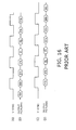
- FIG. 16 is a timing diagram which explains the operation of the known video decoding device of FIG. 15.
- the topmost two rows (A) and (B) of FIG. 16 show a v-sync signal and a sequence of reproduced pictures.
- the sequence starts with the top field of picture B0 (B0t), which is followed by the bottom field of the same (B0b).
- B0t top field of picture
- B0b bottom field of the same
- the lower-case letters "t” and "b” are used to mean “top field” and "bottom field,” respectively.
- the fields of other pictures are read and displayed in the order of: B1t, B1b, I2t, I2b, P3t, and P3b.
- the video decoding device In reverse playback mode, the video decoding device outputs pictures backward.
- the decoding phase of this process is the same as that in the forward playback mode described in (1). That is, the video decoder 51 decodes a given video bitstream and stores the resultant pictures into the frame memory 53.
- the subsequent read operation is different from that in the forward playback mode.
- the display controller 54 makes read access to the frame memory 53 in the reverse order as will be described below.
- the display controller 54 To play back a video in the reverse direction, the display controller 54 has to be so notified. This is accomplished by setting the playback direction flag to "reverse.” Recognizing the requested playback direction from this flag, the display controller 54 starts reading video data in synchronization with the falling edge of the v-sync signal. In the present example, the four pictures are read in the order of P3, I2, B1, and B0, which is the opposite to how they are read out in forward playback mode.
- the display controller 54 uses display parameters also in reverse playback mode, interpreting the parameter "top_field_first” adaptively to the playback direction, More specifically, this parameter "top_field_first” specifies whether to read the top field first ("1") or the bottom field first ("0") in forward playback mode.
- this parameter "top_field_first” specifies whether to read the top field first ("1") or the bottom field first ("0") in forward playback mode.
- top_field_first is set to "1" in reverse playback mode
- the display controller 54 interprets it in the opposite way, thus reading out the bottom field first and then the top field.
- Parts (C) and (D) of FIG. 16 show the v-sync signal and the sequence of pictures I2, B0, B1 and P3 which are produced in the reverse direction according to the above-described rules.
- the sequence starts with P3b, and it is followed by the fields of: P3t, I2b, I2t, B1b, B1t, B0b, and B0t. Note that this order is exactly opposite to that in the forward playback mode.
- a motion picture camera When recording a movie, a motion picture camera captures images at 24 frames every second. Frame rate conversion is therefore required to play a 24-fps motion picture on 30-fps television systems. This is known as the "telecine conversion.” A telecine converter inserts an extra frame every fourth frame to increase the frame rate to 30 fps. The resultant sequence of pictures is referred to as "3:2 pulldown video.” The following will describe how a 3:2 pulldown video is played back in the forward direction.
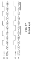
- FIG. 17 is a timing diagram which explains how the known video decoding device plays a 3:2 pulldown video, where the topmost two parts (A) and (B) show the result of forward playback.
- the fifth field is a copy of the third field "B1t”
- the tenth field is a copy of the eight field "P3b.” In this way, some field images in the original motion picture are repeatedly used in the playback sequence just to increase the frame rate so as to adhere to the existing television standards.
- Part (B) of FIG. 17 also demonstrates that the video decoding device maintains the normal field order of top, bottom, top, bottom, and so on, even if it has to insert extra fields to achieve the telecine conversion. In this way, the known video decoding device can smoothly play back 3:2 pulldown videos.
- the video decoding device When playing a 3:2 pulldown video backward, the video decoding device reads and outputs the pictures P3, I2, B1, B0 in that order, as in the case of ordinary videos.
- the aforementioned parameter "top_field_first” is set to "1" (i.e., read the top field first in forward playback mode)
- the known video decoding device interprets it reversely, thus outputting the bottom field first and then the top field.
- the bottommost two parts (C) and (D) of FIG. 17 show the field sequence in the present example. As seen, the first field is P3t, and the second is P3b. The third field is a copy of "P3t.” This is followed by I2t, I2b, B1b, and then B1t. The next field is a copy of B1b. Finally, the sequence ends with B0b and B0t.
- a forward-playback picture sequence (B) and a reverse-playback picture sequence (D) which are produced from the same set of 3:2 pulldown video and display parameters. It should be pointed out that the reverse-playback picture sequence (D) has some inconsistency in terms of the arrangement of neighboring fields.
- top fields be sent out when the v-sync signal is low, while bottom fields be sent out when the v-sync signal is high.
- a top field I2t comes in the fourth slot which is assigned to a bottom field.
- the fifth slot is occupied by the bottom field I2b although that slot is for a top field. Similar violation occurs in the ninth and tenth slots, too.
- the known method fails to maintain the consistent timing relationships between bottom fields and top fields.
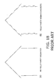
- This inability causes an artifact called "jaggies" illustrated in FIG. 18.
- the left part (A) of FIG. 18 shows an original picture encoded in a video stream.
- the known video decoding device would reproduce it as shown in the right part (B) of FIG. 18 when playing the video stream backward. Viewers might perceive such jaggies as an irritating flicker of images.
- embodiments of the present invention aim to provide a video decoding device with a reverse playback function which does not produce jaggies.
- a video decoding device which decodes a video stream containing MPEG-compressed frames each consisting of first and second fields while inserting extra fields into the video stream in process a specified number of times.
- This video decoding device comprises the following elements: a video data storage unit, an attribute data storage unit, and a reverse playback unit.
- the video data storage unit stores pictures constituting the video stream that is being played back.
- the attribute data storage unit stores attribute data describing how each picture should be displayed.
- the attribute data includes a repeat-first-field flag for each picture.
- the reverse playback unit determines whether the repeat-first-field flag in the attribute data storage unit is set or cleared, when playing back the video stream in a reverse direction.
- FIG. 1 is a conceptual view of a video decoding device according to the present invention.
- the proposed video decoding device 1 comprises a video data storage unit 1a, an attribute data storage unit 1b, and a reverse playback unit 1c.
- the video data storage unit 1a stores pictures constituting a video stream that is being played back.
- the attribute data storage unit 1b stores attribute data which describes how to display each picture. While FIG. 1 illustrates these two storage units 1a and 1b as separate elements, it is also possible to implement them as a unified block.
- repeat_first_field repeat-first-field
- FIG. 2 is a timing diagram which shows how the proposed device plays back a video bitstream containing pictures B0, B1, I2, and P3.
- the video data storage unit 1a in the proposed video decoding device 1 accepts a series of pictures B0, B1, I2, and P3, and stores them in separate memory areas.
- the attribute data storage unit 1b accepts attribute data of each picture and stores them in separate memory areas.
- the reverse playback unit 1c reads out pictures from the video data storage unit 1a according to their associated attribute data stored in the attribute data storage unit 1b.
- the attribute data includes such parameters that describe which of the top and bottom fields should be displayed first, and whether any extra field should be inserted. More specifically, suppose that the attribute data of pictures B0, B1 I2, and P3 provides the following playback conditions:
- the reverse playback unit 1c begins its task with reading out the last picture P3 from the video data storage unit 1a, in which the four pictures B0, B1, I2, and P3 are stored.
- the first field of P3 has to be repeated, and that first field should be the bottom field, as specified in the above playback conditions (3) and (2), respectively.
- the reverse playback unit 1c is designed to output the fields of a given picture in either way of the following:
- the reverse playback unit 1c now proceeds to the next picture I2.
- the attribute data of I2 requires that the bottom field be displayed first, and no field be repeated, as seen in the playback conditions (2) and (4), respectively. Since the processing rule (b) is applicable to I2, the reverse playback unit 1c reads and outputs the top field I2t first, and then the bottom field I2b.
- the reverse playback unit 1c proceeds to the next picture B1. Since the playback conditions (1) and (3) and processing rule (a) apply to the picture B1, the reverse playback unit 1c reads and outputs the top field B1t first, then the bottom field B1b, and the top field B1t again.
- the reverse playback unit 1c processes the next picture B0. Since the playback conditions (1) and (4) and processing rule (b) apply to the picture B0, the reverse playback unit 1c reads and outputs the bottom field B0b first and then the top field B1b.
- FIG. 3 is a block diagram of an embodiment of the present invention.
- the video decoding device of the present invention comprises a buffer memory 50, a video decoder 51, a decoding controller 52, a frame memory 53, a display controller 60, and a v-sync generator 55.
- the buffer memory 50 serves as a temporary storage space for buffering an incoming video bitstream.
- the video decoder 51 decodes video data stored in the buffer memory 50 in response to a decoding start command given from the decoding controller 52, and it stores the decoded I, P, and B pictures into the frame memory 53.
- the decoding controller 52 controls video decoding processes, including issuance of decoding start commands to the video decoder 51.
- the frame memory 53 has the capacity of four pictures (or four frames), the space of which is segmented into four sections to store individual pictures produced by the video decoder 51.
- the display controller 60 determines the direction of playback operation according to a playback direction flag which indicates whether it is forward playback or reverse playback.
- the display controller 60 also provides the frame memory 53 with display start commands in synchronization with a vertical synchronization (v-sync) signal. Further, the display controller 60 determines in what order to read pictures when displaying a video stream, consulting relevant display parameters stored in the frame memory 53.
- the display controller 60 operates differently from the known display controller 54 explained earlier in FIG. 15 because of the presence of a field order corrector 60a, while other elements are similar to those shown in FIG. 15. More specifically, the field order corrector 60a provides the functions of the reverse playback unit 1c explained in FIG. 1, correcting the order of output picture fields when playing back a given video stream in the reverse direction.
- the field order corrector 60a makes the display controller 60 change the interpretation of the "top_field_first" flag when "repeat_first_field” is "1,” so that the field parity will be maintained properly even in the reverse playback mode.
- the field order corrector 60a permits the display controller 60 to serve as the reverse playback unit 1c shown in FIG. 1.
- the next section explains more about the operation of the proposed embodiment including such a display controller 60, starting with a brief description of parameters used, and then proceeding to a more specific example of video decoding processes.
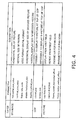
- FIG. 4 shows a set of parameters used in the present embodiment. As seen, the parameters include those for sequence layer, Group of Pictures (GOP) layer, and picture layer.
- GOP Group of Pictures
- sequence layer parameters include the following values:
- the GOP layer parameters include the following values:
- the picture layer paramters includes the following values:
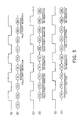
- FIG. 5 is a timing diagram which shows three possible picture sequences (B), (D), and (F), together with v-sync signals (A), (C), and (E) for timing reference.
- B picture sequences
- D digital to picture sequence
- F v-sync signals
- A v-sync signals
- C C
- E v-sync signals
- the first picture sequence (B) is an example of 3:2 pulldown video produced with a known method.
- the video decoding device can provide a jaggy-free 3:2 pulldown video.
- the video decoding device is receiving an MPEG bitstream of 3:2 pulldown video.
- the incoming bitstream is temporarily stored in the buffer memory 50 and then supplied to the video decoder 51.
- the decoding controller 52 issues decoding start commands, causing the video decoder 51 to reproduce motion pictures by decoding the bitstream sent from the buffer memory 50 in accordance with the syntax of MPEG video formats.
- the resultant pictures are supplied to the frame memory 53, and their display parameters are extracted and stored into appropriate storage areas associated with each picture bank of the frame memory 53.
- FIG. 6 shows an example of parameter settings in 3:2 pull-down video.
- the parameter values specified in this example are as follows.
- the first parameter “horizontal_size_value” in the table represents the horizontal picture size. This parameter is set to "704" for all pictures, as indicated by the left arrows " ⁇ " which are used as ditto symbols in FIG. 6.
- the next parameter “vertical_size_value” represents the vertical size, which is set to "480" for all pictures.
- the third parameter “frame_rate_code” specifies which frame rate to provide, NTSC or PAL. This parameter is set to "0100" for all pictures.
- the subsequent two parameters “display_horizontal_size” and “display_vertical_size” specify a display size, which are set to "704" and "480,” respectively, for all pictures.
- the sixth parameter "closed_gop” indicates that it is possible to decode and display B-pictures at the beginning of the current GOP, when it is set to "1."
- Pictures B0 and B1 have a value of "1" for this parameter, while I2 and P3 have no specified value.
- the seventh parameter “broken_link,” when it is set to "1,” indicates that it is not possible to decode and display B-pictures at the beginning of the current GOP.
- Pictures B0 and B1 have a value of "0" for this parameter, while I2 and P3 have no specified value.
- the seventh parameter “top_field_first” indicates that the first field of the current picture is to be displayed first, when it is set to “1.” This parameter is set to “1" for pictures B0 and B1, while it is “0” for the other pictures I2 and P3.
- the eighth parameter “repeat_first_field” indicates that the first field is to be repeated. This parameter is set to "1” for pictures B1 and P3 and "0” for pictures B0 and I2.
- the pan-scan parameters “frame_center_horizontal_offset” and “frame_center_vertical_offset, which specify the horizontal and vertical positions of a cropped picture, have no particular values in any of the four pictures in the present example.
- FIG. 7 shows an example of parameter settings in normal video.
- the normal video parameters are distinct in the setup of "top_field_first” and “repeat_first_field.” More specifically, “top_field_first” is set to “1” for all pictures, and “repeat_first_field” is set to "0" for all pictures.
- the pictures decoded in the above processing will now be displayed as follows.
- the display controller 60 detects every falling edge of the v-sync signal supplied from the v-sync generator 55, and then it reads display parameters out of one of the parameter banks corresponding to the next picture to be displayed. Since the four pictures are arranged in the order of B0, B1 I2, and P3, assuming forward playback, the display controller 60 starts its task with fetching the parameters of the last picture P3.
- the display controller 60 determines how to display the picture P3 of interest, according to the parameters read out of the relevant bank. Since the parameters of P3 are defined as shown in FIG. 6, the display controller 60 identifies that the picture P3 is 704 ⁇ 480 pixels in size, and that its top field should be displayed first.
- the display controller 60 retrieves picture data from the frame memory 53 for display.
- the display controller 60 reads out the data of picture P3 from the bank #3 since it has just finished the parameters of picture P3.
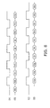
- FIG. 8 shows a forward-playback picture sequence (B) produced with a known method and a reverse-playback picture sequence (D) produced through the above-described process of the present embodiment. Both sequences (B) and (D) are depicted together with v-sync signals (A) and (C) for the purpose of timing reference.
- the present embodiment ensures that the top fields and bottom fields be aligned alternately throughout the sequence. It should be noted that every bottom field appears when the v-sync signal is high, and every top field appears when the v-sync signal is low. That is, the present embodiment maintains correct and consistent field parity which is required in interlaced video, and thus enables smooth reverse playback of 2:3 pulldown motion pictures.
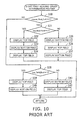
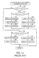
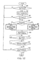
- FIGS. 9 to 11 are flowcharts of a known video display method, which comprises the following steps:
- FIGS. 9 to 11 The operation of the known video decoding devices have been described in FIGS. 9 to 11. Referring next to FIGS. 12 to 14, the playback operation of the proposed video decoding device will be described below.
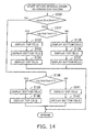
- the process of FIG. 12 comprises the following steps:
- FIGS. 12 to 14 has described the process flow of video playback according to the present embodiment.
- the present embodiment is different in steps S132 to 137 in FIG. 14. These steps read and display top and bottom fields in the opposite way to their counterparts in the known process shown in FIG. 11.
- the steps S132 to 137 execute the distinct tasks corresponding to the processing rule (a) described earlier, while the other steps are common to both methods. Because of this feature, the present embodiment enables a video decoding device to perform reverse playback without producing jaggies.
- the above-described processing mechanisms of the proposed video decoding device can be realized as software functions of a computer system, the instructions of which are encoded in the form of computer programs.
- the computer system executes such programs to provide the intended functions of the present invention.
- the programs are stored in computer-readable storage media including: magnetic storage media, optical discs, magneto-optical storage media, and solid state memory devices.
- Magnetic storage media include hard disk drives (HDD), flexible disks (FD), and magnetic tapes.
- Optical discs include digital versatile discs (DVD), DVD-RAM, compact disc read-only memory (CD-ROM), CD-Recordable (CD-R), and CD-Rewritable (CD-RW).
- Magneto-optical storage media include magneto-optical discs (MO).
- Portable storage media such as DVD and CD-ROM, are suitable for the circulation of computer programs.
- Network-based distribution of software programs is also possible, in which master program files stored in a server computer are downloaded to user computers via a network.
- Each user computer stores necessary programs in its local storage unit, which have previously been installed from a portable storage media or downloaded from a server computer.
- the user computer performs intended functions by executing the programs read out of the local storage unit.
- the user computer may execute the programs directly from the portable storage media.
- Another alternative method is that the user computer dynamically downloads programs from a server computer when they are demanded and executes them upon delivery.
- the proposed video decoding device decodes a video stream containing MPEG-compressed frames while converting frame rates by inserting extra fields.
- the device has a video data storage unit to store pictures being played back, and an attribute data storage unit to store attribute data which describes how each picture should be displayed. Each picture is interlaced into a first and second fields.
- the attribute data includes a repeat-first-field flag for each picture.
- a reverse playback unit determines whether the repeat-first-field flag is set or cleared, and plays back the first and second fields of each picture in the same order as that in forward playback mode if the repeat-first-field flag is set. If the repeat-first-field flag is cleared, it outputs the first and second fields in the opposite order to that in the forward playback mode.
- the video decoding device thus enables smooth, jaggy-free reverse playback of 3:2 pulldown video streams.
Landscapes
- Engineering & Computer Science (AREA)
- Multimedia (AREA)
- Signal Processing (AREA)
- Compression Or Coding Systems Of Tv Signals (AREA)
- Television Signal Processing For Recording (AREA)
- Television Systems (AREA)
Abstract
Description
display_horizontal_size_value=704
display_vertical_size_value=480
closed_gop=1
top_field_first=1
Those parameters tells the
- horizontal_size_value
- vertical_size_value
- frame_rate_code
- display_horizontal_size
- display_vertical_size
- closed_gop
- broken_link
- top_field_first
- repeat_first_field
- frame_center_horizontal_offset
- frame_center_vertical_offset
Claims (11)
- A video decoding device which decodes a video stream containing MPEG-compressed frames each consisting of first and second fields while inserting extra fields into the video stream in process a specified number of times, comprising:a video data storage unit (1a) which stores pictures constituting the video stream that is being played back;an attribute data storage unit (1b) which stores attribute data describing how each picture should be displayed, the attribute data including a repeat-first-field flag for each picture; anda reverse playback unit (1c) which determines whether the repeat-first-field flag in said attribute data storage unit is set or cleared when playing back the video stream in a reverse direction, and reads out the first and second fields of each picture in the same order as that in forward playback mode if the repeat-first-field flag is set, and in the opposite order to that in the forward playback mode if the repeat-first-field flag is cleared.
- The video decoding device according to claim 1, wherein said video data storage unit (1a) and said attribute data storage unit (1b) are implemented on a single semiconductor device.
- The video decoding device according to claim 1 or 2, wherein:the first field is a top field; andthe second field is a bottom field.
- The video decoding device according to any of claims 1, 2 or 3, wherein said reverse playback unit (1c) outputs a 3:2 pulldown video.
- The video decoding device according to any of claims 1 to 4, wherein the attribute data includes parameters specifying how each picture should be displayed.
- A method of decoding a video stream containing MPEG-compressed frames each consisting of first and second fields while inserting extra fields into the video stream in process a specified number of times, comprising the steps of:(a) storing pictures that constitute the video stream being played back;(b) storing attribute data that describes how each picture should be displayed, the attribute data including a repeat-first-field flag for each picture; and(c) determining whether the repeat-first-field flag stored in said attribute data storing step (b) is set or cleared when playing back the video stream in a reverse direction, and reading out the first and second fields of each picture in the same order as that in forward playback mode if the repeat-first-field flag is set, and in the opposite order to that in the forward playback mode if the repeat-first-field flag is cleared.
- A program product which enables a computer to decode a video stream containing MPEG-compressed frames each consisting of first and second fields while inserting extra fields into the video stream in process a specified number of times, the program product causing the computer to function as:a video data storage unit (1a) which stores pictures constituting the video stream that is being played back;an attribute data storage unit (1b) which stores attribute data describing how each picture should be displayed, the attribute data including a repeat-first-field flag for each picture; anda reverse playback unit (1c) which determines whether the repeat-first-field flag in said attribute data storage unit is set or cleared when playing back the video stream in a reverse direction, and reads out the first and second fields of each picture in the same order as that in forward playback mode if the repeat-first-field flag is set, and in the opposite order to that in the forward playback mode if the repeat-first-field flag is cleared.
- The program product according to claim 7, wherein said video data storage unit (1a) and attribute data storage unit (1b) are implemented on a single semiconductor device.
- The program product according to claim 7 or 8, wherein:the first field is a top field; andthe second field is a bottom field.
- The program product according to any of claims 7, 8 or 9, wherein said reverse playback unit (1c) outputs a 3:2 pulldown video.
- The program product according to any of claims 7 to 10, wherein the attribute data includes parameters specifying how each picture should be displayed.
Applications Claiming Priority (2)
| Application Number | Priority Date | Filing Date | Title |
|---|---|---|---|
| JP2001185793A JP4458714B2 (en) | 2001-06-20 | 2001-06-20 | Image decoding apparatus, image decoding method, and program |
| JP2001185793 | 2001-06-20 |
Publications (2)
| Publication Number | Publication Date |
|---|---|
| EP1271959A2 true EP1271959A2 (en) | 2003-01-02 |
| EP1271959A3 EP1271959A3 (en) | 2005-01-26 |
Family
ID=19025315
Family Applications (1)
| Application Number | Title | Priority Date | Filing Date |
|---|---|---|---|
| EP20020252700 Ceased EP1271959A3 (en) | 2001-06-20 | 2002-04-16 | Video decoding device and method, and program product therefor |
Country Status (3)
| Country | Link |
|---|---|
| US (1) | US7460599B2 (en) |
| EP (1) | EP1271959A3 (en) |
| JP (1) | JP4458714B2 (en) |
Cited By (2)
| Publication number | Priority date | Publication date | Assignee | Title |
|---|---|---|---|---|
| US7526179B2 (en) | 2003-04-10 | 2009-04-28 | Panasonic Corporation | Information recording medium, and apparatus and method for recording information to information recording medium |
| EP2109312A1 (en) * | 2008-04-11 | 2009-10-14 | Tektronix International Sales GmbH | A method of identifying inconsistent field dominance metadata in a sequence of video frames |
Families Citing this family (22)
| Publication number | Priority date | Publication date | Assignee | Title |
|---|---|---|---|---|
| US20040258160A1 (en) * | 2003-06-20 | 2004-12-23 | Sandeep Bhatia | System, method, and apparatus for decoupling video decoder and display engine |
| US7724827B2 (en) * | 2003-09-07 | 2010-05-25 | Microsoft Corporation | Multi-layer run level encoding and decoding |
| US7961786B2 (en) * | 2003-09-07 | 2011-06-14 | Microsoft Corporation | Signaling field type information |
| US8107531B2 (en) | 2003-09-07 | 2012-01-31 | Microsoft Corporation | Signaling and repeat padding for skip frames |
| US8064520B2 (en) | 2003-09-07 | 2011-11-22 | Microsoft Corporation | Advanced bi-directional predictive coding of interlaced video |
| US8077778B2 (en) * | 2003-10-31 | 2011-12-13 | Broadcom Corporation | Video display and decode utilizing off-chip processor and DRAM |
| US7675872B2 (en) | 2004-11-30 | 2010-03-09 | Broadcom Corporation | System, method, and apparatus for displaying pictures |
| US7885338B1 (en) * | 2005-04-25 | 2011-02-08 | Apple Inc. | Decoding interdependent frames of a video for display |
| US20080034388A1 (en) * | 2006-08-03 | 2008-02-07 | Sina Majidi | System of mobile and stationary digital units using a logical network architecture involving groups and hierarchies |
| US8134640B2 (en) * | 2006-12-26 | 2012-03-13 | Broadcom Corporation | Video processor architecture and method for frame rate conversion |
| US8285068B2 (en) * | 2008-06-25 | 2012-10-09 | Cisco Technology, Inc. | Combined deblocking and denoising filter |
| US20100177161A1 (en) * | 2009-01-15 | 2010-07-15 | Dell Products L.P. | Multiplexed stereoscopic video transmission |
| US8520731B2 (en) * | 2009-06-05 | 2013-08-27 | Cisco Technology, Inc. | Motion estimation for noisy frames based on block matching of filtered blocks |
| US8619881B2 (en) * | 2009-06-05 | 2013-12-31 | Cisco Technology, Inc. | Estimation of temporal depth of 3D overlapped transforms in video denoising |
| US8615044B2 (en) | 2009-06-05 | 2013-12-24 | Cisco Technology, Inc. | Adaptive thresholding of 3D transform coefficients for video denoising |
| US8358380B2 (en) * | 2009-06-05 | 2013-01-22 | Cisco Technology, Inc. | Efficient spatial and temporal transform-based video preprocessing |
| US8571117B2 (en) * | 2009-06-05 | 2013-10-29 | Cisco Technology, Inc. | Out of loop frame matching in 3D-based video denoising |
| US8638395B2 (en) | 2009-06-05 | 2014-01-28 | Cisco Technology, Inc. | Consolidating prior temporally-matched frames in 3D-based video denoising |
| US8472725B2 (en) | 2010-06-02 | 2013-06-25 | Cisco Technology, Inc. | Scene change detection and handling for preprocessing video with overlapped 3D transforms |
| US9635308B2 (en) | 2010-06-02 | 2017-04-25 | Cisco Technology, Inc. | Preprocessing of interlaced video with overlapped 3D transforms |
| US9628674B2 (en) | 2010-06-02 | 2017-04-18 | Cisco Technology, Inc. | Staggered motion compensation for preprocessing video with overlapped 3D transforms |
| US9832351B1 (en) | 2016-09-09 | 2017-11-28 | Cisco Technology, Inc. | Reduced complexity video filtering using stepped overlapped transforms |
Family Cites Families (13)
| Publication number | Priority date | Publication date | Assignee | Title |
|---|---|---|---|---|
| ES2082134T3 (en) * | 1990-03-30 | 1996-03-16 | Accom | FIXED IMAGE STORAGE SYSTEM AND METHOD AND METHOD WITH ACCESS TO A SIMPLE IMAGE. |
| US5243422A (en) * | 1990-11-13 | 1993-09-07 | Hitachi, Ltd. | Field converting method for television signals and device for realizing same |
| US5497237A (en) * | 1991-10-29 | 1996-03-05 | Hitachi, Ltd. | Method of converting a field of a regenerative signal a VTR and apparatus employing the same |
| US5907660A (en) * | 1994-09-21 | 1999-05-25 | Mitsubishi Denki Kabushiki Kaisha | Digital video signal playback device with special playback data being in the form of a still image slice data |
| US5592299A (en) * | 1994-09-26 | 1997-01-07 | Hitachi America, Ltd. | Method and apparatus for reducing the amount of data required to represent a video frame |
| US5793927A (en) * | 1995-06-07 | 1998-08-11 | Hitachi America, Ltd. | Methods for monitoring and modifying a trick play data stream to insure MPEG compliance |
| US6118491A (en) | 1997-02-20 | 2000-09-12 | Lsi Logic Corporation | System and method for enforcing interlaced field synchronization in the presence of broken alternation in an MPEG video datastream |
| KR100574186B1 (en) | 1997-10-03 | 2006-04-27 | 소니 가부시끼 가이샤 | Coded stream splicing device and method, Coded stream generating device and method and editing device, method and editing system |
| JP4121590B2 (en) * | 1997-10-30 | 2008-07-23 | 株式会社ルネサステクノロジ | Image display device and special reproduction control device thereof |
| US6487642B1 (en) * | 1998-10-22 | 2002-11-26 | Sony Corporation | Command manager |
| EP1032203A3 (en) | 1999-02-26 | 2002-11-06 | Sony Corporation | Data transmitting apparatus and method thereof, recording apparatus, and recording and reproducing apparatus |
| US6658056B1 (en) | 1999-03-30 | 2003-12-02 | Sony Corporation | Digital video decoding, buffering and frame-rate converting method and apparatus |
| US6791622B2 (en) * | 2001-08-31 | 2004-09-14 | General Instrument Corporation | Methods and apparatus for providing video still frame and video capture features from interlaced video signals |
-
2001
- 2001-06-20 JP JP2001185793A patent/JP4458714B2/en not_active Expired - Fee Related
-
2002
- 2002-03-26 US US10/105,215 patent/US7460599B2/en not_active Expired - Fee Related
- 2002-04-16 EP EP20020252700 patent/EP1271959A3/en not_active Ceased
Cited By (8)
| Publication number | Priority date | Publication date | Assignee | Title |
|---|---|---|---|---|
| US7526179B2 (en) | 2003-04-10 | 2009-04-28 | Panasonic Corporation | Information recording medium, and apparatus and method for recording information to information recording medium |
| US8094994B2 (en) | 2003-04-10 | 2012-01-10 | Panasonic Corporation | Information recording medium, and apparatus and method for recording information to information recording medium |
| US8103152B2 (en) | 2003-04-10 | 2012-01-24 | Panasonic Corporation | Information recording medium, and apparatus and method for recording information to information recording medium |
| US8160432B2 (en) | 2003-04-10 | 2012-04-17 | Panasonic Corporation | Information recording medium, and apparatus and method for recording information to information recording medium |
| US8224162B2 (en) | 2003-04-10 | 2012-07-17 | Panasonic Corporation | Information recording medium, and apparatus and method for recording information to information recording medium |
| US8290347B2 (en) | 2003-04-10 | 2012-10-16 | Panasonic Corporation | Information recording medium, and apparatus and method for recording information to information recording medium |
| EP2109312A1 (en) * | 2008-04-11 | 2009-10-14 | Tektronix International Sales GmbH | A method of identifying inconsistent field dominance metadata in a sequence of video frames |
| CN101692709B (en) * | 2008-04-11 | 2013-05-22 | 特克特朗尼克国际销售有限责任公司 | A method of identifying inconsistent field dominance metadata in a sequence of video frames |
Also Published As
| Publication number | Publication date |
|---|---|
| JP4458714B2 (en) | 2010-04-28 |
| JP2003009083A (en) | 2003-01-10 |
| EP1271959A3 (en) | 2005-01-26 |
| US20020196857A1 (en) | 2002-12-26 |
| US7460599B2 (en) | 2008-12-02 |
Similar Documents
| Publication | Publication Date | Title |
|---|---|---|
| US20020196857A1 (en) | Video decoding device and method, and program product therefor | |
| US5508750A (en) | Encoding data converted from film format for progressive display | |
| US20030053540A1 (en) | Generation of MPEG slow motion playout | |
| US6525774B1 (en) | Inverse telecine converting device and inverse telecine converting method | |
| JPH10145779A (en) | Field detection device and field detection method, image encoding device and image encoding method, and recording medium and recording method | |
| US20050117654A1 (en) | High-definition dual video decoder and decoding method, and digital broadcasting receiver using the same | |
| US20020167607A1 (en) | Method and device for generating a video signal | |
| KR100246762B1 (en) | Video data decoding method | |
| US7596297B2 (en) | Information processing apparatus and method program, and recording medium | |
| JP3551887B2 (en) | Moving image reproducing method and apparatus | |
| US8269887B2 (en) | Image processing method, image processing program and image processing apparatus, and playback method, playback program and playback apparatus | |
| US20040264578A1 (en) | Method and/or apparatus for decoding an intra-only MPEG-2 stream composed of two separate fields encoded as a special frame picture | |
| US20040190628A1 (en) | Video information decoding apparatus and method | |
| JP2008167061A (en) | Encoding apparatus and encoding method | |
| JP4906197B2 (en) | Decoding device and method, and recording medium | |
| JP3570785B2 (en) | Moving image expansion / reproduction method and apparatus | |
| US7843489B2 (en) | Maintaining continuous film mode with bad edits | |
| JP4769268B2 (en) | MPEG video decoder and MPEG video decoding method | |
| JPH1168881A (en) | Data stream processing apparatus and method | |
| JP4935661B2 (en) | Playback apparatus, playback method, and playback program | |
| JPH1093969A (en) | Video encoding device | |
| US6400895B1 (en) | Method for optimizing MPEG-2 video playback consistency | |
| US20060274200A1 (en) | Decoder and method for decoding bit stream | |
| US8681269B2 (en) | Video reproduction apparatus and video reproducing method | |
| JP3671969B2 (en) | Data multiplexing method and multiple data decoding method |
Legal Events
| Date | Code | Title | Description |
|---|---|---|---|
| PUAI | Public reference made under article 153(3) epc to a published international application that has entered the european phase |
Free format text: ORIGINAL CODE: 0009012 |
|
| AK | Designated contracting states |
Kind code of ref document: A2 Designated state(s): AT BE CH CY DE DK ES FI FR GB GR IE IT LI LU MC NL PT SE TR |
|
| AX | Request for extension of the european patent |
Free format text: AL;LT;LV;MK;RO;SI |
|
| PUAL | Search report despatched |
Free format text: ORIGINAL CODE: 0009013 |
|
| AK | Designated contracting states |
Kind code of ref document: A3 Designated state(s): AT BE CH CY DE DK ES FI FR GB GR IE IT LI LU MC NL PT SE TR |
|
| AX | Request for extension of the european patent |
Extension state: AL LT LV MK RO SI |
|
| RIC1 | Information provided on ipc code assigned before grant |
Ipc: 7H 04N 7/50 A |
|
| 17P | Request for examination filed |
Effective date: 20050523 |
|
| AKX | Designation fees paid |
Designated state(s): DE FR GB |
|
| RAP1 | Party data changed (applicant data changed or rights of an application transferred) |
Owner name: FUJITSU MICROELECTRONICS LIMITED |
|
| RAP1 | Party data changed (applicant data changed or rights of an application transferred) |
Owner name: FUJITSU SEMICONDUCTOR LIMITED |
|
| STAA | Information on the status of an ep patent application or granted ep patent |
Free format text: STATUS: THE APPLICATION HAS BEEN REFUSED |
|
| 18R | Application refused |
Effective date: 20101118 |