EP1271874A1 - Multilevel modulating method, multilevel demodulating method, and multilevel modulating/demodulating method - Google Patents
Multilevel modulating method, multilevel demodulating method, and multilevel modulating/demodulating method Download PDFInfo
- Publication number
- EP1271874A1 EP1271874A1 EP01930214A EP01930214A EP1271874A1 EP 1271874 A1 EP1271874 A1 EP 1271874A1 EP 01930214 A EP01930214 A EP 01930214A EP 01930214 A EP01930214 A EP 01930214A EP 1271874 A1 EP1271874 A1 EP 1271874A1
- Authority
- EP
- European Patent Office
- Prior art keywords
- bit
- data
- bits
- dummy
- symbol
- Prior art date
- Legal status (The legal status is an assumption and is not a legal conclusion. Google has not performed a legal analysis and makes no representation as to the accuracy of the status listed.)
- Granted
Links
Images














Classifications
-
- H—ELECTRICITY
- H04—ELECTRIC COMMUNICATION TECHNIQUE
- H04L—TRANSMISSION OF DIGITAL INFORMATION, e.g. TELEGRAPHIC COMMUNICATION
- H04L27/00—Modulated-carrier systems
- H04L27/32—Carrier systems characterised by combinations of two or more of the types covered by groups H04L27/02, H04L27/10, H04L27/18 or H04L27/26
- H04L27/34—Amplitude- and phase-modulated carrier systems, e.g. quadrature-amplitude modulated carrier systems
- H04L27/36—Modulator circuits; Transmitter circuits
-
- H—ELECTRICITY
- H04—ELECTRIC COMMUNICATION TECHNIQUE
- H04L—TRANSMISSION OF DIGITAL INFORMATION, e.g. TELEGRAPHIC COMMUNICATION
- H04L27/00—Modulated-carrier systems
- H04L27/32—Carrier systems characterised by combinations of two or more of the types covered by groups H04L27/02, H04L27/10, H04L27/18 or H04L27/26
- H04L27/34—Amplitude- and phase-modulated carrier systems, e.g. quadrature-amplitude modulated carrier systems
- H04L27/3405—Modifications of the signal space to increase the efficiency of transmission, e.g. reduction of the bit error rate, bandwidth, or average power
- H04L27/3411—Modifications of the signal space to increase the efficiency of transmission, e.g. reduction of the bit error rate, bandwidth, or average power reducing the peak to average power ratio or the mean power of the constellation; Arrangements for increasing the shape gain of a signal set
-
- H—ELECTRICITY
- H04—ELECTRIC COMMUNICATION TECHNIQUE
- H04L—TRANSMISSION OF DIGITAL INFORMATION, e.g. TELEGRAPHIC COMMUNICATION
- H04L7/00—Arrangements for synchronising receiver with transmitter
- H04L7/04—Speed or phase control by synchronisation signals
- H04L7/041—Speed or phase control by synchronisation signals using special codes as synchronising signal
- H04L2007/045—Fill bit or bits, idle words
Definitions
- the present invention relates to a multi-level modulation method, multi-level demodulation method and multi-level modulation and demodulation method for modulating or demodulating data consisting of a plurality of symbols.
- a conventional multi-level modulation method transmits data consisting of a plurality of symbols by passing the data through multi-level modulation (Fig. 1 shows an example in which each symbol undergoes 4-bit 16 QAM).
- Fig. 1 shows an example in which each symbol undergoes 4-bit 16 QAM.
- the data cannot undergo the multi-level modulation.
- the data is provided with additional dummy bits to be interleaved.
- the transmission power of each symbol after interleaving can either increase or decrease.
- the conventional multi-level modulation method has the following problem:
- the transmission power of the symbol constituting the data is not always small, and the increase in the transmission power of the symbol causes a problem of increasing the interference to other signals.
- an object of the present invention is to provide a multi-level modulation method and multi-level modulation and demodulation method capable of reducing the transmission power of the symbol and the interference to other signals.
- Another object of the present invention is to provide a multi-level demodulation method and multi-level modulation and demodulation method capable of receiving data with small interference to other signals and of demodulating the data.
- a multi-level modulation and demodulation method including the steps of: mapping, when a number of bits of data consisting of a plurality of symbols is less than a number of bits of a radio frame, abit stream of the data such that a specified bit of at least one symbol becomes a dummy bit; transmitting the data after mapping by passing the data through multi-level modulation; and performing, when receiving the data, the multi-level demodulation of the data considering that at least one specified bit of the symbol is a dummy bit.
- a dummy bit of "0" may be assigned to the lowest two bits of the symbol.
- transmission power may be turned off.
- a dummy bit of "0" may be assigned to intermediate two bits of the symbol.
- a dummy bit of "0" may be assigned to intermediate two bits of the symbol and a dummy bit of "1" may be assigned to the lowest two bits of the symbol.
- a dummy bit of "0" may be assigned to all the bits of the symbol.
- the dummy bits When the dummy bits are added to the data in the multi-level modulation and demodulation method in accordance with the present invention, the dummy bits may be distributed to a plurality of symbols.
- two dummy bits may be assigned to each of the symbols, and when the dummy bits are left even after assigning the two dummy bits to each of all the symbols, another two bits maybe assigned to some of the symbols.
- the dummy bits may be mapped in such a manner that their allocation positions in individual codes do not overlap with each other.
- one of dummy bits of "0" and “1" may be selected and disposed such that a signal constellation of the symbol is placed at an inmost possible region.
- one of the dummy bits of "0" and “1" may be selected with reference to a table that defines a bit value of each dummy bit that will place the signal constellation of the symbol at the inmost possible region.
- Fig. 3 is a block diagram showing a configuration of a multi-level modulation and demodulation system to which a multi-level modulation and demodulation method of an embodiment 1 in accordance with the present invention is applied.
- the reference numeral 1 designates a multi-level modulator for carrying out multi-level modulation of data consisting of a plurality of symbols to be transmitted
- 2 designates a multi-level demodulator for receiving the data consisting of a plurality of symbols and carrying out multi-level demodulation.
- the reference numeral 11 designates a transmission data generator for generating the data consisting of a plurality of symbols; 12 designates a channel encoder for mapping the bit stream of the data in such a manner that a specified bit of at least one symbol becomes a dummy bit, when the number of bits of the data generated by the data transmission data generator 11 is less than that of the radio frame; 13 designates a modulation stage for carrying out multi-level modulation of the data output from the channel encoder 12; 14 designates an RF stage for causing an antenna 15 to make radio transmission of the data passing through the multi-level modulation by the modulation stage 13; and 15 designates the antenna.
- Fig. 4 is a flowchart illustrating the multi-level modulation method of the embodiment 1 in accordance with the present invention
- Fig. 5 is a flowchart illustrating the multi-level demodulation method of the embodiment 1 in accordance with the present invention.
- the transmission data generator 11 of the multi-level modulator 1 generates the data consisting of a plurality of symbols as illustrated in Fig. 6 (step ST1). For convenience of explanation, it is assumed that each symbol generates 4-bit data, and undergoes 16-QAM multi-level modulation.
- the channel encoder 12 When the number of bits of the data generated by the transmission data generator 11 is less than that of the radio frame, the channel encoder 12 cannot perform the multi-level modulation of the data. Accordingly, it maps the bit stream of the data such that a specified bit of at least one symbol becomes a dummy bit (steps ST2 and ST3).
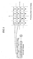
- the channel encoder 12 maps the bit stream of the data such that the lowest two bits of the symbols are assigned dummy bits of "0".
- the signal points of the symbols with their lowest two bits being "0" are allocated at shaded regions adjacent to the origin of an IQ coordinate system, at which the power amplitude is zero. Therefore, the transmission power of the symbols is small.
- the modulation stage 13 carries out the multi-level modulation of the data after mapping (step ST4).
- the RF stage 14 conducts the radio transmission of the data passing through the multi-level modulation by the modulation stage 13 using the antenna 15 (step ST5).
- the RF stage 17 of the multi-level demodulator 2 receives the data transmitted by the multi-level modulator 1 (step ST11).
- the demodulation stage 18 carries out the multi-level demodulation of the data received by the RF stage 17 (step ST12).
- the channel decoder 19 removes the dummy bits from the data passing through the multi-level demodulation by the demodulation stage 18 (step ST13). Specifically, the channel decoder 19, receiving information about the symbols and bit positions of the dummy bits from the multi-level modulator 1, recognizes the insertion position of the dummy bits, and eliminates the dummy bits from the data. As described above, the embodiment 1 maps the bit stream of the data in such a manner that a specified bit or bits of at least one symbol become dummy bits. As a result, it offers an advantage of being able to reduce the transmission power of the symbol, thereby suppressing the interference to other signals.
- the transmission power can be turned off at the positions.
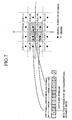
- the present embodiment 2 conducts 6-bit 64 QAM of each symbol as shown in Fig. 8, in which case, two bits at the middle of the symbol are assigned the dummy bits of "0".
- the signal points of the symbols with their middle two bits being "0" are allocated at shaded regions close to the origin of the IQ coordinate system.
- dummy bits of "1" are assigned to the lowest two bits of the symbol in addition to the dummy bits of "0" assigned to the two bits at the middle of the symbol.
- the signal points of the symbols are assigned to the boldly hatched region adjacent to the origin of the IQ coordinate system.
- the foregoing embodiments 1 and 2 allocate the dummy bits to the predetermined bits of the symbol, this is not essential.
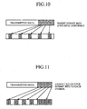
- the dummy bits are distributed among a plurality of symbols as shown in Fig. 10, thereby mapping the dummy bits as uniform as possible.
- the present embodiment 3 offers an advantage of being able to prevent errors because of the effect of fading.
- Fig. 11 shows another distribution, in which each symbol is assigned two dummy bits. If some dummy bits remain unassigned after completing the assignment of the dummy bits to all the symbols, they are assigned to some symbols four bits per symbol (in the example Fig. 11, the 4-bit allocation of the dummy bits is made to the right-hand symbols).
- the present embodiment 4 offers an advantage of being able to prevent the error because of the effect of fading, and to reduce the transmission power of the data as a whole.
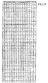
- the embodiments 1-4 do not mention, when the multi-level modulator 1 transmits data in multi-code as shown in Fig. 12, the dummy bits of the individual codes are mapped such that their positions do not overlap with each other.
- the present embodiment 5 offers an advantage of being able to prevent the error because of the effect of fading.
- the foregoing embodiment 1 handles the case that places the dummy bits of "0" at the lowest two bits of the symbols, the dummy bits can be disposed in other positions as follows.
- the dummy bit is replaced by "0" or "1" so that the signal constellation of the symbol is placed at the inmost possible regions.
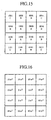
- Fig. 15 is a diagram showing a 16-QAM signal constellation
- Fig. 16 is a diagram showing the power of the phase points.
- the power at the phase points A in Fig. 15 is least, the power at the phase points B is second, and the power at the phase points C is greatest. Therefore, the table is formed such that the phase points of the bit arrangement after the replacement become the phase points A whenever possible. The table is formed such that when the phase points A cannot be assigned, the phase points B are assigned, and when the phase points B cannot be assigned, the phase points C are assigned.
- each symbol consists of four bits ⁇ b0, b1, b2, b3 ⁇
- this is not essential.
- the technique is also applicable to the 64-QAM where each symbol consists of six bits ⁇ b0, b1, b2, b3, b4, b5 ⁇ .
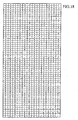
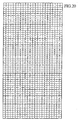
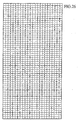
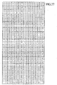
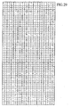
- 3 6 729 ways of bit combinations will occur at the same probability when the occurrence probabilities of "0", “1” and “DTX (dummy bits)" are equal.
- a symbol includes at least one dummy bit in the six bits ⁇ b0, b1, b2, b3, b4, b5 ⁇
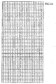
- Fig. 31 is a diagram showing a 64-QAM signal constellation
- Fig. 32 is a diagram showing the power of the phase points.
- the table is formed such that the phase points of the bit arrangement after the replacement become the phase points A or B whenever possible.
- the multi-level modulation and demodulation method in accordance with the present invention is suitable for the system required to reduce the transmission power of the data, and the interference to other signals.
Landscapes
- Engineering & Computer Science (AREA)
- Computer Networks & Wireless Communication (AREA)
- Signal Processing (AREA)
- Digital Transmission Methods That Use Modulated Carrier Waves (AREA)
Abstract
Description
Claims (13)
- A multi-level modulation method of performing, when transmitting data consisting of a plurality of symbols after multi-level modulation of the data, the multi-level modulation of the data by adding a dummy bit to the data when a number of bits of the data is less than a number of bits of a radio frame, the multi-level modulation method comprising the step of mapping a bit stream of the data such that a specified bit of at least one symbol becomes a dummy bit.
- A multi-level demodulation method of performing multi-level demodulation of data consisting of a plurality of symbols by receiving the data, the multi-level demodulation method comprising the step of performing the multi-level demodulation of the data considering that a specified bit of at least one symbol is a dummy bit.
- A multi-level modulation and demodulation method comprising the steps of: mapping, when a number of bits of data consisting of a plurality of symbols is less than a number of bits of a radio frame, a bit stream of the data such that a specified bit of at least one symbol becomes a dummy bit; transmitting the data after mapping by passing the data through multi-level modulation; and performing, when receiving the data, the multi-level demodulation of the data considering that at least one specified bit of the symbol is a dummy bit.
- The multi-level modulation and demodulation method according to claim 3, wherein when the symbol undergoes 4-bit 16 QAM, a dummy bit of "0" is assigned to the lowest two bits of the symbol.
- The multi-level modulation and demodulation method according to claim 3, wherein when the symbol undergoes 4-bit 16 QAM, transmission power is turned off.
- The multi-level modulation and demodulation method according to claim 3, wherein when the symbol undergoes 6-bit 64 QAM, a dummy bit of "0" is assigned to intermediate two bits of the symbol.
- The multi-level modulation and demodulation method according to claim 3, wherein when the symbol undergoes 6-bit 64 QAM, a dummy bit of "0" is assigned to intermediate two bits of the symbol and a dummy bit of "1" is assigned to lowest two bits of the symbol.
- The multi-level modulation and demodulation method according to claim 3, wherein when the symbol undergoes 6-bit 64 QAM, transmission power is turned off.
- The multi-level modulation and demodulation method according to claim 3, wherein when the dummy bits are added to the data, the dummy bits are distributed to a plurality of symbols.
- The multi-level modulation and demodulation method according to claim 3, wherein two dummy bits are assigned to each of the symbols, and when the dummy bits are left even after assigning the two dummy bits to each of all the symbols, another two bits are assigned to some of the symbols.
- The multi-level modulation and demodulation method according to claim 3, wherein when carrying out multi-code transmission of the data, the dummy bits are mapped such that their allocation positions in individual codes do not overlap with each other.
- The multi-level modulation and demodulation method according to claim 3, wherein when adding each dummy bit to the data, one of dummy bits of "0" and "1" is selected and disposed such that a signal constellation of the symbol is placed at an inmost possible region.
- The multi-level modulation and demodulation method according to claim 12, wherein one of the dummy bits of "0" and "1" is selected with reference to a table that defines a bit value of each dummy bit that will place the signal constellation of the symbol at the inmost possible region.
Applications Claiming Priority (3)
| Application Number | Priority Date | Filing Date | Title |
|---|---|---|---|
| PCT/JP2001/000983 WO2002065724A1 (en) | 2001-02-13 | 2001-02-13 | Multiple-level modulating method, multiple-level demodulating method, and multiple-level modulating/demodulating method |
| WOPCT/JP01/00983 | 2001-02-13 | ||
| PCT/JP2001/004182 WO2002065723A1 (en) | 2001-02-13 | 2001-05-18 | Multilevel modulating method, multilevel demodulating method, and multilevel modulating/demodulating method |
Publications (3)
| Publication Number | Publication Date |
|---|---|
| EP1271874A1 true EP1271874A1 (en) | 2003-01-02 |
| EP1271874A4 EP1271874A4 (en) | 2006-01-18 |
| EP1271874B1 EP1271874B1 (en) | 2007-07-11 |
Family
ID=11737016
Family Applications (1)
| Application Number | Title | Priority Date | Filing Date |
|---|---|---|---|
| EP01930214A Expired - Lifetime EP1271874B1 (en) | 2001-02-13 | 2001-05-18 | Multilevel modulating method with insertion of dummy bits |
Country Status (6)
| Country | Link |
|---|---|
| US (1) | US20030112888A1 (en) |
| EP (1) | EP1271874B1 (en) |
| JP (1) | JPWO2002065723A1 (en) |
| CN (1) | CN1422479A (en) |
| DE (1) | DE60129306T2 (en) |
| WO (2) | WO2002065724A1 (en) |
Cited By (4)
| Publication number | Priority date | Publication date | Assignee | Title |
|---|---|---|---|---|
| EP1418694A3 (en) * | 2002-10-31 | 2006-11-08 | Lg Electronics Inc. | BIT processing method for adaptive multirate modulation |
| EP2130306A1 (en) * | 2007-03-26 | 2009-12-09 | Nokia Siemens Networks Gmbh & Co. Kg | Method and device for reducing transmission power of packet oriented data and communication system comprising such device |
| WO2010071546A1 (en) * | 2008-12-17 | 2010-06-24 | Telefonaktiebolaget L M Ericsson (Publ) | Handling discontinuous transmission indication bits |
| EP2180650A4 (en) * | 2007-08-13 | 2013-03-20 | China Academy Of Telecomm Tech | A method and device for modulating the information of tfci |
Families Citing this family (16)
| Publication number | Priority date | Publication date | Assignee | Title |
|---|---|---|---|---|
| US20070110074A1 (en) | 2004-06-04 | 2007-05-17 | Bob Bradley | System and Method for Synchronizing Media Presentation at Multiple Recipients |
| US8443038B2 (en) | 2004-06-04 | 2013-05-14 | Apple Inc. | Network media device |
| US8797926B2 (en) | 2004-06-04 | 2014-08-05 | Apple Inc. | Networked media station |
| US10972536B2 (en) | 2004-06-04 | 2021-04-06 | Apple Inc. | System and method for synchronizing media presentation at multiple recipients |
| PT2793439T (en) | 2005-08-05 | 2019-01-17 | Panasonic Corp | System for transmitting and receiving modulated data |
| IN2011KN02769A (en) * | 2009-02-09 | 2015-07-10 | Huawei Tech Co Ltd | |
| CN102208975B (en) * | 2011-04-07 | 2013-09-18 | 泉州天地星电子有限公司 | Signal encoding/encryption transmission method |
| EP2945291B1 (en) | 2013-01-11 | 2019-12-18 | Sun Patent Trust | Data processing method, precoding method, and communication device |
| JP5775105B2 (en) * | 2013-03-04 | 2015-09-09 | 日本電信電話株式会社 | Transmitting apparatus / method and receiving apparatus / method in a passive optical communication network |
| US10044405B2 (en) | 2015-11-06 | 2018-08-07 | Cable Television Laboratories, Inc | Signal power reduction systems and methods |
| CN121864105A (en) * | 2015-12-23 | 2026-04-14 | 三星电子株式会社 | Apparatus for processing low density parity check code and method thereof |
| US11297369B2 (en) | 2018-03-30 | 2022-04-05 | Apple Inc. | Remotely controlling playback devices |
| US10993274B2 (en) | 2018-03-30 | 2021-04-27 | Apple Inc. | Pairing devices by proxy |
| US10783929B2 (en) | 2018-03-30 | 2020-09-22 | Apple Inc. | Managing playback groups |
| US10614857B2 (en) | 2018-07-02 | 2020-04-07 | Apple Inc. | Calibrating media playback channels for synchronized presentation |
| WO2021199409A1 (en) * | 2020-04-02 | 2021-10-07 | 三菱電機株式会社 | Error-correction coding device, error-correction decoding device, control circuit, storage medium, error-correction coding method, and error-correction decoding method |
Family Cites Families (17)
| Publication number | Priority date | Publication date | Assignee | Title |
|---|---|---|---|---|
| JPS61281654A (en) * | 1985-05-29 | 1986-12-12 | Kenwood Corp | Modulating system for time division multiplexing signal |
| JPS62176243A (en) * | 1986-01-30 | 1987-08-03 | Nec Corp | Fsk modulator stabilizing method for tdma |
| JPH0611131B2 (en) * | 1986-12-19 | 1994-02-09 | 富士通株式会社 | Frame synchronization method |
| JPH02279033A (en) * | 1989-04-20 | 1990-11-15 | Nec Corp | Picture transmission method |
| EP0685132A1 (en) * | 1991-05-29 | 1995-12-06 | Communications Satellite Corporation | Fully meshed cdma network for personal communications terminals |
| US5239557A (en) * | 1992-04-10 | 1993-08-24 | Ericsson/Ge Mobile Communications | Discountinuous CDMA reception |
| JPH09252326A (en) * | 1996-03-15 | 1997-09-22 | Kokusai Electric Co Ltd | Digital wireless terminal device and battery monitoring control method thereof |
| JPH1013404A (en) * | 1996-06-25 | 1998-01-16 | Yazaki Corp | Transmission information generation method, information transmission / reception system, portable transmitter and receiver |
| JP2978792B2 (en) * | 1996-10-31 | 1999-11-15 | 株式会社次世代デジタルテレビジョン放送システム研究所 | Soft decision method and receiver |
| DE19748880C1 (en) * | 1997-11-06 | 1999-05-12 | Deutsche Telekom Ag | Method and circuit arrangement for improved data transmission |
| JP3563581B2 (en) * | 1997-12-05 | 2004-09-08 | 株式会社日立国際電気 | Wireless communication system |
| JP3205723B2 (en) * | 1997-12-12 | 2001-09-04 | 松下電器産業株式会社 | Data transmission method and apparatus for CDMA |
| JP2000124818A (en) * | 1998-10-15 | 2000-04-28 | Toshiba Corp | Wireless transmission device |
| FR2799320B1 (en) * | 1999-10-04 | 2002-05-17 | Mitsubishi Electric France | FLOW BALANCING PROCESS BETWEEN CORRESPONDING DATA TRANSPORT CHANNELS, DEVICE, BASE STATION AND MOBILE STATION |
| SE9904860L (en) * | 1999-12-30 | 2001-07-01 | Ericsson Telefon Ab L M | Power characteristics of a radio transmitter |
| US6798826B1 (en) * | 2000-11-06 | 2004-09-28 | Qualcomm Incorporated | Method and apparatus for performing reverse rate matching in a CDMA system |
| US6785861B2 (en) * | 2001-02-09 | 2004-08-31 | Stmicroelectronics S.R.L. | Versatile serial concatenated convolutional codes |
-
2001
- 2001-02-13 WO PCT/JP2001/000983 patent/WO2002065724A1/en not_active Ceased
- 2001-05-18 EP EP01930214A patent/EP1271874B1/en not_active Expired - Lifetime
- 2001-05-18 CN CN01807933.4A patent/CN1422479A/en active Pending
- 2001-05-18 JP JP2002564911A patent/JPWO2002065723A1/en active Pending
- 2001-05-18 DE DE60129306T patent/DE60129306T2/en not_active Expired - Fee Related
- 2001-05-18 US US10/240,269 patent/US20030112888A1/en not_active Abandoned
- 2001-05-18 WO PCT/JP2001/004182 patent/WO2002065723A1/en not_active Ceased
Cited By (9)
| Publication number | Priority date | Publication date | Assignee | Title |
|---|---|---|---|---|
| EP1418694A3 (en) * | 2002-10-31 | 2006-11-08 | Lg Electronics Inc. | BIT processing method for adaptive multirate modulation |
| US7333550B2 (en) | 2002-10-31 | 2008-02-19 | Lg Electronics Inc. | Bit processing method for adaptive multirate modulation |
| EP2130306A1 (en) * | 2007-03-26 | 2009-12-09 | Nokia Siemens Networks Gmbh & Co. Kg | Method and device for reducing transmission power of packet oriented data and communication system comprising such device |
| EP2180650A4 (en) * | 2007-08-13 | 2013-03-20 | China Academy Of Telecomm Tech | A method and device for modulating the information of tfci |
| WO2010071546A1 (en) * | 2008-12-17 | 2010-06-24 | Telefonaktiebolaget L M Ericsson (Publ) | Handling discontinuous transmission indication bits |
| CN102257782A (en) * | 2008-12-17 | 2011-11-23 | 艾利森电话股份有限公司 | Handling discontinuous transmission indication bits |
| JP2012512595A (en) * | 2008-12-17 | 2012-05-31 | テレフオンアクチーボラゲット エル エム エリクソン(パブル) | Discontinuous transmission indication bit processing |
| US8730888B2 (en) | 2008-12-17 | 2014-05-20 | Sharp Kabushiki Kaisha | Handling discontinuous transmission indication bits |
| CN102257782B (en) * | 2008-12-17 | 2014-05-21 | 艾利森电话股份有限公司 | Handling discontinuous transmission indication bits |
Also Published As
| Publication number | Publication date |
|---|---|
| EP1271874B1 (en) | 2007-07-11 |
| CN1422479A (en) | 2003-06-04 |
| DE60129306T2 (en) | 2008-04-03 |
| WO2002065724A1 (en) | 2002-08-22 |
| WO2002065723A1 (en) | 2002-08-22 |
| JPWO2002065723A1 (en) | 2004-06-17 |
| DE60129306D1 (en) | 2007-08-23 |
| EP1271874A4 (en) | 2006-01-18 |
| US20030112888A1 (en) | 2003-06-19 |
Similar Documents
| Publication | Publication Date | Title |
|---|---|---|
| EP1271874A1 (en) | Multilevel modulating method, multilevel demodulating method, and multilevel modulating/demodulating method | |
| US9042478B2 (en) | Transmitting apparatus and transmitting method | |
| JP5251984B2 (en) | Transmitter, transmission method, receiver, and reception method | |
| KR101032534B1 (en) | Improved coding methods and apparatus in multi-user communication systems | |
| EP2247060B1 (en) | USF coding | |
| US20080049859A1 (en) | High-order modulation-based burst mapping method and apparatus in a mobile communication system | |
| US7468961B2 (en) | System, apparatus, and method for radio communication using a plurality of carriers | |
| US7280609B2 (en) | Method for matching the bit rate of a bit stream which is to be transmitted in a communication system and corresponding communication device | |
| EP1667391B1 (en) | Transmitting apparatus and transmitting method | |
| US7006578B2 (en) | Constellation mapping for modulated communications | |
| US7630453B2 (en) | Multi-level modulation method and system | |
| CN100508511C (en) | Diversity Combination Method of Logical AND Operation | |
| US6621872B1 (en) | Systems and methods for improved medium access control messaging | |
| KR100957341B1 (en) | Signal transmission method in wireless communication system | |
| US20040184553A1 (en) | Method for improving the performance of a coding in a radio communication system | |
| JP2003244264A (en) | Wireless device | |
| van Wyk et al. | Multiple trellis coded Q 2 PSK: Code design and performance study on fading channels |
Legal Events
| Date | Code | Title | Description |
|---|---|---|---|
| PUAI | Public reference made under article 153(3) epc to a published international application that has entered the european phase |
Free format text: ORIGINAL CODE: 0009012 |
|
| 17P | Request for examination filed |
Effective date: 20021010 |
|
| AK | Designated contracting states |
Kind code of ref document: A1 Designated state(s): AT BE CH CY DE DK ES FI FR GB GR IE IT LI LU MC NL PT SE TR |
|
| A4 | Supplementary search report drawn up and despatched |
Effective date: 20051205 |
|
| RAP1 | Party data changed (applicant data changed or rights of an application transferred) |
Owner name: MITSUBISHI DENKI KABUSHIKI KAISHA |
|
| 17Q | First examination report despatched |
Effective date: 20060309 |
|
| RTI1 | Title (correction) |
Free format text: MULTILEVEL MODULATING METHOD WITH INSERTION OF DUMMY BITS |
|
| GRAP | Despatch of communication of intention to grant a patent |
Free format text: ORIGINAL CODE: EPIDOSNIGR1 |
|
| GRAS | Grant fee paid |
Free format text: ORIGINAL CODE: EPIDOSNIGR3 |
|
| GRAA | (expected) grant |
Free format text: ORIGINAL CODE: 0009210 |
|
| AK | Designated contracting states |
Kind code of ref document: B1 Designated state(s): DE FR GB |
|
| REG | Reference to a national code |
Ref country code: GB Ref legal event code: FG4D |
|
| RIN1 | Information on inventor provided before grant (corrected) |
Inventor name: FUJIHARA, NOBUO,C/O MITSUBISHI DENKI K.K. Inventor name: TAKANO, MICHIAKI,C/O MITSUBISHI DENKI K.K. Inventor name: DUAN, JINSONG,C/O MITSUBISHI DENKI K.K. Inventor name: YAMAGUCHI, NOBUYASU,C/O MITSUBISHI DENKI K.K. Inventor name: YAMAZAKI, TAKUYA,C/O MITSUBISHI DENKI K.K. Inventor name: ABE, MINORU,C/O MITSUBISHI DENKI K.K. Inventor name: SUZUKI, KUNIYUKI,C/O MITSUBISHI DENKI K.K. |
|
| REF | Corresponds to: |
Ref document number: 60129306 Country of ref document: DE Date of ref document: 20070823 Kind code of ref document: P |
|
| ET | Fr: translation filed | ||
| REG | Reference to a national code |
Ref country code: GB Ref legal event code: 727 Free format text: APPLICATION FILED |
|
| REG | Reference to a national code |
Ref country code: GB Ref legal event code: 727A |
|
| PLBE | No opposition filed within time limit |
Free format text: ORIGINAL CODE: 0009261 |
|
| STAA | Information on the status of an ep patent application or granted ep patent |
Free format text: STATUS: NO OPPOSITION FILED WITHIN TIME LIMIT |
|
| 26N | No opposition filed |
Effective date: 20080414 |
|
| REG | Reference to a national code |
Ref country code: GB Ref legal event code: S27 |
|
| PGFP | Annual fee paid to national office [announced via postgrant information from national office to epo] |
Ref country code: DE Payment date: 20090514 Year of fee payment: 9 Ref country code: FR Payment date: 20090515 Year of fee payment: 9 |
|
| PGFP | Annual fee paid to national office [announced via postgrant information from national office to epo] |
Ref country code: GB Payment date: 20090513 Year of fee payment: 9 |
|
| GBPC | Gb: european patent ceased through non-payment of renewal fee |
Effective date: 20100518 |
|
| REG | Reference to a national code |
Ref country code: FR Ref legal event code: ST Effective date: 20110131 |
|
| PG25 | Lapsed in a contracting state [announced via postgrant information from national office to epo] |
Ref country code: DE Free format text: LAPSE BECAUSE OF NON-PAYMENT OF DUE FEES Effective date: 20101201 |
|
| PG25 | Lapsed in a contracting state [announced via postgrant information from national office to epo] |
Ref country code: FR Free format text: LAPSE BECAUSE OF NON-PAYMENT OF DUE FEES Effective date: 20100531 |
|
| PG25 | Lapsed in a contracting state [announced via postgrant information from national office to epo] |
Ref country code: GB Free format text: LAPSE BECAUSE OF NON-PAYMENT OF DUE FEES Effective date: 20100518 |