BACKGROUND OF THE INVENTION
Field of the Invention
The present invention relates to a pumping light source
unit for Raman amplification used as a light source for
supplying pumping light in a Raman amplifier, a Raman
amplifier using the same, and an optical transmission system.
Related Background Art
An optical fiber amplifier is an optical component for
amplifying the power of signal light propagating through
an optical fiber transmission line constituting an optical
transmission system so as to compensate for the transmission
loss occurring in the optical fiber transmission line. The
optical fiber amplifier placed on the optical fiber
transmission line comprises an optical fiber for optical
amplification also functioning as a part of the optical fiber
transmission line, and a pumping light source for supplying
the optical fiber for optical amplification with pumping
light. When signal light is fed into the optical fiber for
optical amplification supplied with the pumping light, the
signal light is amplified in the optical fiber for optical
amplification.
As such an optical fiber amplifier, rare-earth-doped
fiber amplifiers doped with rare earth elements such as Er
(erbium) and Raman amplifiers utilizing Raman amplification
phenomenon caused by stimulated Raman scattering are
utilized.
Here, a rare-earth-doped fiber amplifier (e.g., EDFA:
Erbium-Doped Fiber Amplifier) utilizes an optical fiber doped
with a rare earth element as an optical fiber for optical
amplification. On the other hand, a Raman amplifier utilizes
a silica type optical fiber constituting an optical fiber
transmission line as an optical fiber for Raman
amplification.
SUMMARY OF THE INVENTION
The inventors studied conventional Raman amplifiers
in detail and, as a result, have found problems as will be
explained hereinafter. Among the conventional optical
fiber amplifiers, Raman amplifiers are advantageous in that
they can utilize a given wavelength band as their
amplification wavelength band by appropriately selecting
the wavelength band of pumping light. Also, when a pumping
light source unit comprising a plurality of pumping light
sources outputting a plurality of channels of pumping light
having respective wavelengths different from each other is
utilized, signal light amplification is possible in an
amplification wavelength band wider than that determined
by the plurality of channels of pumping light supplied from
the pumping light source unit.
Here, for realizing a Raman amplifier having a wider
amplification wavelength band by employing a pumping light
source unit including a plurality of pumping light sources,
it becomes necessary to flatten the gain spectrum (wavelength
dependence of gain in the amplification wavelength band or
the power spectrum of amplified signal light (wavelength
dependence of output signal light power) in general. For
this matter, U.S. Patent No. 6,115,174 discloses a Raman
amplifier employing a plurality of pumping light sources.
In this Raman amplifier, the wavelength and power of pumping
light supplied from each pumping light source are set such
that the power spectrum of output signal light is
substantially flattened within the amplification wavelength
band. When the pumping light power in each pumping light
source is adjusted as such, the pumping light spectrum in
all the pumping channels is regulated, which makes it possible
to control the power spectrum of output signal light.
However, such a configuration in which the pumping light
spectrum in all the pumping channels is adjusted by the pumping
light power alone may fail to control the pumping light
spectrum and its corresponding output signal light spectrum
sufficiently. For example, when the output signal light
spectrum within the amplification wavelength band changes
greatly, conventional Raman amplifiers may fail to adjust
the output signal light spectrum sufficiently so as to make
it respond to such a change.
Also, the Japanese Patent Application Laid-Open No.
2001-208840 discloses a structure that an optical multiplexer
multiplexing light from a plurality of pumping light sources
and a plurality of optical reflector provided so as to
correspond to these pumping light sources are made of
materials each having an approximately same differential
coefficient of it's center wavelength change with respect
to a temperature change in a wavelength band in use, and
that the optimum wavelength of each input port of the optical
multiplexer is approximately equal to the center reflection
wavelength of the optical reflector at a predetermined
temperature within a temperature range in use environment.
In the above-mentioned structure, both optimum wavelengths
of the optical reflector and the optical multiplexer
similarly change with respect to the change of environment
temperature. As a result, though a transmission loss and
a power of pumping light can be maintain at a constant level,
the wavelength shift of gain spectrum occurs in a Raman
amplifier depending on a wavelength of pumping light because
the change of wavelength is permitted.
In order to overcome the above-mentioned problems, it
is an object of the present invention to provide a pumping
light source unit comprising a structure for improving the
controllability of pumping light spectrum so that the output
signal light spectrum within the amplification wavelength
band in a Raman amplifier can sufficiently be adjusted, a
Raman amplifier including the pumping light source, and an
optical transmission system including the Raman amplifier.
The pumping light source unit according to the present
invention is a pumping light source unit for Raman
amplification employed as a light source for supplying a
Raman amplifier with N (≥ 2) channels of pumping light having
respective wavelengths different from each other. The
pumping light source unit comprises N pumping light sources,
a pumping light multiplexer, and an output structure. The
N pumping light sources output N channels of pumping light
having respective wavelengths different from each other.
The pumping light multiplexer multiplexes the N channels
of pumping light respectively outputted from the N pumping
light sources. The output structure supplies a Raman
amplification optical fiber with the pumping light
multiplexed by the multiplexer. In particular, in the
pumping light source unit according to the present invention
according to the present invention, at least one of the N
pumping light sources includes a wavelength variable pumping
light source adapted to change a channel wavelength of pumping
light outputted therefrom.
The pumping light source unit functioning as pumping
light supplying means in the Raman amplifier comprises N
pumping light sources for respectively outputting a plurality
of channels of pumping light, whereas at least one of the
pumping light sources includes a wavelength variable pumping
light source. Such a configuration makes it possible to
adjust not only the pumping light power of each channel but
also the channel wavelength outputted from the wavelength
variable light source as necessary, when adjusting the
spectrum of pumping light supplied from the pumping light
source unit. This realizes a pumping light source unit whose
pumping light spectrum controllability is improved so as
to be able to respond sufficiently to various changes
including those in cases where the pumping light spectrum
greatly changes in all the channels of pumping light outputted
therefrom. Also, when such a pumping light source unit is
employed in a Raman amplifier, the power spectrum of output
signal within the amplification wavelength band in the Raman
amplifier can fully be adjusted.
The wavelength variable pumping light source adapted
to control the channel wavelength of pumping light outputted
therefrom comprises a pumping laser, a resonance grating,
and a channel wavelength adjusting system. The resonance
grating reflects the light outputted from the pumping laser
toward the pumping laser. The channel wavelength adjusting
system adjusts the reflection wavelength of the resonance
grating. An external resonator type laser unit utilizing
a resonance grating disposed outside the pumping laser as
such can efficiently control the channel wavelength of output
pumping light by adjusting the reflection wavelength of the
resonance grating.
Preferably, in the external resonator type mentioned
above, the resonance grating is a Bragg grating reflecting
light having a Bragg wavelength. A specific example of Bragg
grating employable is a fiber Bragg grating in which a periodic
refractive index change is formed within at least a core
region of an optical fiber along a longitudinal direction
thereof. In a simple structure, such a fiber grating can
realize both a configuration of external resonance in a
wavelength variable laser unit and a configuration of optical
waveguide for outputting pumping light from the wavelength
variable laser unit to a pumping light multiplexer.
The channel wavelength adjusting system for adjusting
the reflection wavelength of the fiber Bragg grating includes
stress applying means and heating means. The stress applying
means applies a predetermined stress to the fiber Bragg
grating, so as to change the grating period, thereby adjusting
the wavelength of reflected light. The heating means heats
the fiber Bragg grating, so as to change the refractive index
of the core region part formed with the Bragg grating, thereby
adjusting the wavelength of reflected light.
When the Bragg grating is formed within an optical
waveguide made of a material having an electrooptic effect,
the channel wavelength adjusting system may include electric
field applying means. The electric field applying means
applies an electric field having a predetermined intensity
to the optical waveguide formed with the Bragg grating,
thereby changing the refractive index of optical waveguide.
In a simple configuration, such a channel wavelength
adjusting system can realize both a configuration of external
resonance in a wavelength variable laser unit and a
configuration of optical waveguide for outputting pumping
light from the wavelength variable laser unit to a pumping
light multiplexer as well.
The wavelength variable pumping light source may
comprise a semiconductor laser, and heating means for
changing an oscillating wavelength of the semiconductor laser
by adjusting a chip temperature of the semiconductor laser.
Alternatively, the wavelength variable pumping light source
may include a wavelength variable laser unit comprising a
pumping laser and a variable length bandpass filter adapted
to change a wavelength of light transmitted therethrough.
Each of these configurations can efficiently control the
channel wavelength of output pumping light as with the
external resonator type wavelength variable laser utilizing
the resonance grating mentioned above.
The pumping light multiplexer may include transmission
characteristic adjusting means for adjusting a transmission
wavelength characteristic thereof. As a consequence, even
when the channel wavelength of pumping light from each pumping
light source to be multiplexed by the pumping light
multiplexer changes, the transmission characteristic in the
pumping light multiplexer can be adjusted in response to
the change in wavelength, whereby each channel of the pumping
light can be multiplexed appropriately.
For example, the pumping light multiplexer can be
constituted by a plurality of polarization multiplexers each
polarization-multiplexing a pair of channels of pumping light
having respective wavelengths adjacent each other, and a
wavelength multiplexer for wavelength-multiplexing a
plurality of pumping light components outputted from the
respective polarization multiplexers. Employing a
polarization multiplexer in a pumping light multiplexer as
such makes it unnecessary to adjust transmission
characteristics even when the channel wavelength of pumping
light changes upon polarization-multiplexing the pumping
light. Therefore, pumping light can easily be multiplexed
by combining a polarization multiplexer and a wavelength
multiplexer together.
Preferably, thus configured pumping light multiplexer
further comprises a depolarizer disposed between the
polarization multiplexer and the wavelength multiplexer.
Providing a depolarizer as such reduces the influence of
polarization dependence of amplification gain in Raman
amplification when the pumping light source is employed in
a Raman amplifier.
Further, the pumping light multiplexer may include an
arrayed waveguide grating, an interleaver, or a combination
thereof. When constituted by an arrayed waveguide grating
or interleaver, the pumping light multiplexer can favorably
respond to channel wavelength changes in pumping light.
Preferably, each of the N pumping light sources includes
an external resonator type laser unit comprising a pumping
laser and a resonance grating, whereas at least one of the
N external resonator type laser units is an external resonator
type wavelength variable laser unit further comprising a
channel wavelength adjusting system for changing a reflection
wavelength of the resonance grating. Here, the pumping light
multiplexer preferably comprises at least one optical
circulator device and a reflection grating. The optical
circulator device multiplexes respective pumping light
components outputted from the N external resonator type laser
units. Each of the reflection gratings is placed between
the resonance grating and optical circulator device in its
corresponding external resonator type laser unit. Each of
these reflection gratings has a reflection characteristic
of reflecting a respective channel of pumping light outputted
from the optical circulator device to the resonance grating
toward the optical circulator device. A configuration
employing an optical circulator device as such can also
multiplex pumping light components from a plurality of
pumping light sources.
Specifically, the pumping light multiplexer employing
the optical circulator device may include (N-1) 3-port
optical circulators connected in (N-1) stages so as to
successively multiplex N channels of pumping light
respectively outputted from the N external resonator type
laser units. Alternatively, the pumping light multiplexer
may include a single (N+1)-port optical circulator for
multiplexing N channels of pumping light respectively
outputted from the N external resonator type laser units.
Further, the pumping light multiplexer may include a single
(N+2)-port optical circulator for multiplexing N channels
of pumping light respectively outputted from the N external
resonator type laser units . In this case, return light caused
by Rayleigh scattering and the like occurring within the
Raman amplification optical fiber can effectively be blocked,
and the output of each of the N pumping light sources can
be stabilized.
The pumping light multiplexer may further comprise an
optical isolator disposed between the resonance grating and
reflection grating in each of the N external resonator type
laser units. As a consequence, a plurality of wavelengths
of light are prevented from externally resonating in the
external resonator type laser units under the influence of
reflection gratings.
The channel wavelength adjusting system changes the
reflection wavelength of the reflection grating for
reflecting the pumping light from its corresponding external
resonator type wavelength variable laser unit in
synchronization with the reflection wavelength of the
resonance grating in the corresponding external resonator
type wavelength variable laser unit. As a consequence, even
when the channel wavelength of pumping light outputted from
the external resonator type wavelength variable laser unit
changes, the pumping light can reliably be reflected in the
corresponding reflection grating.
Preferably, in the pumping light multiplexer employing
the optical circulator device, the resonance grating and
reflection grating include a Bragg grating for reflecting
light having a Bragg wavelength. Specifically, it is
preferred that the Bragg grating include a fiber Bragg grating
in which a periodic refractive index change is formed within
at least a core region of an optical fiber along a longitudinal
direction thereof. While the reflection wavelength of the
fiber Bragg grating is changed in the channel wavelength
adjusting system, the reflection wavelength adjusting system
includes stress applying means, heating means, or electric
field applying means. The stress applying means changes the
grating period by applying a predetermined stress to the
fiber Bragg grating. The heating means changes the
refractive index within the core region by heating the fiber
Bragg grating. When the Bragg grating is formed within an
optical waveguide made of a material having an electrooptic
effect, the electric field applying means as the channel
wavelength adjusting system changes the refractive index
of the optical waveguide by applying an electric field having
a predetermined intensity to the optical waveguide formed
with the Bragg grating.
For outputting the pumping light multiplexed by the
pumping light multiplexer to an optical transmission line
propagating signal light to be Raman-amplified, the
above-mentioned output structure includes an output
multiplexer for multiplexing the pumping light with signal
light. Such an output multiplexer may be configured so as
to connect an output optical fiber of the pumping light source
unit to the multiplexer disposed on the optical transmission
line side, instead of being provided on the pumping light
source unit side.
In the above-mentioned structure adjusting a pumping
light spectrum by changing channel wavelengths of the
remaining pumping light sources in order to maintain the
flatness of a power spectrum (gain spectrum of Raman
amplifier) even when the output of one of the plurality of
pumping light sources remarkably decreases, the degradation
of pumping light spectrum can not be prevented to a certain
level. Thus, the pumping light source unit according to the
present invention preferably comprises a main pumping light
supply system outputting a plurality of channels of pumping
light under steady condition, and a backup pumping light
supply system for preventing a degradation of pumping light
spectrum caused by the output decrease of any one of the
pumping light sources included in the main pumping light
supply system.
Namely, the pumping light source unit comprises a main
pumping light supply system, a multiplexer, an output
structure, a backup pumping light supply system and an optical
switch. The main pumping light supply system includes N (≥
2) pumping light sources for outputting N channels of pumping
light having respective wavelengths different from each other.
The multiplexer multiplexes the N channels of pumping light
respectively outputted from the N pumping light sources.
The output structure outputs the pumping light multiplexed
by the multiplexer. The backup pumping light supply system
includes one or more backup pumping light sources, and at
least one of the backup pumping light sources is a wavelength
variable pumping light source adapted to change a channel
wavelength of pumping light outputted therefrom. The
optical switch is arranged on an optical path between the
main pumping light supply system and the multiplexer. When
the output from one of N pumping light sources in the main
pumping light supply system decreases, the optical switch
functions so as to switch between the output from the one
of the N pumping light sources and the output from the
associated one of the backup pumping light sources in the
backup pumping light supply system.
As described above, the pumping light sources according
to the present invention comprises the main pumping light
supply system and the backup pumping light supply system,
and the optical switch switches between these systems. By
this structure, the channel wavelengths included in pumping
light supplied to the Raman amplifier are maintained under
emergency condition that one of the N pumping light sources
is failed, and therefore the effect against the gain spectrum
of Raman amplifier is small.
It is preferable that the optical switch includes a
switch using an optic intermerometric effect to prevent an
instant breaking of pumping light to be introduced to the
multiplexer.
The pumping light source unit preferably comprises a
1 x M (≥ 2)-port optical switch arranged on an optical path
between the optical switch and the backup pumping light supply
system in order to improving a cost performance by reducing
the number of the backup pumping light sources included in
the backup pumping light supply system. Also, the pumping
light source unit preferably comprises a M (≥ 2)-port output
demultiplexer arranged on the optical path between the
optical switch and the backup pumping light supply system.
Further, the pumping light source unit preferably
comprises a resonance grating arranged on an optical path
between the optical switch and the 1 x M-port optical switch.
The resonance grating has a centrer reflection wavelength
being approximately equal to the wavelength of the pumping
light outputted from a pumping light source to be switched
by the optical switch within the N pumping light sources.
Because a reliability degradation generated in a conventional
wavelength variable systems can be prevented by this
structure.
The pumping light source unit may further comprises
a channel wavelength adjusting system for chang0ing a
wavelength of light reflected by the resonance grating, and
in this case, the number of the backup pumping light sources
can be effectively reduced. The channel wavelength
adjusting system may include stress applying means for
changing a grating period by applying a predetermined stress
to the resonance grating. The channel wavelength adjusting
system may include heating means for changing a refractive
index within the core region by heating the resonance grating.
When the resonance grating is formed within an optical
waveguide made of a material having an electrooptic effect,
the channel wavelength adjusting system may include electric
field applying means for changing a refractive index of the
optical waveguide by applying an electric field having a
predetermined intensity to the optical waveguide formed with
the resonance grating.
The Raman amplifier according to the present invention
comprises a Raman amplification optical fiber and a pumping
light source unit having one of the structures mentioned
above. The Raman amplification optical fiber
Raman-amplifies signal light within a predetermined
amplification wavelength band when pumping light for Raman
amplification is supplied thereto. The pumping light source
unit supplies the pumping light to the Raman amplification
optical fiber. This configuration makes it possible to
sufficiently regulate an output signal light spectrum within
the amplification wavelength band. This realizes a Raman
amplifier whose amplification gain controllability is
improved so as to be able to respond sufficiently to various
changes including those in cases where the output signal
light spectrum greatly changes in the amplification
wavelength band.
Preferably, the Raman amplifier comprises an input
power measuring system for measuring the power of input signal
light, andacontroller. According to a result of measurement
effected by the input power measuring system, the controller
controls a power or wavelength of N channels of pumping light
respectively outputted from N pumping light sources included
in the pumping light source unit so as to attain a substantially
flat output signal light spectrum. Alternatively, the Raman
amplifier may comprise an output power measuring system for
measuring the power of Raman-amplified output signal light,
and a controller. In this case, according to a result of
measurement effected by the output power measuring system,
the controller controls a power or wavelength of N channels
of pumping light respectively outputted from N pumping light
sources included in the pumping light source unit so as to
attain a substantially flat output signal light spectrum.
Also, the Raman amplifier may comprise an instruction signal
input system for introducing an instruction signal from
outside, and a controller. In this configuration, according
to the instruction signal introduced from the instruction
signal input system, the controller controls the power or
wavelength of pumping light outputted from each of N pumping
light sources included in the pumping light source unit so
as to attain a substantially flat output signal light
spectrum.
When the pumping light output is controlled according
to a result of measurement of input signal light power, a
result of measurement of output signal light power, or a
control instruction based on the instruction signal as such,
the pumping light spectrum of all the channels supplied from
the pumping light source unit and the power spectrum of signal
light outputted from the Raman amplifier can be controlled
appropriately according to the state of signal light.
As a specific control method, the controller controls
a power or wavelength of pumping light so as to attain a
substantially flat output signal light spectrum.
Preferably, at least one of channel wavelengths of pumping
light is controlled such that a frequency yielding the lowest
signal light power in the output signal light spectrum
approaches a frequency higher by 13 THz to 15 THz than the
former frequency.
Preferably, when the power of pumping light outputted
from at least one of N pumping light sources included in
the pumping light source unit decreases to a level failing
to contribute to Raman amplification, the controller controls
the power of pumping light outputted from a pumping light
source other than the power-decreased pumping light source
so as to attain a power fluctuation of 2 dB or less per channel
of Raman-amplified signal light.
The optical transmission system according to the
present invention comprises a plurality of relay sections,
whereas an average fluctuation of output signal light power
is 2 dB or less per relay section. Such an optical
transmission system is constituted by six relay sections
in general. Taking account of the fact that the optical power
receivable by an avalanche photodiode utilized in a receiver
has a dynamic range of about -17 to -32 dB, the power
fluctuation of output signal light is required to be
suppressed to about 2 dB per relay section, about 12 dB in
the six relay sections in total.
The optical transmission system according to the
present invention comprises an optical transmission system
for propagating signal light within a predetermined signal
wavelength band, and a Raman amplifier having one of the
structures mentioned above placed at a predetermined position
on the optical transmission line. In particular, the Raman
amplifier may utilize the optical transmission line as a
Raman amplification optical fiber, and comprise a structure
for supplying pumping light to the optical transmission line.
This realizes an optical transmission system comprising a
distributed constant type optical amplifier adapted to
control the power spectrum of signal light sufficiently
within the signal light wavelength band with respect to the
signal light transmitted through an optical transmission
line such as an optical fiber transmission line.
The Raman amplifier included in the optical
transmission system according to the present invention may
comprise a Raman amplification optical fiber separate from
the optical transmission line. This Raman optical fiber is
optically coupled to the optical transmission line, and
constitutes a part of the optical transmission line. This
realizes an optical transmission system comprising a lumped
constant type optical amplifier adapted to control the power
spectrum of signal light sufficiently within the signal light
wavelength band with respect to the signal light transmitted
through an optical transmission line such as an optical fiber
transmission line.
BRIEF DESCRIPTION OF THE DRAWINGS
Fig. 1 is a diagram showing a first embodiment of the
pumping light source unit according to the present invention;
Fig. 2 shows power spectra of pumping light supplied
from the pumping light source unit shown in Fig. 1;
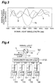
Fig. 3 shows an example of power spectra of output signal
light in a Raman amplifier employing the pumping light source
unit shown in Fig. 1;
Fig. 4 is a diagram showing a second embodiment of the
pumping light source unit according to the present invention;
Fig. 5 shows power spectra of pumping light supplied
from the pumping light source unit shown in Fig. 4;
Fig. 6 is a diagram showing a first configuration of
the wavelength variable pumping light source;
Fig. 7 is a diagram showing the configuration of a
modified example of the pumping light source unit according
to the second embodiment;
Fig. 8 is a diagram showing a second configuration of
the wavelength variable pumping light source;
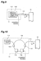
Fig. 9 is a diagram showing a third configuration of
the wavelength variable pumping light source;
Fig. 10 is a diagram showing a fourth configuration
of the wavelength variable pumping light source;
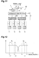
Fig. 11 is a diagram showing the configuration of a
fourth embodiment of the pumping light source unit according
to the present invention;
Fig. 12 shows spectra of pumping light supplied from
the pumping light source unit shown in Fig. 11;
Fig. 13 is a diagram showing the configuration of a
fourth embodiment of the pumping light source unit according
to the present invention;
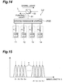
Fig. 14 is a diagram showing the configuration of a
fifth embodiment of the pumping light source unit according
to the present invention;
Fig. 15 shows spectra of pumping light supplied from
the pumping light source unit shown in Fig. 14;
Fig. 16 is a diagram showing the configuration of a
sixth embodiment of the pumping light source unit according
to the present invention;
Fig. 17 shows spectra of pumping light supplied from
the pumping light source unit shown in Fig. 16;
Fig. 18 is a diagram showing the configuration of a
seventh embodiment of the pumping light source unit according
to the present invention;
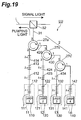
Fig. 19 is a diagram showing the configuration of an
eighth embodiment of the pumping light source unit according
to the present invention;
Figs. 20A and 20B are diagrams showing configurations
of a ninth embodiment of the pumping light source unit
according to the present invention;
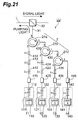
Fig. 21 is a diagram showing the configuration of a
tenth embodiment of the pumping light source unit according
to the present invention;
Fig. 22 is a diagram showing the configuration of an
eleventh embodiment of the pumping light source unit
according to the present invention;
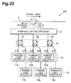
Fig. 23 is a diagram showing the configuration of the
pumping light source unit having a pumping light supply system
of a dual structure;
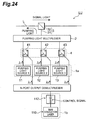
Fig. 24 is a diagram showing the configuration of a
twelfth embodiment of the pumping light source unit according
to the present invention;
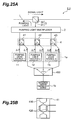
Figs. 25A and 25B are diagrams showing the
configurations of a thirteenth embodiment of the pumping
light source unit according to the present invention and
an optical switch;
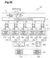
Fig. 26 is a diagram showing the configuration of a
fourteenth embodiment of the pumping light source unit
according to the present invention;
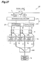
Fig. 27 is a diagram showing the configuration of a
fifteenth embodiment of the pumping light source unit
according to the present invention;
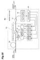
Fig. 28 is a diagram showing the configuration of a
first embodiment of the Raman amplifier according to the
present invention;
Fig. 29 is a diagram showing the configuration of a
second embodiment of the Raman amplifier according to the
present invention;
Fig. 30 is a diagram showing the configuration of a
third embodiment of the Raman amplifier according to the
present invention;
Fig. 31 is a diagram showing the configuration of a
fourth embodiment of the Raman amplifier according to the
present invention;
Fig. 32 is a diagram showing the configuration of a
first embodiment of the optical transmission system according
to the present invention;
Fig. 33 is a diagram showing the configuration of a
second embodiment of the optical transmission system
according to the present invention;
Fig. 34 is a block diagram showing the configuration
of a relay station in the optical transmission system shown
in Fig. 33;
Fig. 35 is a diagram showing the configuration of a
third embodiment of the optical transmission system according
to the present invention;
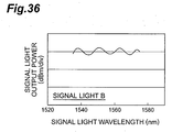
Fig. 36 shows a power spectrum obtained after Raman
amplification concerning signal light B;
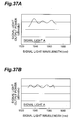
Figs. 37A and 37B show respective power spectra obtained
after Raman amplification concerning signal light A; and
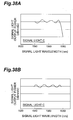
Figs. 38A and 38B show respective power spectra obtained
after Raman amplification concerning signal light C.
DETAILED DESCRIPTION OF THE PREFERRED EMBODIMENTS
In the following, embodiments of the pumping light
source unit, Raman amplifier, and optical transmission system
according to the present invention will be explained in detail
with reference to Figs. 1 to 19, 20A, 20B, 21 to 24, 25A,
25B, 26 to 36, and 37A to 38B. In the explanation of the
drawings, constituents identical to each other will be
referred to with numerals identical to each other without
repeating their overlapping descriptions. Ratios of
dimensions in the drawings do not always match those
explained.
Fig. 1 is a diagram showing the configuration of a first
embodiment of the pumping light source unit according to
the present invention. The pumping light source unit LU
according to the first embodiment is a light source unit
employed in a Raman amplifier for Raman-amplifying a
plurality of channels of signal light (WDM signal)
propagating through a Raman amplification optical fiber,
and supplies the Raman amplification optical fiber with a
plurality of channels of pumping light having respective
wavelengths different from each other.
The pumping light source unit LU comprises a pumping
light supply system 1 for supplying a plurality of channels
of pumping light, a pumping light multiplexer 2 for
multiplexing the plurality of channels of pumping light,
and an output structure 3 for outputting thus multiplexed
pumping light to an external optical transmission line L.
The pumping light supply system 1 generating a plurality
of channels of pumping light is constituted by a plurality
of pumping light sources outputting respective pumping light
components having wavelengths different from each other.
In the first embodiment shown in Fig. 1, the pumping
light supply system 1 comprises four pumping light sources,
i.e., a first pumping light source 11 for outputting pumping
light having a wavelength λ1, a second pumping light source
12 for outputting pumping light having a wavelength λ2 (λ2
> λ1), a third pumping light source 13 for outputting pumping
light having a wavelength λ3 (λ3 > λ2), and a fourth pumping
light source 14 for outputting pumping light having a
wavelength λ4 (λ4 > λ3). These pumping light sources are
wavelength variable pumping light sources configured such
that their outputting wavelengths λ1 to λ4 of pumping light
are variably controllable within their predetermined
wavelength ranges.
The wavelengths λ1 to λ4 of pumping light (four-channel
pumping light) respectively outputted from the four
wavelength variable pumping light sources 11 to 14 are
multiplexed in the pumping light multiplexer 2, so as to
become pumping light having a predetermined power spectrum
as a whole. Thus multiplexed pumping light is outputted by
way of the output structure 3 to the optical transmission
line 2 through which the signal light propagates. The output
structure 3 includes an output optical waveguide 31 and an
output multiplexer 32. As a consequence, the pumping light
multiplexed by the multiplexer 2 is transmitted through the
output optical waveguide 31 and then is multiplexed by the
output multiplexer 32 with the signal light propagating
through the optical transmission line L.
The pumping light supply system 1 in the pumping light
source unit LU functioning as a pumping light source of the
Raman amplifier is constituted by a plurality of pumping
light sources 11 to 14 outputting respective channel
wavelengths λ1 to λ4 of pumping light. Each of the pumping
light sources 11 to 14 is a wavelength variable pumping light
source. This configuration makes it possible to regulate
not only the power of each pumping light but also wavelengths
of pumping light outputted from the pumping light sources
11 to 14 as necessary, when adjusting the whole pumping light
spectrum outputted from the pumping light source unit LU.
In general, when employing a pumping light source unit
constituted by a plurality of pumping light sources in a
Raman amplifier, it becomes necessary to flatten the gain
spectrum within the amplification wavelength band, which
is a wide band, or the power spectrum of output signal light.
The power spectrum of signal light outputted from the Raman
amplifier subjected to adjustment is determined by the power
spectrum of pumping light supplied from the pumping light
source unit. Therefore, for adjusting the power spectrum
of signal light outputted from the Raman amplifier, it is
necessary to regulate the power spectrum of pumping light
outputted from the pumping light source unit.
Known as such a method of adjusting the pumping light
spectrum is one adjusting the pumping light power of each
channel outputted from the respective pumping light source
included in the pumping light source. However, such an
adjusting method may fail to attain sufficient
controllability for the pumping light spectrum. For example,
if the power of one of a plurality of pumping light sources
included in the pumping light source unit comes down, the
power spectrum of output signal light will greatly fall in
the vicinity of a signal light wavelength corresponding to
the channel wavelength of pumping light supplied by the
power-decreased pumping light source. In such a case, the
fall in the power spectrum of output signal light may not
fully be compensated for even if the power of pumping light
supplied by the pumping light sources other than the
power-decreased one is adjusted.
By contrast, the pumping light source unit LU comprising
a plurality of pumping light sources 11 to 14 each acting
as a wavelength variable pumping light source realizes a
pumping light source unit LU whose pumping light spectrum
controllability is improved so as to be able to respond
sufficiently to various changes including those in cases
where the pumping light spectrum greatly changes in all the
channels of pumping light outputted therefrom. Also, when
such a pumping light source unit LU is employed in a Raman
amplifier, the power fluctuation of output signal light
within the amplification wavelength band in the Raman
amplifier can fully be adjusted.
The pumping light spectrum adjustment and output signal
light spectrum flattening in the pumping light source unit
LU shown in Fig. 1 will now be explained with reference to
Figs. 2 and 3.
Fig. 2 shows power spectra of pumping light source
supplied from the pumping light source unit LU shown in Fig.
1, in which the abscissa indicates the pumping light
wavelength λ. At the time when the pumping light source unit
LU operates normally, four channels of pumping light having
pumping light wavelengths λ1 to λ4 respectively indicated
by broken lines in Fig. 2 are supplied from the four wavelength
variable pumping light sources 11 to 14.
Here, suppose that the power of third pumping light
source (wavelength variable pumping light source) 13 in the
pumping light sources 11 to 14 comes down, whereby the
wavelengths λ3 of pumping light stops being supplied. In
this case, the power spectrum of output signal light greatly
falls in the vicinity of a signal light wavelength
corresponding to the pumping light wavelength λ3 in the Raman
amplifier employing this pumping light source unit LU.
Fig. 3 shows output signal light spectra in a Raman
amplifier employing the pumping light source unit LU show
in Fig. 1, in which the abscissa indicates the channel
wavelength (nm) of signal light amplified by pumping light.
On the other hand, the ordinate indicates the signal light
output power (0.5 dBm/div) at each channel wavelength of
signal light.
When the pumping light source unit LU, to which the
four-channel pumping light having the wavelengths λ1 to λ4
is supplied, operates normally, the power of pumping light
supplied from each of the pumping light sources 11 to 14
is optimized, whereby the power spectrum of signal light
outputted from the Raman amplifier is substantially flattened
as indicated by broken line S. If the pumping light source
13 fails at that time, so that the channel wavelength λ3 of
pumping light stops being supplied, the amplification gain
and signal light output power will fall greatly in the vicinity
of a signal light wavelength (near a wavelength of 1565 nm
in Fig. 3) corresponding to the pumping light power wavelength
λ3 in'the output signal light power spectrum as indicated
by broken line Sd.
In the pumping light source unit LU according to the
first embodiment, by contrast, three channels of pumping
light having respective wavelengths of λ1, λ2, λ4 supplied
from the remaining three unfailing wavelength variable
pumping light sources 11, 12, and 14 change their pumping
light wavelengths along the wavelength axis so as to approach
the wavelength λ3, thereby being adjusted to λ1', λ2', λ4'
as indicated by solid lines in Fig. 2, respectively. This
adjusts the power spectrum as seen from all the channels
of pumping light supplied from the pumping light source unit
LU, whereby the power spectrum of signal light outputted
from the Raman amplifier is flattened to the utmost as
indicated by solid line S' in Fig. 3. Specifically, it is
preferred that the remaining three unfailing wavelength
variable pumping light sources 11, 12, and 14 be
wavelength-controlled such that the power fluctuation per
channel of Raman-amplified signal light becomes 2 dB or less .
The pumping light source unit LU according to the first
embodiment utilizing a plurality of wavelength variable
pumping light sources 11 to 14 exhibits an excellent
controllability for output signal light spectra changed
within the amplification wavelength band as mentioned above.
Such a pumping light source unit LU is also effective in
various adjustments to output signal light spectra other
than the power spectrum flattening of output signal light.
For example, when output signal light spectra in at
least two different wavelength bands are flattened so as
be used as an amplification wavelength band (by utilizing
at least two Raman amplifiers having the same configuration) ,
the pumping light source unit LU having the above-mentioned
structure can change the amplification wavelength band, which
is a band where an output signal light spectrum is flattened,
by shifting the pumping light spectrum as a whole with respect
to the wavelength.
Though all of the plurality of pumping light sources
11 to 14 included in the pumping light supply system 1 are
used as a wavelength variable pumping light source in the
pumping light source unit LU shown in Fig. 1, the number
of wavelength variable pumping light sources is flexible
so that, as long as one of the plurality of pumping light
sources is a wavelength variable pumping light source, the
others may have their respective fixed channel wavelengths
of pumping light. The number of such wavelength variable
light sources or the ratio of wavelength variable pumping
light sources in the pumping light supply system may be set
as appropriate according to the channel interval (wavelength
interval) of pumping light, the output signal light
controllability required for the Raman amplifier employing
the pumping light source unit, and the like.
In the pumping light source unit LU shown in Fig. 1,
the output structure 3 for outputting the pumping light to
the optical transmission line L comprises not only the output
optical waveguide 31, but also the output multiplexer 32
for multiplexing the pumping light and signal light. As for
the output multiplexer 32, only the output optical waveguide
31 may be disposed on the pumping light source unit LU side
without providing a multiplexer there, so as to connect the
output optical waveguide 31 of the pumping light source unit
LU to a multiplexer disposed on the optical transmission
line L side. Alternatively, the output end of the pumping
light multiplexer 2 may be included in the output structure
as it is.
Though Fig. 1 shows a configuration in which the pumping
light from the output optical waveguide 31 is guided to the
optical transmission line L in the direction opposite from
the signal light transmission direction, the pumping light
propagating direction may be a forward direction coinciding
with the signal light transmission direction according to
the configuration of Raman amplifier and the like.
Fig. 4 is a diagram showing the configuration of a second
embodiment of the pumping light source unit according to
the present invention. As in the first embodiment, the
pumping light source unit LU according to the second
embodiment comprises four wavelength variable pumping light
sources for outputting respective channel wavelengths λ1 to
λ4 (λ1 < λ2 < λ3 < λ4) of pumping light as a plurality of pumping
light sources constituting a pumping light supply system.
As a pumping light multiplexer 2 for multiplexing
respective pumping light components outputted from the
pumping light sources 11 to 14, a wavelength multiplexer
21 for multiplexing pumping light in terms of wavelength
is provided.
The configuration of pumping light sources 11 to 14
will now be explained with reference to the first pumping
light source 11 by way of example. In the second embodiment,
the first wavelength variable pumping light source 11 has
a first semiconductor laser 110 suitable for pumping laser
as its pumping light generating source. Disposed between
the semiconductor laser 110 and the wavelength multiplexer
21 is an optical waveguide 111 for guiding the pumping light
from the pumping light source 11 to the wavelength multiplexer
21. Disposed at a predetermined position on the optical
waveguide 111 is a resonance grating 112 for reflecting light
outputted from the semiconductor laser 110. As the resonance
grating, a Bragg grating reflecting light having a Bragg
wavelength is preferred. The pumping light source 11
preferably comprises a channel wavelength adjusting system
for adjusting the reflection wavelength of the resonance
grating 112. Consequently, from the semiconductor laser 110
and the resonance grating 112 disposed on the optical
waveguide 111, an external resonator type wavelength variable
laser unit is obtained as the wavelength variable pumping
light source 11 adapted to control the wavelength of pumping
light outputted therefrom.
In the second embodiment, all of the four pumping light
sources 11 to 14 are wavelength variable pumping light sources.
The three pumping light sources 12 to 14 have the same
configuration as that of the first wavelength variable
pumping light source 11 mentioned above.
Namely, the second wavelength variable pumping light
source 12 is an external resonator type wavelength variable
laser unit comprising a second semiconductor laser 120
suitable for pumping laser, a resonance grating 122 disposed
on the optical waveguide 121, and a channel wavelength
adjusting system for adjusting the reflection wavelength
of the resonance grating. The third wavelength variable
pumping light source 13 is an external resonator type
wavelength variable laser unit comprising a third
semiconductor laser 130 suitable for pumping laser, a
resonance grating 132 disposed on the optical waveguide 131,
and a channel wavelength adjusting system for adjusting the
reflection wavelength of the resonance grating. The fourth
wavelength variable pumping light source 14 is an external
resonator type wavelength variable laser unit comprising
a fourth semiconductor laser 140 suitable for pumping laser,
a resonance grating 142 disposed on the optical waveguide
141, and a channel wavelength adjusting system for adjusting
the reflection wavelength of the resonance grating.
The respective channel wavelengths λ1 to λ4 of pumping
light outputted from the four wavelength variable pumping
light sources 11 to 14 are multiplexed by the wavelength
multiplexer 21 acting as the pumping light multiplexer 2,
while exhibiting a predetermined power spectrum in a
wavelength band including all the channels. Thus
multiplexed pumping light is outputted to an optical
transmission line L by way of an output structure 3 constituted
by an output optical waveguide 31 and an output multiplexer
32.
By variably controlling wavelengths of light reflected
by the resonance gratings 112 to 142, the pumping light source
unit LU according to the second embodiment can efficiently
control the wavelengths λ1 to λ4 of pumping light outputted
from the four wavelength variable pumping light sources 11
to 14, which are external resonator type laser units.
Fig. 5 shows power spectra of pumping light supplied
from the pumping light source unit LU according to the second
embodiment shown in Fig. 4. Fig. 5 shows an example in which
the respective channel wavelengths of pumping light are
adjusted to wavelengths λ1', λ2', and λ4' (indicated by broken
lines) when the power of channel wavelength λ3 among channel
wavelengths λ1 to λ4 (indicated by dotted lines) of pumping
light comes down. It is preferred that the remaining three
unfailing wavelength variable pumping light sources 11, 12,
and 14 be wavelength-controlled such that the power
fluctuation per channel of Raman-amplified signal light
becomes 2 dB or less in the second embodiment as well.
When the external resonator type laser unit having the
above-mentioned structure is employed as a wavelength
variable pumping light source, the resonance grating for
external resonance of pumping light is preferably a Bragg
grating. Various forms of grating can be employed as a
specific configuration of Bragg grating.
Fig. 6 is a diagram showing an example of first
configuration of the wavelength variable pumping light source
employed in the pumping light source unit LU shown in Fig.
4. Fig. 6 shows the configuration of the first wavelength
variable pumping light source 11 alone among the four pumping
light sources 11 to 14. The other pumping light sources 12
to 14 have the same structure as that of the first wavelength
variable pumping light source 11 shown in Fig. 6.
The first wavelength variable pumping light source 11
is an external resonator type wavelength variable laser unit
comprising a first semiconductor laser 110, and a resonance
grating 112 disposed on the optical waveguide 111; and
generating the channel wavelength λ1 of pumping light due
to the external resonance between the semiconductor laser
110 and resonance grating 112.
As the optical waveguide 111 for guiding the pumping
light outputted from the pumping light source 11 to the
wavelength multiplexer 21, Fig. 6 shows an optical fiber
111a disposed between the semiconductor laser 110 and the
wavelength multiplexer 21. A predetermined part of the'
optical fiber 111a is formed with a fiber Bragg grating 112a
as a resonance grating 112.
The pumping light source 11 further comprises a channel
wavelength adjusting system 112b for adjusting the reflection
wavelength of the fiber Bragg grating 112a. The channel
wavelength adjusting system 112b is controlled by a control
signal from the outside. As a consequence, the reflection
wavelength of the resonance grating yielding the channel
wavelength λ1 of pumping light is adjusted.
In a simple configuration, such a fiber grating can
realize both a configuration of external resonance in the
pumping light source 11, which is a wavelength variable laser
unit, and a configuration of the optical waveguide 111 for
outputting pumping light from the pumping light source 11
to the pumping light multiplexer 21.
Employable as the channel wavelength adjusting system
112b is stress applying means, for example. By applying a
predetermined stress to the optical fiber 111a, the stress
applying means causes the optical fiber 111a to
expand/contract. As a result, the grating period of the fiber
Bragggrating 112a changes, whereby the reflection wavelength
of resonance grating 112 is adjusted. The channel wavelength
λ1 of pumping light supplied from the pumping light source
11 is controlled by the external resonator constituted by
the resonance grating 112 with thus adjusted reflection
wavelength and the semiconductor laser 110.
Also employable as the channel wavelength adjusting
system 112b is heating means. By heating the optical fiber
111a, the heating means changes the grating refractive index
of fiber Bragg grating 112a (the refractive index of the
core region in the optical fiber 111a formed with the fiber
Bragg grating 112a). This changes the reflection wavelength
of resonance grating 112, thereby controlling the channel
wavelength of pumping light supplied from the pumping light
source 11.
When controlling the channel wavelength of pumping
light supplied from the pumping light source by utilizing
channel wavelength adjusting means such as a resonance
grating as shown in Fig. 6, transmission wavelength
characteristics of light in the pumping light multiplexer
2 such as the wavelength multiplexer 21 might become
problematic.
Fig. 5 shows transmission wavelength characteristics
T1 to T4 as an example of transmission wavelength
characteristics (multiplexing wavelength characteristics)
in the wavelength multiplexer 21 with respect to channel
wavelengths λ1 to λ4 of pumping light before wavelength
adjustment, and channel wavelengths λ1', λ2', and λ4' of
pumping light after wavelength adjustment.
In general, these transmission wavelength
characteristics T1 to T4 are optimized such that the channel
wavelengths λ1 to λ4 of pumping light are favorablymultiplexed
at the time when the 'pumping light source unit LU operates
normally. However, when the power of channel wavelength λ3
comes down and the other channel wavelengths are changed
to λ1', λ2', and λ4', respectively; in order to adjust the
pumping light spectrum in response thereto, there are cases
where the wavelength multiplexer 21 fails to attain a
sufficient transmission characteristic with respect to
pumping light yielding a large amount of change in the channel
wavelength.
For example, concerning the channel wavelength λ4 of
pumping light near the channel wavelength λ3 of pumping light
whose power has come down, the amount of change in channel
wavelength from λ4 to λ4' due to the wavelength adjustment
is greater as shown in Fig. 5. When there is a possibility
of greatly changing the channel wavelength of pumping light
as such, the wavelength multiplexer 21 preferably comprises
a structure adapted to adjust transmission wavelength
characteristics in order to secure a sufficient transmission
characteristic with respect to each channel of pumping light
in the pumping light multiplexer 2.
Fig. 7 is a diagram showing an example of configuration
of a pumping light source unit having a pumping light
multiplexer adapted to adjust a transmission wavelength
characteristic. In the configuration of Fig. 7, the
wavelength multiplexer 21 is provided with a transmission
characteristic adjusting system 22 for adjusting the
transmission characteristic of the former. The wavelength
multiplexer 21 and the transmission characteristic adjusting
system 22 constitute a pumping light multiplexer 2 adapted
to adjust a transmission wavelength characteristic. The
transmission characteristic adjusting system 22 is
controlled by a control signal from the outside. As a
consequence, the transmission characteristic in the pumping
light multiplexer 2 is optimally controlled in response to
changes in the respective channel wavelengths λ1 to λ4 of
pumping light outputted from the pumping light sources 11
to 14.
Without being restricted to the external resonator type
wavelength variable laser unit utilizing a fiber Bragg
grating shown in Fig. 6, various pumping light sources are
applicable as wavelength variable pumping light sources
employed in the pumping light source unit.
Fig. 8 is a diagram showing a second configuration of
wavelength variable pumping light source employable in the
pumping light source unit shown in Fig. 4. In this case,
the wavelength variable pumping light source 11 comprises
a first semiconductor laser 110, a resonance grating 112
disposed on an optical waveguide 111, and a channel wavelength
adjusting system as an electric field applying means 112d,
whereas the wavelength variable pumping light source 11 is
an external resonator wavelength variable laser unit
generating the channel wavelength λ1' of pumping light due
to the external resonance utilizing the first semiconductor
laser 110 and resonance grating 112.
In Fig. 8, as the optical waveguide 111 for guiding
the pumping light outputted from the pumping light source
11 to the wavelength multiplexer 21, an optical fiber 111b,
an optical waveguide 111c, and an optical fiber 111d are
disposed successively from the semiconductor laser 110 toward
the wavelength multiplexer 21.
Among these optical waveguides, the optical waveguide
111c is an optical waveguide formed on a predetermined
substrate from a material having an electrooptic effect.
Also, a predetermined part of the optical waveguide 111c
is formed with a Bragg grating 112c as a resonance grating
112.
The electric field applying means acting as a channel
wavelength adjusting system comprises a pair of electrodes
112d disposed on the same substrate across the Bragg grating
112c. The electrodes 112d are controlled by a control signal
from the outside. As a consequence, the reflection
wavelength in the resonance grating 112 yielding the channel
wavelength λ1 of pumping light is variably controlled.
Namely, when the electrodes 112d acting as the electric field
applying means applies an electric field having a
'predetermined intensity to the optical waveguide having an
electrooptic effect, the reflection wavelength of Bragg
grating 112c changes. This can variably control the channel
wavelength λ1 of pumping light supplied from the pumping light
source 11.
In a simple configuration, such a grating can also
realize both a configuration of external resonance in the
pumping light source 11, which is a wavelength variable laser
unit, and a configuration of the optical waveguide 111 for
outputting pumping light from the pumping light source 11
to the pumping light multiplexer 21.
Fig. 9 is a diagram showing a third configuration of
wavelength variable pumping light source employable in the
pumping light source unit shown in Fig. 4. This wavelength
variable pumping light source 11 comprises a first
semiconductor laser 110, and a heating means 113 for adjusting
the temperature of a chip of the semiconductor laser 110
as a channel wavelength adjusting system. The heating means
113 is controlled by a control signal from the outside. As
a consequence, the oscillation wavelength in the
semiconductor laser 110 yielding the channel wavelength λ1
of pumping light is variably controlled.
Fig. 10 is a diagram showing a fourth configuration
of wavelength variable pumping light source employable in
the pumping light source unit shown in Fig. 4. This
wavelength variable pumping light source 11 is a fiber ring
wavelength variable laser unit generating the channel
wavelength λ1 of pumping light by utilizing a first pumping
laser 114 and a ring-shaped optical fiber 115.
The ring-shaped optical fiber 115 includes a
rare-earth-doped optical fiber having an optically
amplifying function. A wave length multiplexer 116 is placed
at a predetermined position of the ring-shaped optical fiber
115 on the pumping laser 114 side. The light outputted from
the pumping laser 114 is supplied to the ring-shaped optical
fiber 115 by way of the wavelength multiplexer 116, and is
amplified in the ring-shaped optical fiber 115, which is
a rare-earth-doped optical fiber. At predetermined
positions on the ring-shaped optical fiber 115, an optical
isolator 118 and a bandpass filter 119 are placed, whereby
the channel wavelength λ1 of pumping light generated in the
pumping light source 11 is determined according to the
transmission wavelength characteristic of the bandpass
filter 119.
At a predetermined position of the ring-shaped optical
fiber 115 on the wavelength multiplexer 21 side, a branching
device 117 for branching light at a predetermined ratio is
placed. The channel wavelength λ1 of light amplified by the
ring-shaped optical fiber 115 is branched by the branching
device 117 to an optical waveguide 111, so as to be outputted
to the wavelength multiplexer 21 as pumping light.
In the wavelength variable pumping light source 11 of
Fig. 10, a wavelength variable bandpass filter (included
in a channel wavelength adjusting system) adapted to change
its transmission wavelength is utilized as the bandpass
filter 119 for determining the channel wavelength λ1 of light
amplified by the ring-shaped optical fiber 115. The bandpass
filter 119 is controlled by a control signal from the outside.
As a consequence, the channel wavelength λ1 of pumping light
is variably controlled in the ring-shaped optical fiber 115.
As the bandpass filter 119 having a variable
transmission wavelength characteristic, an optical filter
made of a dielectric multilayer film is utilizable. The
dielectric multilayer film filter can control its
transmission wavelength characteristic variably and easily
by rotating the angle of filter with respect to the optical
path of the light to be transmitted therethrough. Bandpass
filters other than the dielectric multilayer film filters
can also be utilized.
Embodiments of the pumping light source unit will
further be explained.
Fig. 11 is a diagram showing the configuration of a
third embodiment of the pumping light source unit according
to the present invention. The pumping light source unit LU
according to the third embodiment comprises four wavelength
variable pumping light sources 11 to 14 for outputting
respective channel wavelengths λ1 to λ4 (λ1 < λ2 < λ3 < λ4)
of pumping light as a plurality of pumping light sources
constituting a pumping light supply system. The
configuration of each of the pumping light sources 11 to
14 is the same as that of the second embodiment shown in
Fig. 4.
A pumping light multiplexer 2 for multiplexing
respective pumping light components outputted from the
pumping light sources 11 to 14 is constituted by two
polarization multiplexers 23a, 23b each multiplexing two
channels of pumping light having respective wavelengths
adjacent each other, and a wavelength multiplexer 21 for
multiplexing the pumping light in terms of wavelength.
The channel wavelengths λ1, λ2 of pumping light adjacent
each other outputted from the pumping light sources 11, 12
among the four wavelength variable pumping light sources
11 to 14 are polarization-multiplexed by the polarization
multiplexer 23a. The channel wavelengths λ3, λ4 of pumping
light adjacent each other outputted from the pumping light
sources 13, 14 among the four wavelength variable pumping
light sources 11 to 14 are polarization-multiplexed by the
polarization multiplexer 23b.
The pumping light having the channel wavelengths λ1,
λ2 outputted from the polarization multiplexer 23a and the
pumping light having the channel wavelengths λ3, λ4 outputted
from the polarization multiplexer 23b are multiplexed by
the wavelength multiplexer 21, whereby pumping light having
a predetermined pumping light spectrum as a whole is outputted
from the wavelength multiplexer 21. Thus multiplexed
pumping light is outputted to an optical transmission line
L by way of an output structure constituted by an output
optical waveguide 31 and an output multiplexer 32.
In the case where the polarization multiplexers 23a,
23b are employed in the pumping light multiplexer 2 for
multiplexing the pumping light as such, it is unnecessary
to adjust transmission characteristics in the polarization
multiplexing of pumping light effected by the polarization
multiplexers 23a, 23b even when the respective channel
wavelengths of pumping light supplied from the individual
pumping light sources 11 to 14 have changed. As a consequence,
pumping light can easily be multiplexed when the pumping
light multiplexer 2 is constituted by a combination of a
plurality of polarization multiplexers 23a, 23b and the
wavelength multiplexer 21.
Fig. 12 shows power spectra of pumping light supplied
from the pumping light source unit LU shown in Fig. 11. As
with Fig. 5, Fig. 12 shows an example in which the channel
wavelengths λ1, λ2, and λ4 in the channel wavelengths λ1 to
λ4 are adjusted to λ1', λ2', and λ4' when the power of channel
wavelength λ3 comes down. Fig. 12 also shows respective
transmission wavelength characteristics Ta, Tb of the
wavelength multiplexer 21 with respect to the pumping light
components outputted from the polarization multiplexers 23a,
23b.
Preferably, the transmission wavelength
characteristics Ta, Tb of the wavelength multiplexer 21 extend
over a relatively large wavelength range as shown in Fig.
12, since the pumping light is polarization-multiplexed in
the polarization multiplexers 23a, 23b in its upstream stage.
In this case, a sufficient transmission characteristic is
obtained even when channel wavelength of pumping light
fluctuates greatly to a certain extent.
Fig. 13 is a diagram showing the configuration of a
fourth embodiment of the pumping light source unit according
to the present invention. The pumping light source unit LU
according to the fourth embodiment comprises four wavelength
variable pumping light sources 11 to 14 for outputting
respective channel wavelengths λ1 to λ4 (λ1 < λ2 < λ3 < λ4)
of pumping light as a plurality of pumping light sources
constituting a pumping light supply system. The
configuration of each of the pumping light sources 11 to
14 is the same as that of the second embodiment shown in
Fig. 4.
A pumping light multiplexer 2 for multiplexing
respective pumping light components outputted from the
pumping light sources 11 to 14 comprises two polarization
multiplexers 23a, 23b each multiplexing two channels of
pumping light having respective wavelengths adjacent each
other, and a wavelength multiplexer 21 for multiplexing the
pumping light in terms of wavelength. The pumping light
multiplexer 2 according to the fourth embodiment further
comprises depolarizers 24a, 24b placed between the respective
polarization multiplexers 23a, 23b and the wavelength
multiplexer 21.
The channel wavelengths λ1, λ2 of pumping light adjacent
each other outputted from the pumping light sources 11, 12
among the four wavelength variable pumping light sources
11 to 14 are polarization-multiplexed by the polarization
multiplexer 23a, and thus multiplexed light is depolarized
by the depolarizer 24a. The channel wavelengths λ3, λ4 of
pumping light adjacent each other outputted from the pumping
light sources 13, 14 are polarization-multiplexed by the
polarization multiplexer 23b, and thus multiplexed light
is depolarized by the depolarizer 24b.
The pumping light having the channel wavelengths λ1,
λ2 outputted from the polarization multiplexer 23a by way
of the polarizer 24a and the pumping light having the channel
wavelengths λ3, λ4 outputted from the polarization
multiplexer 23b by way of the polarizer 24b are multiplexed
by the wavelength multiplexer 21, whereby pumping light
having a predetermined pumping light spectrum as a whole
is outputted from the wavelength multiplexer 21. Thus
multiplexed pumping light is outputted to an optical
transmission line L by way of an output structure constituted
by an output optical waveguide 31 and an output multiplexer
32.
In the configuration employing the polarization
multiplexers 23a, 23b in the pumping light multiplexer 2,
polarization multiplexing is carried out for two different
channels of pumping light, whereby the state of polarization
may differ between the pumping light
polarization-multiplexed by the polarization multiplexer
23a and the pumping light polarization-multiplexed by the
polarization multiplexer 23b. In this case, there is a
possibility of Raman amplification gain varying under the
influence of the state of polarization of pumping light.
By contrast, a configuration in which the depolarizers 24a,
24b are placed in the downstream stage of the polarization
multiplexers 23a, 23b as in the pumping light source unit
according to the fourth embodiment effectively reduces the
influence of polarization dependence of Raman amplification
gain.
Fig. 14 is a diagram showing the configuration of a
fifth embodiment of the pumping light source unit according
to the present invention. The pumping light source unit LU
according to the fifth embodiment comprises four wavelength
variable pumping light sources 11 to 14 for outputting
respective channel wavelengths λ1 to λ4 (λ1 < λ2 < λ3 < λ4)
of pumping light as a plurality of pumping light sources
constituting a pumping light supply system. The
configuration of each of the pumping light sources 11 to
14 is the same as that of the second embodiment shown in
Fig. 4.
Also, in the fifth embodiment, an arrayed waveguide
grating (AWG) 25 is provided as a pumping light multiplexer
2 for multiplexing respective pumping light components
outputted from the pumping light sources 11 to 14.
The channel wavelengths λ1 to λ4 of pumping light
outputted from the four wavelength variable pumping light
sources 11 to 14 are multiplexed by the AWG 25 acting as
the pumping light multiplexer 2, whereby pumping light having
a predetermined pumping light spectrum as a whole is outputted
from the pumping light multiplexer 2. Thus multiplexed
pumping light is outputted to an optical transmission line
L by way of an output structure constituted by an output
optical waveguide 31 and an output multiplexer 32.
Fig. 15 shows power spectra of pumping light supplied
from the pumping light source unit LU shown in Fig. 14. Fig.
15 shows an example in which the channel wavelengths λ1 to
λ4 of pumping light are changed to wavelengths λ1' to λ4'
shifted as a whole. Fig. 15 also shows the transmission
wavelength characteristic T of the AWG 25.
The AWG 25 has a periodic transmission wavelength
characteristic T with respect to channel wavelength λ.
Therefore, if the channel interval (wavelength interval)
of respective channel wavelengths λ1 to λ4 of pumping light
supplied from the pumping light sources 11 to 14 or the amount
of change in channel wavelength upon changing the channel
wavelengths to wavelengths λ1' to λ4', respectively,
coincides with the wavelength period of transmission
characteristic T in the AWG 25, the respective pumping light
components from the pumping light sources 11 to 14 can be
multiplexed favorably even when the channel wavelengths of
pumping light are changed as a whole. Such a multiplexing
characteristic is effective in particular when individual
channel wavelengths of pumping light are shifted as a whole
as shown in Fig. 15, so as to shift the amplification wavelength
band in a Raman amplifier.
Fig. 16 is a diagram showing the configuration of a
sixth embodiment of the pumping light source unit according
to the present invention. The pumping light source unit LU
according to the sixth embodiment comprises two wavelength
variable pumping light sources 11, 12 for outputting
respective channel wavelengths λ1, λ2 (λ1 < λ2) of pumping
light as a plurality of pumping light sources constituting
a pumping light supply system. The configuration of each
of the pumping light sources 11, 12 is the same as that of
the second embodiment shown in Fig. 4.
In the sixth embodiment, an interleaver 26 is provided
as a pumping light multiplexer 2 for multiplexing respective
pumping light components outputted from the pumping light
sources 11, 12.
The channel wavelengths λ1, λ2 of pumping light
respectively outputted from the two wavelength variable
pumping light sources 11, 12 are multiplexed by the
interleaver 26 acting as the pumping light multiplexer 2,
whereby pumping light having a predetermined pumping light
spectrum as a whole is outputted from the interleaver 26.
Thus multiplexed pumping light is outputted to an optical
transmission line L by way of an output structure constituted
by an output optical waveguide 31 and an output multiplexer
32.
Fig. 17 shows power spectra of pumping light supplied
from the pumping light source unit LU shown in Fig. 16. Fig.
17 shows an example in which the channel wavelengths λ1, λ2
of two-channel pumping light are shifted to wavelengths λ1',
λ2' as a whole. Fig. 17 also shows transmission
characteristics T1 (solid line), T2 (broken line) of the
interleaver 26 with respect to respective pumping light
components outputted from the pumping light sources 11, 12.
As shown in Fig. 17, the interleaver 26 has periodic
transmission wavelength characteristics T1, T2 with respect
to channel wavelength λ. Also, the transmission wavelength
characteristics T1, T2 have a shorter wavelength period as
compared with those of AWG. Therefore, the interleaver 26
can respond to a shorter channel interval (wavelength
interval) of pumping light or a smaller shift amount (amount
of change) in channel wavelengths as compared with the case
where AWG is employed as the pumping light multiplexer 2.
Fig. 18 is a diagram showing the configuration of a
seventh embodiment of the pumping light source unit according
to the present invention. The pumping light source unit LU
according to the seventh embodiment comprises eight
wavelength variable pumping light sources 11 to 18 for
outputting respective channel wavelengths λ1 to λ8 (λ1 < λ2
< λ3 < λ4 < λ5 < λ6 < λ7 < λ8) of pumping light as a plurality
of pumping light sources constituting a pumping light supply
system. The configuration of each of the pumping light
sources 11 to 18 is the same as that of the second embodiment
shown in Fig. 4.
Also, in the seventh embodiment, two arrayed waveguide
gratings (AWGs) 25a, 25b and an interleaver 26 are provided
as a pumping light multiplexer 2 for multiplexing respective
pumping light components outputted from the pumping light
sources 11 to 18.
Every other channel wavelengths λ1, λ3, λ5, λ7 of pumping
light outputted from the pumping light sources 11, 13, 15,
17 among the eight wavelength variable pumping light sources
11 to 18 are multiplexed by the AWG 25a. Every other channel
wavelengths λ2, λ4, λ6, λ8 of pumping light outputted from
the pumping light sources 12, 14, 16, 18 are multiplexed
by the AWG 25b.
Further, the pumping light having channel wavelengths
λ1, λ3, λ5, λ7 outputted from the AWG 25a and the pumping light
having channel wavelengths λ2, λ4, λ6, λ8 outputted from the
AWG 25b are multiplexed by the interleaver 26, whereby pumping
light having a predetermined pumping light spectrum as a
whole is outputted from the interleaver 26. Thus multiplexed
pumping light is outputted to an optical transmission line
L by way of an output structure constituted by an output
optical waveguide 31 and an output multiplexer 32.
When a single interleaver is employed as the pumping
light multiplexer 2 as shown in Fig. 16, the number of pumping
light components which can be multiplexed is limited to 2.
In the configuration in which the AWGs 25a, 25b in the upstream
stage and the interleaver 26 in the downstream stage are
combined with each other as shown in Fig. 18, a given number
of channels of pumping light can be multiplexed while
utilizing a multiplexing characteristic of the interleaver
adapted to respond to pumping light exhibiting a shorter
channel interval (wavelength interval) or a smaller amount
of wavelength change.
Fig. 19 is a diagram showing the configuration of an
eighth embodiment of the pumping light source unit according
to the present invention. The pumping light source unit LU
according to the eighth embodiment comprises four (N)
wavelength variable pumping light sources 11 to 14 for
outputting respective channel wavelengths λ1 to λ4 (λ1 < λ2
< λ3 < λ4) of pumping light as a plurality of pumping light
sources constituting a pumping light supply system. The
configuration of each of the pumping light sources 11 to
14 is the same as that of the second embodiment shown in
Fig. 4.
Also, in the eighth embodiment, three (N-1) 3-port
optical circulators 27a, 27b, 27c are provided as a pumping
light multiplexer 2 for multiplexing respective pumping light
source components outputted from the pumping light sources
11 to 14. These optical circulators 27a, 27b, 27c are
connected in three stages (N-1 stages) so that the respective
pumping light components outputted from the pumping light
sources 11 to 14, which are four (N) external resonator type
laser units, are multiplexed successively.
Namely, in the optical circulator 27c in the first stage,
an optical waveguide 141 from the pumping light source 14
is connected to the first port, an optical waveguide 131
from the pumping light source 13 is connected to the second
port, and an optical waveguide 430 is connected to the third
port. In the optical circulator 27b in the second stage,
the optical waveguide 430 from the optical circulator 27c
is connected to the first port, an optical waveguide 121
from the pumping light source 12 is connected to the second
port, and an optical waveguide 420 is connected to the third
port. In the optical circulator 27a in the third stage, the
optical waveguide 420 from the optical circulator 27b is
connected to the first port, an optical waveguide 111 from
the pumping light source 11 is connected to the second port,
and an output optical waveguide 31 is connected to the third
port.
Placed between the resonance grating 112 of the pumping
light source 11 and the optical circulator 27a are a reflection
grating 412 for reflecting the channel wavelength λ2 of
pumping light, a reflection grating 413 for reflecting the
channel wavelength λ3 of pumping light, and a reflection
grating 414 for reflecting the channel wavelength λ4 of
pumping light. Placed between the resonance grating 122 of
the pumping light source 12 and the optical circulator 27b
are a reflection grating 423 for reflecting the channel
wavelength λ3 of pumping light and a reflection grating 424
for reflecting the channel wavelength λ4 of pumping light.
Placed between the resonance grating 132 of the pumping light
source 13 and the optical circulator 27c is a reflection
grating 434 for reflecting the channel wavelength λ4 of
pumping light. Preferably, each reflection grating is a
Bragg grating reflecting its corresponding channel
wavelength of light by substantially 100%.
In the foregoing configuration, the channel wavelength
λ1 of pumping light supplied from the pumping light source
11 is outputted to the output optical waveguide 31 by way
of the optical circulator 27a.
The channel wavelength λ2 of pumping light supplied
from the pumping light source 12 is outputted to the optical
waveguide 31 by way of the optical circulator 27b, optical
waveguide 420, and optical circulator 27a. Then, the channel
wavelength λ2 of pumping light is reflected by the reflection
grating 412, so as to be fed into the optical circulator
27a again, and is outputted to the output optical waveguide
31 by way of the optical circulator 27a.
The channel wavelength λ3 of pumping light supplied
from the pumping light source 13 is outputted to the optical
waveguide 121 by way of the optical circulator 27c, optical
waveguide 430, and optical circulator 27b. Then, the channel
wavelength λ3 of pumping light is reflected by the reflection
grating 423, so as to be fed into the optical circulator
27b again, and is outputted to the optical waveguide 111
by way of the optical circulator 27b, optical waveguide 420,
and optical circulator 27a. Further, the channel wavelength
λ3 of pumping light is reflected by the reflection grating
413, so as to be fed into the optical circulator 27a again,
and is outputted to the output optical waveguide 31 by way
of the optical circulator 27a.
The channel wavelength λ4 of pumping light supplied
from the pumping light source 14 is outputted to the optical
waveguide 131 by way of the optical circulator 27c. The
channel wavelength λ4 of pumping light is reflected by the
reflection grating 434, so as to be fed into the optical
circulator 27c again, and is outputted to the optical
waveguide 121 by way of the optical circulator 27c, optical
waveguide 430, and optical circulator 27b. Further, the
channel wavelength λ4 of pumping light is reflected by the
reflection grating 424, so as to be fed into the optical
circulator 27b again, and is outputted to the optical
waveguide 111 by way of the optical circulator 27b, optical
waveguide 420, and optical circulator 27a. Thereafter, the
channel wavelength λ4 of pumping light is reflected by the
reflection grating 414, so as to be fed into the optical
circulator 27a again, and is outputted to the output optical
waveguide 31 by way of the optical circulator 27a.
As in the foregoing, the respective channel wavelengths
λ1 to λ4 of pumping light outputted from four wavelength
variable pumping light sources 11 to 14 are multiplexed by
three 3-port optical circulators 27a, 27b, 27c constituting
the pumping light multiplexer 2, whereby pumping light having
a predetermined pumping light spectrum as a whole is outputted
from the pumping light multiplexer 2. Thus multiplexed
pumping light is outputted to an optical transmission line
L by way of an output structure 3 constituted by the output
optical waveguide 31 and an output multiplexer 32.
Thus, a configuration employing (N-1) 3-port optical
circulators as the pumping light multiplexer 2 with respect
to N pumping light sources can favorably multiplex respective
pumping light components from the pumping light sources as
well. As the reflection gratings, various gratings are
employable as with the resonance gratings in pumping light
sources.
Preferably, the wavelength of light reflected by each
reflection grating is variably controlled in synchronization
with the reflection wavelength of the respective resonance
grating when its corresponding pumping light source is a
wavelength variable pumping light source. In the eighth
embodiment, since all of the pumping light sources 11 to
14 are wavelength variable pumping light sources, a channel
wavelength adjusting system variably controlling all the
reflection gratings as mentioned above is provided. As a
consequence, the respective pumping light source components
supplied from the pumping light sources 11 to 14 can
efficiently be guided to the output optical waveguide 31.
Specifically, it is preferred that the reflection
grating 412 for reflecting the channel wavelength λ2 of
pumping light be controlled in synchronization with the
resonance grating 122 of the pumping light source 12.
Preferably, the reflection gratings 413, 423 for reflecting
the channel wavelength λ3 of pumping light are controlled
in synchronization with the resonance grating 132 of the
pumping light source 13. Preferably, the reflection
gratings 414, 424, 434 for reflecting the channel wavelength
λ4 of pumping light are controlled in synchronization with
the resonance grating 142 of the pumping light source 14.
Fig. 20A is a diagram showing the configuration of a
ninth embodiment of the pumping light source unit according
to the present invention. The pumping light source unit LU
according to the ninth embodiment comprises four (N)
wavelength variable pumping light sources 11 to 14 for
outputting respective channel wavelengths λ1 to λ4 (λ1 < λ2
< λ3 < λ4) of pumping light as a plurality of pumping light
sources constituting a pumping light supply system. The
configuration of each of the pumping light sources 11 to
14 is the same as that of the second embodiment shown in
Fig. 4.
As a pumping light multiplexer 2 for multiplexing
respective pumping light components outputted from the
pumping light sources 11 to 14, a single 5-port ((N+1)-port)
optical circulator 27 is provided. The optical circulator
27 is connected to the pumping light sources 11 to 14, which
are four (N) external resonator type laser units, so as to
multiplex the respective pumping light components outputted
therefrom.
Namely, in the optical circulator 27, an optical
waveguide 141 from the pumping light source 14 is connected
to the first port, an optical waveguide 131 from the pumping
light source 13 is connected to the second port, an optical
waveguide 121 from the pumping light source 12 is connected
to the third port, an optical waveguide 111 from the pumping
light source 11 is connected to the fourth port, and an output
optical waveguide 31 is connected to the fifth port.
Disposed between the resonance grating 112 of the
pumping light source 11 and the optical circulator 27 are
a reflection grating 412 for reflecting the channel
wavelength λ2 of pumping light, a reflection grating 413 for
reflecting the channel wavelength λ3 of pumping light, and
a reflection grating 414 for reflecting the channel
wavelength λ4 of pumping light. Disposed between the
resonance grating 122 of the pumping light source 12 and
the optical circulator 27 are a reflection grating 423 for
reflecting the channel wavelength λ3 of pumping light, and
a reflection grating 424 for reflecting the channel
wavelength λ4 of pumping light. Disposed between the
resonance grating 132 of the pumping light source 13 and
the optical circulator 27 is a reflection grating 434 for
reflecting the channel wavelength λ4 of pumping light.
In the foregoing configuration, the channel wavelength
λ1 of pumping light supplied from the pumping light source
11 is outputted to the output optical waveguide 31 by way
of the optical circulator 27.
The channel wavelength λ2 of pumping light supplied
from the pumping light source 12 is outputted to the optical
waveguide 111 by way of the optical circulator 27. Then,
the channel wavelength λ2 of pumping light is reflected by
the reflection grating 412, so as to be fed into the optical
circulator 27 again, and is outputted to the output optical
waveguide 31 by way of the optical circulator 27.
The channel wavelength λ3 of pumping light supplied
from the pumping light source 13 is outputted to the optical
waveguide 121 by way of the optical circulator 27. Then,
the channel wavelength λ3 of pumping light is reflected by
the reflection grating 423, so as to be fed into the optical
circulator 27 again, and is outputted to the optical waveguide
111 by way of the optical circulator 27. Further, the channel
wavelength λ3 of pumping light is reflected by the reflection
grating 413, so as to be fed into the optical circulator
27 again, and is outputted to the output optical waveguide
31 by way of the optical circulator 27.
The channel wavelength λ4 of pumping light supplied
from the pumping light source 14 is outputted to the optical
waveguide 131 by way of the optical circulator 27. Then,
the channel wavelength λ4 of pumping light is reflected by
the reflection grating 434, so as to be fed into the optical
circulator 27 again, and is outputted to the optical waveguide
121 by way of the optical circulator 27. Further, the channel
wavelength λ4 of pumping light is reflected by the reflection
grating 424, so as to be fed into the optical circulator
27 again, and is outputted to the optical waveguide 111 by
way of the optical circulator 27. Thereafter, the channel
wavelength λ4 of pumping light is reflected by the reflection
grating 414, so as to be fed into the optical circulator
27 again, and is outputted to the output optical waveguide
31 by way of the optical circulator 27.
As in the foregoing, the respective channel wavelengths
λ1 to λ4 of pumping light outputted from four wavelength
variable pumping light sources 11 to 14 are multiplexed by
the single 5-port optical circulator 27 constituting the
pumping light multiplexer 2, whereby pumping light having
a predetermined pumping light spectrum as a whole is outputted
from the 5-port optical circulator 27. Thus multiplexed
pumping light is outputted to an optical transmission line
L by way of an output structure 3 constituted by the output
optical waveguide 31 and an output multiplexer 32.
Thus, as with the configuration employing (N-1) 3-port
optical circulators, a configuration employing a single
(N+1)-port optical circulator as the pumping light
multiplexer 2 with respect to N pumping light sources can
favorably multiplex the respective pumping light components
from the pumping light sources.
Without being restricted to the embodiments shown in
Figs. 19 and 20A, various configurations are possible in
the pumping light multiplexer 2 employing optical circulators.
For example, Fig. 20B shows an (N+2) -port optical circulator
27a in place of the (N+1)-port optical circulator 27 and
output structure (including the output optical waveguide
31 and output multiplexer 32) shown in Fig. 20A. This
(N+2)-port optical circulator 27a can function as the output
optical waveguide 31 and output multiplexer 32 constituting
an output structure, while realizing the pumping light
multiplexing function of the (N+1)-port optical circulator
27 in Fig. 20A.
Fig. 21 is a diagram showing the configuration of a
tenth embodiment of the pumping light source unit according
to the present invention. The pumping light source unit LU
according to the tenth embodiment has substantially the same
structure as that of the eighth embodiment shown in Fig.
19 but differs therefrom in that an optical isolator is placed
between a resonance grating and a reflection grating.
Namely, on an optical waveguide 111 connecting a pumping
light source 11 and an optical circulator 27a to each other,
an optical isolator 415 is placed between a resonance grating
112 and reflection gratings 412, 413, 414. On an optical
waveguide 121 connecting a pumping light source 12 and an
optical circulator 27b to each other, an optical isolator
425 is placed between a resonance grating 122 and reflection
gratings 423, 424. On an optical waveguide 131 connecting
a pumping light source 13 and an optical circulator 27c to
each other, an optical isolator 435 is placed between a
resonance grating 132 and a reflection gratings 434. On an
optical waveguide 141 connecting a pumping light source 14
and the optical circulator 27c to each other, an optical
isolator 445 is placed between a resonance grating 142 and
the optical circulator 27c.
Fig. 22 is a diagram showing the configuration of an
eleventh embodiment of the pumping light source unit
according to the present invention. The pumping light source
unit LU according to the eleventh embodiment has
substantially the same structure as that of the ninth
embodiment shown in Figs. 20A and 20B but differs therefrom
in that an optical isolator is placed between a resonance
grating and a reflection grating as in the above-mentioned
tenth embodiment.
Namely, on an optical waveguide 111 connecting a pumping
light source 11 and an optical circulator 27 to each other,
an optical isolator 415 is placed between a resonance grating
112 and reflection gratings 412, 413, 414. On an optical
waveguide 121 connecting a pumping light source 12 and the
optical circulator 27 to each other, an optical isolator
425 is placed between a resonance grating 122 and reflection
gratings 423, 424. On an optical waveguide 131 connecting
a pumping light source 13 and the optical circulator 27 to
each other, an optical isolator 435 is placed between a
resonance grating 132 and a reflection grating 434. On an
optical waveguide 141 connecting a pumping light source 14
and the optical circulator 27 to each other, an optical
isolator 445 is placed between a resonance grating 142 and
the optical isolator 445.
When the optical isolators 415 to 445 are placed between
the resonance gratings of the pumping light sources 11 to
14 acting as external resonator type laser units and the
reflection gratings disposed on their corresponding optical
waveguides 111 to 141 as such, a plurality of wavelengths
of light are prevented from externally resonating in external
resonator type laser units under the influence of reflection
gratings.
The above-mentioned pumping light source units
according to the first to eleventh embodiments, for
maintaining a flatness of power spectrum (gain spectrum of
Raman amplifier) of pumping light outputted even when the
output of any one of the plurality of pumping light sources
remarkably decreases, comprises a structure for adjusting
a pumping light spectrum by changing the channel wavelengths
of the remaining pumping light sources. By this structure,
the controllability of pumping light spectrum can be improved,
and a power spectrum of outputted signal light in an
amplification wavelength band of Raman amplifier can be
adjusted. However, the above-mentioned structure can not
be prevent a degradation of pumping light spectrum to a certain
level. To overcome this problem, the pumping light source
unit according to the present invention preferably comprises,
together with a pumping light supply system outputting a
plurality of channels of pumping light under steady condition,
a backup pumping light supply system for preventing a
degradation of pumping light spectrum caused by the output
decrease of any one of the pumping light sources included
in the main pumping light supply system.
Fig. 23 is a diagram showing the configuration of a
pumping light source unit having a dual structure of pumping
light supply system. This pumping light source unit LU, as
in the case of the tenth embodiment shown in Fig. 1, has
a main pumping light supply system 1a outputting a plurality
of channels of pumping light under steady condition, a pumping
light multiplexer 2 multiplexing the plurality of channels
of pumping light from the main pumping light supply system
1a, an output structure 3 for outputting the multiplexed
light outputted from the pumping light multiplexer 2 to an
optical transmission line L. The output structure 3 includes
an output optical waveguide 31 and an output multiplexer
32. The pumping light source unit LU further comprises a
backup pumping light supply system 1b for outputting pumping
light including the same channel wavelengths as the output
channel wavelengths λ1 to λ3 from the pumping light sources
11a-13a included in the main pumping light supply system
1a, and an optical switch 4 for switching between the output
from the main pumping light supply system 1a and the output
from the backup pumping light supply system 1b every channel.
The backup pumping light supply system 1b includes backup
pumping light sources 11b-13b outputting pumping light of
the channels respectively corresponding to the pumping light
sources 11a-13a included in the main pumping light supply
system 1a. The optical switch 4 includes a plurality of
channel switches 41-43 prepared so as to switch between the
output of the main pumping light supply system 1a and the
output of the backup pumping light supply system 1b.
In the pumping light source unit LU, under steady
'condition, the pumping light of channel wavelengths λ1 to
λ3 is outputted from the pumping light sources 11a-13a
included in the main pumping light supply system 1a. The
pumping light from the pumping light sources 11a-13a is
outputted to the pumping light multiplexer 2 through the
optical switch 4 and is multiplexed in the pumping light
multiplexer 2. And, the multiplexed light outputted from
the pumping light multiplexer 2 is introduced to the optical
transmission line L through the output optical waveguide
31 and the output multiplexer 32 included in the output
structure 3.
On the other hand, if one, for example the pumping light
source 12a, of the pumping light sources 11a-13a included
in the main pumping light supply system 1a is failed, the
optical switch 4 performs an input switching of the associated
channel switch 42 in order to switch pumping light to be
introduced to the pumping light multiplexer 2. As described
above, in the pumping light source unit LU under emergency
condition that the pumping light source 12a is failed, the
optical switch 4 controls the channel switches 41-43 in order
to introduce pumping light of channel wavelength λ1 from
the pumping light source 11a, pumping light of channel
wavelength λ2 from the backup pumping light source 12b and
pumping light of channel wavelength λ3 from the pumping light
source 13a to the pumping light multiplexer 2.
The pumping light source unit LU comprises the main
pumping light supply system 1a including the pumping light
sources 11a-13a respectively outputting the channel
wavelengths λ1 to λ3 of pumping light under steady condition
and a backup pumping light supply system 1b including the
backup pumping light sources 11b-13b prepared so as to
correspond to these pumping light sources 11a-13a, and has
a structure for output switching between the main pumping
light supply system 1a and the backup pumping light supply
system 1b every channel according to the operation condition
of the main pumping light supply system 1a. However, when
pumping light supply systems which respectively have the
same number of pumping light sources are prepared, it's
fabrication cost increases. Therefore, embodiments capable
of reducing the number of pumping light sources included
in a backup pumping light supply system will be explained
as follows.
Fig. 24 is a diagram showing the configuration of a
twelfth embodiment of the pumping light source unit according
to the present invention. As the structure for supplying
a plurality of channels of pumping light to an optical
transmission line L under steady condition, the twelfth
embodiment comprises, as in the case of the pumping light
source unit shown in Fig. 23, a main pumping light supply
system 1a outputting the plurality of channels of pumping
light, a pumping light multiplexer 2 multiplexing the
plurality of channels of pumping light from the pumping light
supply system 1a, and an output structure 3 for outputting
the multiplexed light outputted from the pumping light
multiplexer 2 to the optical transmission line L. The main
pumping light supply system 1a includes pumping light source
11-13 respectively outputting channel wavelengths λ1 to
λ3 of pumping light. Also, the output structure 3 includes
an output optical waveguide 31 and an output multiplexer
32.
In particular, the pumping light source unit LU
according to the twelfth embodiment further comprises a
backup pumping light supply system 1b outputting pumping
light of the same channel wavelengths as the output channel
wavelengths λ1 to λ3 from the pumping light sources 11-13
included in the main pumping light supply system 1a, an optical
switch 4 switching between the output of the main pumping
light supply system 1a and the output of the backup pumping
light supply system 1b every channel, and a 1 x M (≥ 2)-port
output demultiplexer 45 arranged on an optical path between
the backup pumping light supply system 1b and the optical
switch 4. The backup pumping light supply system 1b, for
outputting pumping light of channel wavelengths respectively
corresponding to the pumping light sources 11-13 in the main
pumping light supply system 1a, includes a wavelength
variable pumping light source as a backup pumping light source.
The configuration of a wavelength variable pumping light
source included in the backup pumping light supply system
1b, as shown in Fig. 8, comprises a semiconductor laser 110
a channel wavelength adjusting system 112 for adjusting the
reflection wavelength of the resonance grating. The 1 x M
(≥ 2)-port output demultiplexer 45 receives pumping light
from the backup pumping light supply system 1b, and outputs
the pumping light through the associated output port every
channel wavelength of the inputted pumping light.
The channel wavelength adjusting system 112 may include
stress applying means for changing a grating period by
applying a predetermined stress to the resonance grating.
The channel wavelength adjusting system 112 may include
heating means for changing a refractive index within the
core region by heating the resonance grating. When the
resonance grating is formed within an optical waveguide made
of a material having an electrooptic effect, the channel
wavelength adjusting system 112 may include electric field
applying means for changing a refractive index of the optical
waveguide by applying an electric field having a
predetermined intensity to the optical waveguide formed with
the resonance grating.
In the pumping light source unit LU according to the
twelfth embodiment, the pumping light of channel wavelengths
λ1 to λ3 from the pumping light sources 11-13 included in
the main pumping light supply system 1a. The pumping light
from the pumping light sources 11-13 is outputted to the
pumping light multiplexer 2 through the optical switch 4
and multiplexed in the pumping light multiplexer 2. The
multiplexed light outputted from the pumping light
multiplexer 2 is introduced, through the output optical
waveguide 31 and the output multiplexer 32 which are included
in the output structure 3, to the optical transmission line
L.
On the other hand, when one, 'for example the pumping
light source 12, of the pumping light sources 11-13 is failed,
the backup pumping light supply system 1b outputs the pumping
light, which has the substantially same channel wavelength
as the channel wavelength to be outputted from the failed
pumping light source 12, to the 1 x M (≥ 2)-port output
demultiplexer 45. The pumping light inputted into the 1 x
M (≥ 2)-port output demultiplexer 45 is outputted through
the output port corresponding to the channel wavelength of
the inputted pumping light, and is introduced to the
associated channel switch 42. The channel switch 42 performs
input switching in order to output the pumping light from
the 1 x M (≥ 2)-port output demultiplexer 45. Thus, in the
pumping light source unit LU under emergency condition that
the pumping light source 12 is failed, the optical switch
4 controls the channel switches 41-43 so as to introduce
the pumping light of channel wavelength λ1 from the pumping
light source 11, the pumping light of channel wavelength
λ2 from the backup pumping light supply system 1b (wavelength
variable pumping light source), and the pumping light of
channel wavelength λ3 from the pumping light source 13. Each
of the pumping light sources 41-43 is preferably a switch
using an interferometric effect in order to prevent an instant
breaking of pumping light caused by the pumping light
switching between the main pumping light supply system 1a
and the backup pumping light supply system 1b.
Fig. 25 is a diagram showing the configuration of a
thirteenth embodiment of the pumping light source unit
according to the present invention. As a structure for
supplying a plurality of channels of pumping light under
steady condition, the thirteenth embodiment of Fig. 25A,
as in the case of the pumping light source unit shown in
Fig. 23, also comprises a main pumping light supply system
1a outputting a plurality of channels of pumping light, a
pumping light multiplexer 2 multiplexing the plurality of
channels of pumping light from the pumping light supply system
1a, and an output structure 3 for outputting the multiplexed
light outputted from the pumping light multiplexer 2 to the
optical transmission line L. The main pumping light supply
system 1a includes pumping light sources 11-13 respectively
outputting channel wavelengths λ1 to λ3 of pumping light.
Also, the output structure 3 includes an output optical
waveguide 31 and an output multiplexer 32.
In particular, the pumping light source unit LU
according to the thirteen embodiment, as described in Fig.
25A, further comprises a backup pumping light supply system
1b outputting pumping light of the same channel wavelengths
as the output channel wavelengths λ1 to λ3 from the pumping
light sources 11-13 included in the main pumping light supply
system 1a, an optical switch 4 switching between the output
of the main pumping light supply system 1a and the output
of the backup pumping light supply system 1b every channel,
and an optical switch 400 arranged on an optical path between
the backup pumping light supply system 1b and the optical
switch 4. The backup pumping light supply system 1b, for
outputting pumping light of channel wavelengths respectively
corresponding to the pumping light sources 11-13 in the main
pumping light supply system 1a, includes a wavelength
variable pumping light source as a backup pumping light source.
The configuration of a wavelength variable pumping light
source included in the backup pumping light supply system
1b, as shown in Fig. 8, comprises a semiconductor laser 110
a channel wavelength adjusting system 112 for adjusting the
reflection wavelength of the resonance grating. The optical
switch 400 introduces pumping light from the backup pumping
light supply system 1b to the channel switch 41-43
corresponding to respective channel wavelengths.
Both of the optical switch 4 (channel switches 41-43)
and optical switch 400 are preferably a switch using an
interferometric effect in order to prevent an instant
breaking of pumping light caused by mechanically switching
between the main pumping light supply system 1a and the backup
pumping light supply system 1b. The switching time of a
mechanical switch, such as Micro Electro Mechanical Systems
(MEMS) and the like, is usually millisecond-order, whereas
the bit rate of optical transmission signals increases to
about 10 Gbps, recently, and therefore when the mechanical
switch is applied, loss of about ten billion bits will causes.
Thus, as an optical switch applied to the pumping light source
unit LU according to the present invention, the optical
switches 4, 400 are preferably thermal optic switch or
optoelectric switch of Mach-Zehnder type as shown in for
example Fig. 25B.
In the pumping light source unit LU according to the
thirteenth embodiment, the pumping light of channel
wavelengths λ1 to λ3 from the pumping light sources 11-13
included in the main pumping light supply system 1a. The
pumping light from the pumping light sources 11-13 is
outputted to the pumping light multiplexer 2 through the
optical switch 4 and multiplexed in the pumping light
multiplexer 2. The multiplexed light outputted from the
pumping light multiplexer 2 is introduced, through the output
optical waveguide 31 and the output multiplexer 32 which
are included in the output structure 3, to the optical
transmission line L.
On the other hand, when one, for example the pumping
light source 12, of the pumping light sources 11-13 is failed,
the backup pumping light supply system 1b outputs the pumping
light having the substantially same channel wavelength as
the channel wavelength to be outputted from the failed pumping
light source 12. The optical switch 400 performs output
switching in order to introduce the pumping light to the
channel switch 42 corresponding to the channel wavelength
of pumping light outputted from the backup pumping light
supply system 1b, and the optical switch 4 performs input
switching the associated channel switch 42 for switching
pumping light to be introduced from the optical switch 400
to the pumping light multiplexer 2. Thus, in the pumping
light source unit LU under emergency condition that the
pumping light source 12 is failed, the optical switch 4
controls the channel switches 41-43 so as to introduce the
pumping light of channel wavelength λ1 from the pumping light
source 11, the pumping light of channel wavelength λ2 from
the backup pumping light supply system 1b (wavelength
variable pumping light source), and the pumping light of
channel wavelength λ3 from the pumping light source 13.
Fig. 26 is a diagram showing the configuration of a
fourteenth embodiment of the pumping light source unit
according to the present invention. In this fourteenth
embodiment, in order to ensure a broader amplification band,
the main pumping light supply system 1a has five light sources
of the pumping light sources 11a-15a, whereas the backup
pumping light supply system 1b, for Raman amplification in
the amplification band covered by the main pumping light
supply system 1a, comprises wavelength variable pumping light
sources 11b, 12b. The pumping light source unit LU according
to the fourteenth embodiment, for switching between the
output of the main pumping light supply system 1a including
the pumping light sources 11a-15a and the output of the backup
pumping light supply system 1b including the backup pumping
light sources 11b, 12b, comprises an optical switch 4 arranged
on an optical path between the main pumping light supply
system 1a and the pumping light multiplexer 2 and an optical
switch 400 arranged on an optical path between the optical
switch 4 and the backup pumping light supply system 1b, and
resonance gratings 451-455, which respectively have
reflection wavelengths λ1 to λ5, on optical paths between
the output ports of the channel switches 41-45 in the optical
switch 4 and those of the channel switches 401, 402 in the
optical switch 400.
The optical switch 4 comprises a plurality of channel
switch 41-45 for input switching every channel wavelength
of pumping light. Also, the optical switch 400 comprises
the channel switches 401, 402 output switching inorder to
for introduce the pumping light from the backup pumping light
supply system 1b to the associated one of channel switches
41-45 respectively. The output structure 3 includes an
output optical waveguide 31 and an output multiplexer 32.
The configuration of a wavelength variable pumping light
source included in the backup pumping light supply system
1b, as shown in Fig. 8, comprises a semiconductor laser 110
a channel wavelength adjusting system 112 for adjusting the
reflection wavelength of the resonance grating. The optical
switches 4, 400 is preferably a switch using interferometric
effect in order to prevent an instant breaking of pumping
light caused by the pumping light switching between the main
pumping light supply system 1a and the backup pumping light
supply system 1b.
In the pumping light source unit LU according to the
fourteenth embodiment, the pumping light of channel
wavelengths λ1-λ5 are respectively outputted from the
pumping light sources 11a-15a included in the main pumping
light supply system 1a. The pumping light from the pumping
light sources 11a-15a is outputted to the pumping light
multiplexer 2 through the optical switch 4, and is multiplexed
in the pumping light multiplexer 2. The multiplexed light
outputted from the pumping light multiplexer 2 is introduced
to the optical transmission line L through the output optical
waveguide 31 and the output multiplexer 32 included in the
output structure 3.
On the other hand, when one, for example the pumping
light source 12a, of the pumping light sources 11a-13a is
failed, the backup pumping light supply system 1b outputs
the pumping light having the substantially same channel
wavelength as the channel wavelength to be outputted from
the failed pumping light source 12a. At this time, the
channel switch 401 performs output switching in order to
introduce the pumping light to the channel switch 42
corresponding to the channel wavelength of pumping light
outputted from the backup pumping light supply system 1b,
and the optical switch 4 performs input switching the
associated channel switch 42 for switching pumping light
to be introduced from the optical switch 401 to the pumping
light multiplexer 2. Thus, in the pumping light source unit
LU under emergency condition that the pumping light source
12a is failed, the optical switch 4 controls the channel
switches 41-45 so as to introduce the pumping light of channel
wavelength λ1 from the pumping light source 11a, the pumping
light of channel wavelength λ2 from the wavelength variable
pumping light source 11b included in the backup pumping light
supply system 1b, and the pumping light of channel wavelengths
λ3-λ5 from the pumping light sources 13a-15a.
Fig. 27 is a diagram showing the configuration of a
fifteenth embodiment of the pumping light source unit
according to the present invention. In the fifteenth
embodiment, the pumping light multiplexer 2 comprises a
wavelength multiplexer 21, a polarization multiplexer 23
polarization-multiplexing the channel wavelength λ1 of
pumping light having polarization conditions different from
each other, and a depolarizer 24 depolarizing the pumping
light of the channel wavelength λ2 from the pumping light
source 13 included in the main pumping light supply system
1a. The configuration for switching between the output of
the backup pumping light supply system 1b and the output
of the main pumping light supply system 1a is similar to
that of the thirteenth embodiment. The pumping light sources
11, 12 included in the main pumping light supply system 1a
and the polarization multiplexer 23 are preferably connected
through a polarization maintaining fiber in order to maintain
the polarization conditions of pumping light outputted from
the pumping light sources 11, 12. Similarly, the backup
pumping light supply system 1b and the polarization
multiplexer 23 are also preferably connected through a
polarization maintaining fiber in order to maintain
polarization conditions of pumping light outputted from the
backup pumping light supply system 1b.
On an optical path between the optical switch 400 and
the channel switches 41-43 in the optical switch 4, it is
preferably that resonance gratings are preferably arranged
for improving its reliability.
Raman amplifiers employing the above-mentioned
pumping light source units (Raman amplifiers according to
the present invention) will now be explained.
Fig. 28 is a diagram showing the configuration of a
first embodiment of the Raman amplifier according to the
present invention. The Raman amplifier RA according to the
first embodiment comprises a Raman amplification optical
fiber 50 and a pumping light source unit LU. The pumping
light source unit LU is a pumping light source unit shown
in Fig. 1 (first embodiment) ; and comprises four wavelength
variable pumping light sources 11 to 14, a pumping light
multiplexer 2, and an output structure 3 (including an output
optical waveguide 31 and an output multiplexer 32).
The pumping light source unit LU supplies pumping light
to the Raman amplification optical fiber 50. The pumping
light source unit LU is connected to an optical transmission
line L within the Raman amplifier RA by way of an output
multiplexer 32 placed downstream the Raman amplification
optical fiber 50 in the signal light propagating direction.
The output multiplexer 32 sends the pumping light
supplied from the pumping light source unit LU toward its
upstream Raman amplification optical fiber 50 in the
direction opposite from the signal light propagating
direction. To the downstream side in the forward direction,
the output multiplexer 32 transmits therethrough signal light
having arrived from the Raman amplification optical fiber
50. As a consequence, the Raman amplifier RA according to
the first embodiment functions as a counterpropagating
pumping (backward pumping) optical amplifier.
An optical branching device 51 is placed at a
predetermined position on the optical transmission line L
downstream the pumping light source unit LU. The optical
branching device 51 branches a part of the output signal
light forwardly propagating through the optical transmission
line L after being amplified by the Raman amplification
optical fiber 50 into an output signal light monitor 52
(included in an output power measuring system) at a
predetermined ratio. The output signal light monitor 52 is
constituted by an optical spectrum analyzer, an optical
performance monitor, or the like, and measures a state of
output signal such as an output signal light spectrum
concerning the output signal from the optical branching
device 51.
Results of measurement of output signal light effected
by the output signal light monitor 52 are sent to a controller
60. According to the results of measurement effected by the
output signal light monitor 52, the controller 60 controls
respective channel powers or channel wavelengths λ1 to λ4
of pumping light outputted from a plurality of pumping light
sources 11 to 14 included in the pumping light source unit
LU.
Thus, since the above-mentioned pumping light source
unit LU (the pumping light source unit according to the present
invention) including wavelength variable pumping light
sources is employed in the Raman amplifier RA, output signal
light spectra within an amplification wavelength band can
fully be adjusted. This realizes the Raman amplifier RA whose
amplification gain controllability is improved so as to be
able to respond sufficiently to various changes including
those in cases where the output signal light spectrum greatly
changes due to the power down in any of the pumping light
sources 11 to 14 and the like.
Also, when the pumping light is controlled according
to results of measurement of output signal light, both the
power spectrum of the whole pumping light supplied from the
pumping light source unit LU and the power spectrum of signal
light outputted from the Raman amplifier RA are favorably
regulated in response to the state of signal light.
Preferably, as a specific method of controlling the
pumping light in this case, the controller 60 controls the
individual channel powers or channel wavelengths of pumping
light so that the output signal light spectrum becomes
substantially flat. As a consequence, the state of signal
light transmitted through the optical transmission line L
can be held favorably.
Preferably, the controller 60 controls a channel
wavelength of pumping light such that a frequency yielding
substantially the lowest signal light power in the output
signal light spectrum approaches a frequency higher by 13
THz to 15 THz (corresponding to a wavelength shorter by about
100 nm to 120 nm) than the former frequency. This can enhance
the amplification gain in a wavelength band yielding a lower
signal light power, thereby efficiently flattening the output
signal light spectrum.
Fig. 29 is a diagram showing the configuration of a
second embodiment of the Raman amplifier according to the
present invention. The Raman amplifier RA according to the
second embodiment comprises a Raman amplification optical
fiber 50, and a pumping light source unit LU. The pumping
light source unit LU is connected to an optical transmission
line L within the Raman amplifier RA by way of an output
multiplexer 32 placed downstream the Raman amplification
optical fiber 50 in the signal light propagating direction.
The output multiplexer 32 sends the pumping light
supplied from the pumping light source unit LU toward its
upstream Raman amplification optical fiber 50 in the
direction opposite from the signal light propagating
direction. To the downstream side in the forward direction,
the output multiplexer 32 transmits therethrough signal light
having arrived from the Raman amplification optical fiber
50. As a consequence, the Raman amplifier RA functions as
a counterpropagating pumping optical amplifier.
An optical branching device 51 is placed at a
predetermined position on the optical transmission line L
downstream the pumping light source unit LU. The optical
'branching device 51 branches a part of the output signal
light forwardly propagating through the optical transmission
line L after being amplified by the Raman amplification
optical fiber 50 into a signal light demultiplexer 53 at
a predetermined ratio, whereas thus branched output signal
light is demultiplexed by the signal light demultiplexer
53 into individual channel wavelengths. The individual
channels of output signal light components demultiplexed
by the signal light demultiplexer 53 are fed into respective
output signal light detectors 54a to 54d, which measure states
of output signal light such as an output signal light spectrum.
The output power measuring system includes the signal light
demultiplexer 53 and output signal light detectors 54a to
54d.
Results of measurement of output signal light effected
by the output signal light detectors 54a to 54d are sent
to a controller 60. According to the results of measurement
effected by the output signal light detectors 54a to 54d,
the controller 60 controls respective channel powers or
channel wavelengths λ1 to λ4 of pumping light outputted from
a plurality of pumping light sources 11 to 14 included in
the pumping light source unit LU.
Both the power spectrum of the whole pumping light
supplied from the pumping light source unit LU and the power
spectrum of signal light outputted from the Raman amplifier
RA are favorably regulated in response to the state of signal
light in such a configuration as in the configuration shown
in Fig. 28 (first embodiment).
Fig. 30 is a diagram showing the configuration of a
third embodiment of the Raman amplifier according to the
present invention. The Raman amplifier RA according to the
third embodiment comprises a Raman amplification optical
fiber 50, and a pumping light source unit LU. The pumping
light source unit LU is connected to an optical transmission
line L within the Raman amplifier RA by way of an output
multiplexer 32 placed downstream the Raman amplification
optical fiber 50 in the signal light propagating direction.
The output multiplexer 32 sends the pumping light
supplied from the pumping light source unit LU toward its
upstream Raman amplification optical fiber 50 in the
direction opposite from the signal light propagating
direction. To the downstream side in the forward direction,
the output multiplexer 32 transmits therethrough signal light
having arrived from the Raman amplification optical fiber
50. As a consequence, the Raman amplifier RA functions as
a counterpropagating pumping optical amplifier.
An optical branching device 55 is placed at a
predetermined position on the optical transmission line L
upstream the Raman amplification optical fiber 50. The
optical branching device 55 branches a part of the input
signal light forwardly propagating through the optical
transmission line L as signal light to be amplified by the
Raman amplification optical fiber 50 into an input signal
light monitor 56 at a predetermined ratio. The input signal
light monitor 56 (included in an input power measuring system)
is constituted by an optical spectrum analyzer, an optical
performance monitor, or the like, and measures states of
input signal light such as an input signal light spectrum.
Results of measurement of input signal light effected
by the input signal light monitor 56 are sent to a controller
60. According to the results of measurement effected by the
input signal light monitor 56, the controller 60 controls
respective channel powers or channel wavelengths λ1 to λ4
of pumping light outputted from a plurality of pumping light
sources 11 to 14 included in the pumping light source unit
LU.
Both the power spectrum of the whole pumping light
supplied from the pumping light source unit LU and the power
spectrum of signal light outputted from the Raman amplifier
RA are favorably regulated in response to the state of signal
light also when the pumping light is controlled 'according
to the results of measurement of input signal light as such.
Fig. 31 is a diagram showing the configuration of a
fourth embodiment of the Raman amplifier according to the
present invention. The Raman amplifier RA according to the
fourth embodiment comprises a Raman amplification optical
fiber 50, and a pumping light source unit LU. The pumping
light source unit LU is connected to an optical transmission
line L within the Raman amplifier RA by way of an output
multiplexer 32 placed downstream the Raman amplification
optical fiber 50 in the signal light propagating direction.
The output multiplexer 32 sends the pumping light
supplied from the pumping light source unit LU toward its
upstream Raman amplification optical fiber 50 in the
direction opposite from the signal light propagating
direction. To the downstream side in the forward direction,
the output multiplexer 32 transmits therethrough signal light
having arrived from the Raman amplification optical fiber
50. As a consequence, the Raman amplifier RA functions as
a counterpropagating pumping optical amplifier.
Also, the Raman amplifier RA according to the fourth
embodiment is provided with an instruction signal input
section 57 (included in an instruction signal input system)
for inputting an instruction signal from the outside. The
instruction signal fed from the instruction signal input
section 57 is sent to a controller 60. According to the
instruction signal, the controller 60 controls respective
channel powers or channel wavelengths λ1 to λ4 of pumping
light outputted from a plurality of pumping light sources
11 to 14 included in the pumping light source unit LU.
Both the power spectrum of the whole pumping light
supplied from the pumping light source unit LU and the power
spectrum of signal light outputted from the Raman amplifier
RA are favorably regulated in response to the state of signal
light also when the pumping light is controlled according
to the instruction signal from the outside.
Each of the Raman amplifiers shown in Figs. 28 to 31
is in a counterpropagating pumping configuration in which
the pumping light supplied from the pumping light source
unit LU propagates through the optical transmission line
L in the direction opposite from the signal light propagating
direction by way of the output multiplexer 32. However,
optical amplifier configurations similar to those of Figs.
28 to 31 are also applicable to copropagating pumping (forward
pumping) configurations in which the pumping light is
forwardly multiplexed into the optical transmission line
L by way of an output multiplexer.
While Raman amplifiers are used in the mode of
distributed constant type or lumped constant type as will
be explained later, each of the above-mentioned
configurations can be employed in any mode.
Optical transmission systems employing the
above-mentioned Raman amplifiers (optical transmission
systems according to the present invention) will now be
explained.
Fig. 32 is a diagram showing the configuration of a
first embodiment of the optical transmission system according
to the present invention. The optical transmission system
according to the first embodiment comprises a transmitting
station (transmitter) T for transmitting a plurality of
channels of signal light within a predetermined signal light
wavelength band, an optical fiber transmission line L which
is an optical transmission line for propagating the signal
light from the transmitting station T, and a receiving station
(receiver) R for receiving the signal light propagated
through the optical fiber transmission line L.
Amultiplexer 35 is disposed at apredetermined position
on the optical fiber transmission line L. By way of the
multiplexer 35, the above-mentioned pumping light source
unit LU (pumping light source unit according to the present
invention) is optically coupled to the optical fiber
transmission line L. To the upstream side in the backward
direction, the multiplexer 35 sends the pumping light
supplied from the pumping light source unit LU. The pumping
light source unit LU is pumping light supplying means for
constituting a Raman amplifier RA for optically amplifying
the signal light transmitted through the optical fiber
transmission line L.
When the pumping light source unit LU comprises an
output multiplexer 32, the latter functions as the
multiplexer 35. Alternatively, the pumping light source
unit LU may be connected to a separate multiplexer disposed
on the optical fiber transmission line L side.
The optical transmission system according to the first
embodiment is one in which the Raman amplifier RA including
the pumping light source unit LU functions as a distributed
constant type optical amplifier. In such a distributed
constant type optical amplifier RA, the optical fiber
constituting a part of the optical fiber transmission line
L is utilized as a Raman amplification optical fiber 50 as
shown in Fig. 32.
Placing the distributed constant type Raman amplifier
RA employing the pumping light source unit LU at a
predetermined position on the optical fiber transmission
line L as such can realize an optical transmission system
which restrains the transmission quality of signal light
from deteriorating, thereby being able to transmit the signal
light reliably from the transmitting station T to the
receiving station R.
Fig. 33 is a diagram showing the configuration of a
second embodiment of the optical transmission system
according to the present invention. The optical
transmission system according to the second embodiment
comprises a transmitting station (transmitter) T for
transmitting a plurality of channels of signal light within
a predetermined signal light wavelength band, an optical
fiber transmission line L which is an optical transmission
line for propagating the signal light from the transmitting
station T, and a receiving station (receiver) R for receiving
the signal light propagated through the optical fiber
transmission line L. Also, a relay station S for relaying
the signal light propagating through the optical fiber
transmission line L is disposed at a predetermined position
between the transmitting station T and the receiving station
R.
A multiplexer 35 is disposed at a predetermined position
on the optical fiber transmission line L within the relay
station S. By way of the multiplexer 35, the above-mentioned
pumping light source unit (pumping light source unit
according to the present invention) is optically coupled
to the optical fiber transmission line L. To the upstream
side in the direction opposite from the signal propagating
direction, the multiplexer 35 sends the pumping light
supplied from the pumping light source unit LU. The pumping
light source unit LU is pumping light supplying means for
constituting a Raman amplifier RA for optically amplifying
the signal light transmitted through the optical fiber
transmission line L.
The optical transmission system according to the second
embodiment is one in which the Raman amplifier RA including
the pumping light source unit LU functions as a lumped constant
type optical amplifier placed within the relay station S.
In such a lumped constant type optical amplifier RA, a separate
optical fiber inserted in the optical fiber transmission
line L is utilized as a Raman amplification optical fiber
50 as shown in Fig. 33.
Placing the lumped constant type Raman amplifier
employing the pumping light source unit LU having the
above-mentioned configuration at a predetermined position
on the optical fiber transmission line L as such can realize
an optical transmission system which restrains the
transmission quality of signal light from deteriorating,
thereby being able to transmit the signal light reliably
from the transmitting station T to the receiving station
R.
Fig. 34 is a diagram showing the configuration of relay
station in the optical transmission system shown in Fig.
33.
In the relay station S, the multiplexer 35 is disposed
at a predetermined position on the optical fiber transmission
line L, whereas the pumping light source unit LU is optically
coupled to the optical fiber transmission line L by way of
the multiplexer 35. Also, a dispersion-compensating module
DM having a dispersion-compensating fiber (DCF) for
compensating for the dispersion generated in signal light
while being transmitted through the optical fiber
transmission line L is disposed within the relay station
S.
In the configuration of Fig. 34, the multiplexer 35
and pumping light source unit LU are placed downstream the
dispersion-compensating module DM. This configuration is
one in which the dispersion-compensating fiber included in
the dispersion-compensating module DM is utilized as the
Raman amplification optical fiber 50.
Namely, by way of the multiplexer 35, the pumping light
supplied from the pumping light source unit LU is sent to
the optical fiber transmission line L in the direction
opposite from the signal light propagating direction. Thus
sent pumping light is supplied to the optical fiber within
the dispersion-compensating module DM acting as the Raman
amplification optical fiber 50. As a consequence, the lumped
constant type Raman amplifier RA for amplifying the signal
light is constructed within the relay station S.
Various configurations can be attained within the relay
station S without being restricted to an example thereof
shown in Fig. 34. For example, separately from the optical
fibers such as the dispersion-compensating fiber, a dedicated
optical fiber for Raman amplification may be utilized for
Raman amplification. Also, as shown in Fig. 34, additional
optical amplifiers (e.g., EDFA) Sa, Sb may be provided in
addition to the Raman amplifier RA.
Fig. 35 is a diagram showing the configuration of a
third embodiment of the optical transmission system according
to the present invention. The optical transmission system
according to the third embodiment is one in which a plurality
of communication users transmit signal light components A,
B, C (each being WDM signal light having a plurality of
channels) using signal light wavelength bands different from
each other by way of the same optical transmission line L.
When the above-mentioned Raman amplifier RA (Raman amplifier
according to the present invention) is placed on the optical
transmission line L in such an optical transmission system,
the signal light components A, B, C are amplified favorably.
Here, respective signal light wavelength bands of
signal light components A, B, C fall within the following
wavelength ranges:
The amplification gain of Raman amplifier RA is
controlled so as to flatten the output signal light spectrum
in the wavelength band of each signal light component. The
pumping light source unit of the Raman amplifier RA has three
wavelength variable pumping light sources as a plurality
of pumping light sources.
First, the flattening of output signal light spectrum
for the signal light component B having a medium signal light
wavelength band among the three signal light components will
be considered. Fig. 36 shows a power spectrum concerning
signal light B after Raman amplification. Here, channel
wavelengths of pumping light supplied from the pumping light
source unit are set to three channels at wavelengths of 1428
nm, 1439 nm, and 1460 nm so as to respond to the signal light
wavelength bands of 1535 nm to 1575 nm of signal light B.
The setting of these pumping light channels and optimization
of their respective powers sufficiently flatten the output
signal light spectrum with respect to the wavelength band
of signal light B as shown in Fig. 36.
Next, the flattening of output signal light spectrum
for the signal light component A having a signal wavelength
band on the shorter wavelength side will be considered. Each
of Figs. 37A and 37B shows a power spectrum concerning signal
light A after Raman amplification. Fig. 37A shows an output
signal light spectrum obtained when three-channel pumping
light having pumping light wavelengths 1428 nm, 1439 nm,
and 1460 nm set for the signal light B is utilized as it
is. In this case, since pumping light channels are not
optimized, the spectrum is not sufficiently flattened,
whereby the flatness deteriorates on the shorter wavelength
side in particular.
On the other hand, Fig. 37B shows a power spectrum
obtained when pumping light is set to three channels at 1424
nm, 1434 nm, and 1455 nm so as to respond to the signal light
wavelength band of 1530 nm to 1570 nm of signal light A.
When the individual channel wavelengths of pumping light
supplied from the pumping light source unit are adjusted
optimally as such, the output signal light spectrum can fully
be flattened in the wavelength band of signal light A as
well.
Next, the flattening of output signal light spectrum
for the signal light component C having a signal wavelength
band on the longer wavelength side will be considered. Each
of Figs. 38A and 38B shows a power spectrum concerning signal
light C after Raman amplification. Fig. 38A shows an output
signal light spectrum obtained when three-channel pumping
light having pumping light wavelengths 1428 nm, 1439 nm,
and 1460 nm set for the signal light B is utilized as it
is. In this case, since pumping light channels are not
optimized, the spectrum is not sufficiently flattened,
whereby the flatness deteriorates on the longer wavelength
side in particular.
On the other hand, Fig. 38B shows a power spectrum
obtained when pumping light is set to three channels at 1432
nm, 1443 nm, and 1464 nm so as to respond to the signal light
wavelength band of 1540 nm to 1580 nm of signal light C.
When the individual channel wavelengths of pumping light
supplied from the pumping light source unit are adjusted
optimally as such, the output signal light spectrum can fully
be flattened in the wavelength band of signal light C as
well.
As in the foregoing, the optical transmission system
employing a pumping light source unit including a wavelength
variable pumping light source is also applicable to cases
where signal light having a plurality of wavelength bands
different from each other (WDM signal light) propagates.
Namely, when channel wavelengths of pumping light supplied
from the pumping light source unit are controlled variably,
the amplification wavelength band in which the power spectrum
of Raman-amplified output signal light is flattened can be
changed in conformity to the wavelength band of signal light
to be amplified.
In accordance with the above-mentioned Raman amplifier,
when placing an optical fiber transmission line including
the Raman amplifier or introducing the Raman amplifier into
an optical fiber transmission line which has already been
placed, channel wavelengths and channel powers of pumping
light can be adjusted while measuring the output signal light
spectrum, whereby the optical amplification controllability
in the Raman amplifier can be improved. Also, as mentioned
above, even when any of a plurality of pumping light sources
included in the pumping light source unit fails, channel
wavelengths of pumping light from the other pumping light
sources can be adjusted, so as to compensate for the failed
pumping light, thereby keeping the power spectrum of output
signal light as flat as possible.
Without being restricted to the above-mentioned
embodiments, the pumping light source unit, Raman amplifier,
and optical transmission system according to the present
invention can be modified in various manners. For example,
the number of a plurality of pumping light sources included
in the pumping light source unit is not limited to 4 as in
the configuration shown in the above-mentioned embodiments,
and the like. The number and configuration thereof are
preferably set according to the width of the amplification
wavelength band, the controllability of optical
amplification gain, and the like.
As in the foregoing, the present invention provides
a pumping light source unit in which at least one of a plurality
of pumping light sources outputting a plurality of channels
of pumping light having respective wavelengths different
from each other is a wavelength variable pumping light source,
a Raman amplifier employing the same, and an optical
transmission system, thereby being able to adjust not only
the respective channel powers of pumping light but also the
wavelength of pumping light outputted from the wavelength
variable pumping light source as necessary when regulating
the power spectrum of pumping light supplied from the pumping
light source unit and the power spectrum of its corresponding
output signal light.
This realizes a pumping light source unit, a Raman
amplifier, and an optical transmission system, whose
controllability is improved so as to be able to respond
sufficiently to various changes including those in cases
where the pumping light spectrum or output signal light
spectrum greatly changes.