EP1271758A2 - Current limiting circuit for a brushless DC motor - Google Patents
Current limiting circuit for a brushless DC motor Download PDFInfo
- Publication number
- EP1271758A2 EP1271758A2 EP02405533A EP02405533A EP1271758A2 EP 1271758 A2 EP1271758 A2 EP 1271758A2 EP 02405533 A EP02405533 A EP 02405533A EP 02405533 A EP02405533 A EP 02405533A EP 1271758 A2 EP1271758 A2 EP 1271758A2
- Authority
- EP
- European Patent Office
- Prior art keywords
- current
- voltage
- field coils
- comparator
- reference voltage
- Prior art date
- Legal status (The legal status is an assumption and is not a legal conclusion. Google has not performed a legal analysis and makes no representation as to the accuracy of the status listed.)
- Granted
Links
Images



Classifications
-
- H—ELECTRICITY
- H02—GENERATION; CONVERSION OR DISTRIBUTION OF ELECTRIC POWER
- H02P—CONTROL OR REGULATION OF ELECTRIC MOTORS, ELECTRIC GENERATORS OR DYNAMO-ELECTRIC CONVERTERS; CONTROLLING TRANSFORMERS, REACTORS OR CHOKE COILS
- H02P6/00—Arrangements for controlling synchronous motors or other dynamo-electric motors using electronic commutation dependent on the rotor position; Electronic commutators therefor
- H02P6/28—Arrangements for controlling current
Definitions
- the present invention relates to a brushless DC fan motor suitable for a fan radiating heat from a housing of an OA appliance, and more particularly to a current limiting circuit thereof.
- an electronic appliance such as OA appliances including personal computers and copiers
- a large number of electronic components are accommodated in a small housing, whereby heat is generated from the electronic components and accumulated in the housing so as to have a possibility to damage the electronic components.
- a ventilation hole is provided in a wall or a ceiling of the housing, and a fan motor is mounted in the ventilation hole so as to radiate heat outside of the housing.
- a noise occurs when the fan motor is started (hereinafter referred to as a "starting noise"), and the starting noise will be maximum when relatively large fan motor is provided, causing the harsh grating noise.
- the starting noise becomes prominent especially when the ON-OFF frequency of the starting current is less than 1 kHz.
- the brushless DC fan motor is not exceptional among other motors so that a current limiting circuit is provided as a countermeasure in order to prevent the excess current from being occurred when the fan motor is started or in an overload condition.
- the current limiting circuit is employed in such a manner as to shut off field coils to be electrified to suppress the excess current, such a ON-OFF frequency of the starting current largely depend on the configuration of the current limiting circuit.
- Fig. 3 shows the current limiting circuit of a conventional brushless DC fan motor.
- numeral 31 denotes current limiting circuit of a brushless DC fan motor (circuit) 32.
- circuit 32 shows the current limiting circuit 31 in the two-phase motor 32.
- the brushless DC fan motor 32 comprises field coils L1 and L2, FETs T1 and T2, and a drive circuit DRV.
- the field coils L1 and L2 are mounted on a stator (not shown), and conducted by the FETs T1 and T2 in an alternately switching manner to form the rotating magnetic field.
- a rotor (not shown) rotates by means of the rotation of a permanent magnet provided thereon following the above rotating magnetic field.
- the current limiting circuit 31 comprises resistors R0 to R3, capacitors C1 and C2, a comparator COM, a PNP transistor Q1, an NPN transistor Q2 and diodes D1 and D2.
- the resistor R0 which is a current-detecting resistor connected in series to the field coils L1 and L2 so as to detect the current in the field coils L1 and L2, detects the current by converting into a voltage VA produced across the resistor.
- the comparator COM compares a control voltage VB from the current-detecting resistor R0 side with a reference voltage Vf and outputs a L (Low) level signal when the control voltage VB exceeds the reference voltage Vf.
- the reference voltage Vf is the voltage corresponding to an allowable maximum value If of the preset starting current.
- each gate G of the FETs T1 and T2 is grounded via the diodes D1 and D2 and the transistor Q2, and thus, the FETs T1 and T2 are turned off irrespective of the state of the control signal from the drive circuit DRV and shut off the field coils L1 and L2 to be electrified.
- This means that the current is limited when the current in the field coils L1 and L2 exceeds the allowable maximum value If of the starting current.
- the OFF state of the FETs T1 and T2 is continued so long as the control voltage VB exceeds the reference voltage Vf and limits the starting current.
- the output signal VC of the comparator COM is on the H (High) level
- the transistors Q1 and Q2 are turned off, and the diodes D1 and D2 are reverse-biased to realize the non-conduction.
- each gate G of the FETs T1 and T2 is released from the grounded state, and the FETs T1 and T2 are controlled by the signal from the drive circuit DRV. This means that the rotation is returned to normal one.
- the ON-OFF frequency of the starting current is less than 1 kHz when the motor is started, and a problem regarding the harsh grating noise of the starting noise remains.
- a waveform (I) shows a normal waveform of the electrified current of the field coils L1 and L2 in the brushless DC fan motor 32.
- this waveform (I) is the synthesized current waveform of the field coils L1 and L2, in other words, the waveform of the electrified current in the current-detecting resistor R0.
- the ON-OFF frequency of the starting current shown in the waveform (I) in Fig. 4 is not less than 1 kHz.
- the waveform of the output signal VC of the comparator COM (the voltage waveform of the anode of the diodes D 1 and D2) is shown in (VC) in Fig. 4 if the current limiting circuit 31 works normally where the level If is the allowable maximum level of the predetermined current, i.e., the starting current.
- the frequency of the output signal VC of the comparator COM (the inverting frequency on the L and H levels) is maintained to be at least 1 kHz, and the starting noise does not form any harsh grating noise.
- the reference voltage Vf is set to be a small value. This is because the current-detecting resistor R0 cannot be increased over a predetermined value, and as a result, the voltage VA detectable by the resistor R0 cannot be increased either for the reason that the magnitude of the electrified current to the field coils L1 and L2 is not limited.
- an object of the present invention is to provide a current limiting circuit of a brushless DC fan motor to eliminate the harsh grating noise attributable to the reduction of the current ON-OFF frequency from a normal range, for example, below 1 kHz when the motor is started, or forcibly stopped by the external force.
- a current limiting circuit in a first aspect of the present invention which limits the current in field coils of a brushless DC fan motor comprising a stator having a plurality of the field coils and a rotor having a permanent magnet in which the rotor is rotated by alternately switching the current in the field coils and rotating the permanent magnet following the rotating magnetic field formed by the field coils by shutting off the field coils to be electrified for a period in which the control voltage exceeds the reference voltage by the output signal of a comparator which compares the control voltage as the voltage according to the voltage produced across a current-detecting resistor interposed in electrified passages of the field coils with the preset reference voltage, and comprises a differential amplifier which is interposed between the current-detecting resistor and the comparator, amplifies the voltage produced across the current-detecting resistor and applies the voltage to the comparator as the control voltage.
- a current limiting circuit in a second aspect of the present invention which limits the current in field coils of a brushless DC fan motor comprising a stator having a plurality of the field coils with each switching element connected in series thereto and a rotor having a permanent magnet in which the rotor is rotated by alternately switching the current in the field coils by turning ON/turning OFF the switching elements and rotating the permanent magnet following the rotating magnetic field formed by the field coils by shutting off the field coils to be electrified for a period in which the control voltage exceeds the reference voltage by the output signal of a comparator which compares the control voltage as the voltage according to the voltage produced across a current-detecting resistor interposed in electrified passages of the field coils with the preset reference voltage, and comprises a differential amplifier which is interposed between the current-detecting resistor and the comparator, amplifies the voltage produced across the current-detecting resistor and applies the voltage to the comparator as the control voltage, and switch elements which are provided corresponding to each of the stator
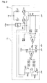
- Fig. 1 shows a current limiting circuit diagram of a brushless DC fan motor according to a first embodiment of the present invention.
- numeral 11 denotes a current limiting circuit of a brushless DC fan motor (circuit) 32.
- circuit a brushless DC fan motor
- the brushless DC fan motor 32 comprises field coils L1 and L2, switching elements respectively connected in series to the field coils L1 and L2, i.e., FETs T1 and T2, and a drive circuit DRV.
- the field coils L1 and L2 are mounted on a stator (not shown) and electrified in an alternately switching manner by the FETs T1 and T2 to form the rotating magnetic field.
- a rotor (not shown) is rotated by making a permanent magnet provided thereon rotated following the above rotating magnetic field.
- the drive circuit DRV gives the ON signal (H level) to gates (control input terminals) G of the FETs T1 and T2 according to the position of rotation of the rotor, and alternately turns ON/turns OFF the FETs T1 and T2.
- the current limiting circuit 11 comprises resistors R0, R2, R3 and R11 to R14, a differential amplifier AMP, a converter COM, a capacitor C2, a PNP transistor Q1, an NPN transistor Q2 and diodes D1 and D2.
- the resistor R0 is a current-detecting resistor which is connected in series to the field coils L1 and L2 to detect the current in the field coils L1 and L2 and detects the current in the coils L1 and L2 by converting the current into the voltage VA produced therebetween.
- the capacitor C2 is used for removing the noise.
- the differential amplifier AMP comprises an operational amplifier, and the voltage VA produced across the current-detecting resistor R0 is applied between a non-inverting input terminal + and an inverting input terminal - via the resistors R1 and R12.
- the non-inverting input terminal + is located on the brushless DC fan motor 32 side, and the inverting input terminal - is located on the ground side.
- the differential amplifier AMP amplifies the voltage VA produced across the current-detecting resistor R0 to allow a large set value of the reference voltage Vf which will be described below.
- the differential amplifier AMP achieves the amplifying operation without being affected by the change in temperature, the change in power source voltage, etc. on the whole since the effects of the change in temperature, the change in power source voltage, etc. on the voltage signals of the non-inverting input terminal + and the inverting input terminal - are canceled by each other.
- the comparator COM comprises an operational amplifier, and the voltage (the control voltage) according to the voltage VA produced across the current-detecting resistor R0, i.e., the output voltage VB of the differential amplifier AMP is applied to the inverting input terminal -, and the reference voltage Vf set by resistance voltage dividers (resistors R2 and R3) is applied to the non-inverting input terminal +, respectively.
- the reference voltage Vf is the voltage corresponding to the allowable maximum value of the preset current, for example, the allowable maximum value If of the excess current when the motor is started or forcibly stopped by the external force or the like.
- the comparator COM compares the control voltage VB from the current-detecting resistor R0 side with the reference voltage Vf when the motor is driven, and outputs the L (Low) level signal for the period in which the control voltage VB exceeds the reference voltage Vf.
- the output signal VC of the comparator COM is on the L level, a transistor Q1 is turned on, a transistor Q2 is accordingly turned on, and thus diodes D1 and D2 are forward-biased to realize the conduction.
- Each gate G of the FETs T1 and T2 is grounded through the diodes D1 and D2 and between the collector-emitter of the transistor Q2.
- the FETs T1 and T2 are turned off irrespective of the state of the control signal from the drive circuit DRV, and the electrification to the field coils L1 and L2 is shut off. This means that the current is limited when the current in the field coils L1 and L2 exceeds the allowable maximum value If of the excess current when the motor is started or forcibly stopped by the external force or the like.
- the OFF state of the FETs T1 and T2 is continued so long as the control voltage VB exceeds the reference voltage Vf, and the current is limited when the motor is started, or forcibly stopped by the external force.
- control voltage VB to the comparator COM is obtained by amplifying the voltage VA produced across the current-detecting resistor R0 by the differential amplifier AMP and can be set to be a large value without limiting the current in the field coils L1 and L2, i.e., without increasing the current-detecting resistor R0.
- the reference voltage Vf can be set to be a large value, and the comparison of high accuracy can be realized in the comparator COM.
- the comparator is less easily affected by various kinds of disturbance factors such as the change in temperature, the change in power source voltage or the noise from the inside and outside a current limiting circuit 31, and the waveform of the output signal VC of the comparator COM is not expressed by the waveform VC' shown in Fig 4, but the waveform VC shown in Fig. 4 can be maintained.
- the ON-OFF frequency of the current when the motor is started, or forcibly stopped by the external force is not decreased, i.e., the current can be maintained to be not less than I kHz, and any harsh grating noise is not generated when the motor is started, or forcibly stopped by the external force.
- Fig. 2 is a current limiting circuit diagram of the brushless DC fan motor according to a second embodiment of the present invention.
- numeral 21 denotes a current limiting circuit of the brushless DC fan motor (circuit) 32.
- the current limiting circuit 21 in the two-phase motor 32 is also shown here similar to that in Fig. 1.
- the second embodiment is similar to the above first embodiment except that the voltage signal applied to the inverting input terminal - of the comparator COM comprising the operational amplifier is reverse to the voltage signal applied to the non-inverting input terminal +, and the circuit configuration between the output terminal of the comparator COM and the gates (control input terminals) G of the FETs T1 and T2 is different.
- the reference voltage Vf set by resistance voltage dividers (resistors R2 and R3) and the voltage (the control voltage) VB according to the voltage VA produced across the current-detecting resistor R0 are applied to the inverting input terminal - of the comparator COM and the non-inverting input terminal +, respectively.
- the configuration between the output terminal of the comparator COM and the gates (control input terminals) G of the FETs T1 and T2 comprises diodes D21 and D22, resistors R21 to R24, and switching elements, i.e., transistors Q21 and Q22.
- an anode and a cathode are connected to the output terminal of the comparator COM and a base of the NPN transistor Q21 via the resistor R21, respectively.
- a collector is grounded via the resistor R22, and connected to the gate G of the FET T1, and an emitter is grounded.
- an anode and a cathode are connected to the output terminal of the comparator COM and a base of the NPN transistor Q22 via the resistor R23, respectively.
- a collector is grounded via the resistor R24, and connected to the gate G of the FET T2, and an emitter is grounded.
- control voltage VB to the comparator COM is obtained by amplifying the voltage VA produced across the current-detecting resistor R0 by the differential amplifier AMP.
- the comparator COM compares the control voltage VB from the current-detecting resistor R0 side with the reference voltage Vf when driving the motor, and outputs the H (High) level signal for the period in which the control voltage VB exceeds the reference voltage Vf.
- the diodes D21 and D22 are forward-biased to realize the conduction, and the bases of the transistors Q21 and Q22 are set to be on the H level via the resistors R21 and R22, respectively.
- the ON signal (the control signal on the H level) is given from the drive circuit DRV to each gate G of the FETs T1 and T2
- the gate G of the FET T1 or T2 with the ON signal (on the H level) given thereto is grounded via the collector-emitter of the transistor Q21 or Q22.
- the gate G of the FET T1 or T2 connected in series to the field coil L1 or L2 on the supply side of the current to generate the control voltage VB (the voltage VA) exceeding the reference voltage Vf is grounded.
- the FETs T1 and T2 are turned off irrespective of the state of the control signal from the drive circuit DRV for the period in which the control voltage VB exceeds the reference voltage Vf and shut off the field coils L1 and L2 to be electrified.
- the current is limited when the current in the field coils L1 and L2 exceeds the allowable maximum value If of the excess current when the motor is started, or forcibly stopped by the external force.
- the OFF state of the FETs T1 and T2 is continued so long as the control voltage VB exceeds the reference voltage Vf, and the current is limited when the motor is started, or forcibly stopped by the external force.
- the output signal VC of the comparator COM is on the L (Low) level, the diodes D21 and D22 are reverse-biased to realize no conduction, and the bases of the transistors Q21 and Q22 are set on the L level, respectively.
- each gate G of the FETs T1 and T2 is released from the grounded state, and the FETs T1 and T2 are controlled by the signal from the drive circuit DRV. In other words, the rotation is returned to be normal.
- control voltage VB to the comparator COM is obtained by amplifying the voltage VA produced across the current-detecting resistor R0, and can be set to be a large value without increasing the current-detecting resistor R0.
- the reference voltage Vf can be set to be a large value, and the comparison of high accuracy can be realized in the comparator COM, and thus, any harsh grating noise is not generated when the motor is started, or forcibly stopped by the external force similar to the first embodiment.
- the second embodiment includes the transistors Q21 and Q22 which ground the gate G of the FET T1 or T2 connected in series to the field coil L1 or L2 on the supply side of the current to produce the control voltage VB exceeding the reference voltage Vf for the period in which the control voltage VB exceeds the reference voltage Vf, and shut off the electrification to the field coil L1 or L2.
- the transistors Q21 and Q22 are individually, i.e., alternately turned ON/turned OFF to the FETs T1 and T2.
- the factors of generating the harsh grating noise can be reduced more than the configuration of a conventional technology or in the above first embodiment in which both the transistors Q 1 and Q2 are turned on commonly to the FETs T1 and T2, i.e., continuously so long as the control voltage VB is not less than the reference voltage Vf. in addition, all current limiting functions are not lost when one switch element (the transistor Q21 or Q22, the transistor Q1 or Q2) is failed.
- the FET, the transistor and the operational amplifier are employed for the switching element, the switch element, and the comparator and the differential amplifier, respectively; but the embodiments are not limited to this example.
- the brushless DC fan motor is not limited to the two-phase one.
- the accuracy in comparison in the comparator is improved between the control voltage according to the current in the field coil and the reference voltage according to the current to be limited when the motor is started, or forcibly stopped by the external force by interposing the differential amplifier between the current-detecting resistor of the field coil and the comparator.
- the ON-OFF frequency of the current is less than 1 kHz when limiting the current by shutting off the field coil to be electrified for the period in which the control voltage exceeds the reference voltage by the output signal of the comparator, and the harsh grating noise can be prevented.
- the switch element is provided corresponding to the switching element connected in series to the field coil, and the control input terminal of the switching element connected in series to the field coil on the supply side of the current to produce the control voltage exceeding the reference voltage for the period in which the control voltage exceeds the reference voltage is grounded.
- the switch element is turned ON/turned OFF individually to a plurality of switching elements, and the factors of generating the harsh grating noise in this configuration can be reduced more than the configuration in which the switch element common to a plurality of switching elements is turned ON/turned OFF, and the harsh grating noise can be further eliminated thereby.
Landscapes
- Engineering & Computer Science (AREA)
- Power Engineering (AREA)
- Control Of Motors That Do Not Use Commutators (AREA)
- Continuous-Control Power Sources That Use Transistors (AREA)
Abstract
Description
Claims (2)
- A current limiting circuit to limit the current running in field coils of a brushless DC fan motor comprising a stator having a plurality of the field coils and a rotor having a permanent magnet in which the rotor is rotated by alternately switching the current running in the field coils and rotating the permanent magnet following the rotating magnetic field formed by the field coils by shutting off the field coils to be electrified for a period in which the control voltage exceeds the reference voltage by the output signal of a comparator which compares the control voltage as the voltage according to the voltage produced across a current-detecting resistor interposed in electrified passages of the field coils with the preset reference voltage comprising:a differential amplifier which is interposed between the current-detecting resistor and the comparator, amplifies the voltage produced across the current-detecting resistor and applies the voltage to the comparator as the control voltage.
- A current limiting circuit to limit the current in field coils of a brushless DC fan motor comprising a stator having a plurality of the field coils with each switching element connected in series thereto and a rotor having a permanent magnet in which the rotor is rotated by alternately switching the current in the field coils by turning ON/turning OFF the switching elements and rotating the permanent magnet following the rotating magnetic field formed by the field coils by shutting off the field coils to be electrified for a period in which the control voltage exceeds the reference voltage by the output signal of a comparator which compares the control voltage as the voltage according to the voltage produced across a current-detecting resistor interposed in electrified passages of the field coils with the preset reference voltage comprising:a differential amplifier which is interposed between the current-detecting resistor and the comparator, amplifies the voltage produced across the current-detecting resistor and applies the voltage to the comparator as the control voltage; andswitch elements which are provided corresponding to each of the switching elements, receive the output signal of the comparator and shut off the electrification to the field coils with a control input terminal of the switching elements connected in series to the field coils on the supply side of the current to produce the control voltage exceeding the reference voltage for a period in which the control voltage exceeds the reference voltage.
Applications Claiming Priority (2)
| Application Number | Priority Date | Filing Date | Title |
|---|---|---|---|
| JP2001191384A JP2003009574A (en) | 2001-06-25 | 2001-06-25 | Current-limiter circuit for brushless dc fan motor |
| JP2001191384 | 2001-06-25 |
Publications (3)
| Publication Number | Publication Date |
|---|---|
| EP1271758A2 true EP1271758A2 (en) | 2003-01-02 |
| EP1271758A3 EP1271758A3 (en) | 2003-12-10 |
| EP1271758B1 EP1271758B1 (en) | 2007-05-02 |
Family
ID=19030017
Family Applications (1)
| Application Number | Title | Priority Date | Filing Date |
|---|---|---|---|
| EP02405533A Expired - Lifetime EP1271758B1 (en) | 2001-06-25 | 2002-06-25 | Current limiting circuit for a brushless DC motor |
Country Status (5)
| Country | Link |
|---|---|
| US (1) | US6674257B2 (en) |
| EP (1) | EP1271758B1 (en) |
| JP (1) | JP2003009574A (en) |
| CN (1) | CN100466454C (en) |
| DE (1) | DE60219851T2 (en) |
Cited By (2)
| Publication number | Priority date | Publication date | Assignee | Title |
|---|---|---|---|---|
| WO2008064735A1 (en) * | 2006-11-30 | 2008-06-05 | Ellenberger & Poensgen Gmbh | Ceiling fan with illumination and control for limiting the power |
| EP2151917A3 (en) * | 2008-08-05 | 2015-08-05 | BITRON S.p.A. | Method for controlling a two-phase d.c. brushless motor without a position sensor |
Families Citing this family (19)
| Publication number | Priority date | Publication date | Assignee | Title |
|---|---|---|---|---|
| CN100377491C (en) * | 2004-10-30 | 2008-03-26 | 鸿富锦精密工业(深圳)有限公司 | DC fan self-starting circuit |
| US20080116753A1 (en) * | 2006-11-17 | 2008-05-22 | Vito James Carlucci | Appliances with brushless motors |
| CN101222196A (en) * | 2007-01-08 | 2008-07-16 | 鸿富锦精密工业(深圳)有限公司 | fan drive circuit |
| CN101334673A (en) * | 2007-06-29 | 2008-12-31 | 鸿富锦精密工业(深圳)有限公司 | Computer fan control circuit and control method |
| CN101576763B (en) * | 2008-05-08 | 2012-09-19 | 鸿富锦精密工业(深圳)有限公司 | Fan control circuit |
| CA2756303C (en) * | 2009-05-04 | 2018-08-14 | Delta T Corporation | Ceiling fan with variable blade pitch and variable speed control |
| US8337618B2 (en) * | 2009-10-26 | 2012-12-25 | Samsung Display Co., Ltd. | Silicon crystallization system and silicon crystallization method using laser |
| WO2011099262A1 (en) * | 2010-02-10 | 2011-08-18 | パナソニック株式会社 | Brushless motor drive device, brushless motor, and air conditioner |
| CN102400933A (en) * | 2010-09-17 | 2012-04-04 | 鸿富锦精密工业(深圳)有限公司 | Fan drive circuit |
| TW201216831A (en) * | 2010-10-14 | 2012-04-16 | Hon Hai Prec Ind Co Ltd | Control system and method for fan |
| CN102562635A (en) * | 2010-12-24 | 2012-07-11 | 鸿富锦精密工业(深圳)有限公司 | Fan rotational speed control circuit |
| US10428824B2 (en) | 2012-06-25 | 2019-10-01 | Dell Products L.P. | Systems and methods for speed control of an air mover |
| JP6067324B2 (en) * | 2012-10-25 | 2017-01-25 | ローム株式会社 | Motor drive device, electronic equipment, vehicle |
| CN103078294B (en) * | 2013-01-10 | 2016-11-23 | 北京曙光航空电气有限责任公司 | Brushless direct current motor controller current foldback circuit |
| JP2015154658A (en) * | 2014-02-18 | 2015-08-24 | セイコーエプソン株式会社 | Circuit device and electronic device |
| JP6892303B2 (en) * | 2017-03-30 | 2021-06-23 | ルネサスエレクトロニクス株式会社 | Motor drives, methods, and programs |
| CN109245620B (en) * | 2018-11-02 | 2025-06-17 | 林齐新 | A computer fan drive system capable of limiting starting current |
| TWI677181B (en) | 2018-11-08 | 2019-11-11 | 財團法人工業技術研究院 | Driving device for multi-axis common-mode voice coil motor |
| US11169218B2 (en) * | 2018-12-21 | 2021-11-09 | Analog Devices, Inc. | Current monitor with fault detection |
Family Cites Families (12)
| Publication number | Priority date | Publication date | Assignee | Title |
|---|---|---|---|---|
| JPS5235083B2 (en) * | 1972-02-26 | 1977-09-07 | ||
| US4710686A (en) * | 1986-08-04 | 1987-12-01 | Guzik Technical Enterprises | Method and apparatus for control of current in a motor winding |
| JPS63181024A (en) * | 1987-01-23 | 1988-07-26 | Toshiba Corp | Reader/writer for portable storage medium |
| US5038247A (en) * | 1989-04-17 | 1991-08-06 | Delco Electronics Corporation | Method and apparatus for inductive load control with current simulation |
| JP2718458B2 (en) * | 1990-02-14 | 1998-02-25 | アスモ株式会社 | Overcurrent protection circuit for brushless motor |
| KR960009359U (en) * | 1994-08-10 | 1996-03-16 | Current Limiting Circuit of Voltage / Frequency (V / F) Inverter | |
| US5721474A (en) * | 1995-08-11 | 1998-02-24 | Samsung Electronics Co., Ltd. | Method and apparatus for preventing excessive current flow in a motor |
| CN2247392Y (en) * | 1995-11-24 | 1997-02-12 | 陈民勇 | Adjustable current-limiting voltage-limiting protector for voltage regulator |
| DE19807253C1 (en) * | 1998-02-20 | 1999-09-02 | Siemens Nixdorf Inf Syst | Method and circuit arrangement for speed detection of electronically commutated fans |
| JP3408447B2 (en) * | 1998-03-13 | 2003-05-19 | インターナショナル・レクチファイヤー・コーポレーション | Linear current detection circuit for motor controller |
| US6285146B1 (en) * | 1998-08-07 | 2001-09-04 | Nidec America Corporation | Apparatus and method of regulating the speed of a brushless DC motor |
| KR20000019528A (en) * | 1998-09-12 | 2000-04-15 | 윤종용 | Apparatus and method for controlling current limiter of motor |
-
2001
- 2001-06-25 JP JP2001191384A patent/JP2003009574A/en active Pending
-
2002
- 2002-06-25 CN CNB021437459A patent/CN100466454C/en not_active Expired - Fee Related
- 2002-06-25 US US10/178,509 patent/US6674257B2/en not_active Expired - Lifetime
- 2002-06-25 DE DE60219851T patent/DE60219851T2/en not_active Expired - Lifetime
- 2002-06-25 EP EP02405533A patent/EP1271758B1/en not_active Expired - Lifetime
Cited By (2)
| Publication number | Priority date | Publication date | Assignee | Title |
|---|---|---|---|---|
| WO2008064735A1 (en) * | 2006-11-30 | 2008-06-05 | Ellenberger & Poensgen Gmbh | Ceiling fan with illumination and control for limiting the power |
| EP2151917A3 (en) * | 2008-08-05 | 2015-08-05 | BITRON S.p.A. | Method for controlling a two-phase d.c. brushless motor without a position sensor |
Also Published As
| Publication number | Publication date |
|---|---|
| CN100466454C (en) | 2009-03-04 |
| DE60219851D1 (en) | 2007-06-14 |
| US6674257B2 (en) | 2004-01-06 |
| EP1271758B1 (en) | 2007-05-02 |
| JP2003009574A (en) | 2003-01-10 |
| CN1407710A (en) | 2003-04-02 |
| US20030001531A1 (en) | 2003-01-02 |
| DE60219851T2 (en) | 2007-09-06 |
| EP1271758A3 (en) | 2003-12-10 |
Similar Documents
| Publication | Publication Date | Title |
|---|---|---|
| US6674257B2 (en) | Current limiting circuit of brushless DC fan motor | |
| US6879120B2 (en) | Speed control circuit of brushless DC fan motor | |
| US7960929B2 (en) | Motor driving device and motor unit | |
| JP3209547B2 (en) | Linear variable cooling DC fan control circuit | |
| US20070152612A1 (en) | Motor controller | |
| US20030091441A1 (en) | Fan control system using a microcontroller | |
| US6815916B2 (en) | Speed-control drive circuit for a D.C. brushless fan motor | |
| JP2920754B2 (en) | Drive device for brushless DC motor | |
| JP2003219609A (en) | Pin-sharing controller for dc motor | |
| US6909252B2 (en) | Pre-drive circuit for brushless DC single-phase motor | |
| US7053573B2 (en) | Motor drive apparatus, integrated circuit, and motor drive method | |
| US7348744B2 (en) | Brushless DC motor drive apparatus | |
| KR20110133438A (en) | Drive device and driving method of blower | |
| US6297603B1 (en) | Circuit and method to avoid high current spikes in stator windings | |
| JP3293266B2 (en) | Drive circuit for brushless motor | |
| US8330401B2 (en) | Circuit unit for driving an electronically commutated fan motor | |
| US6922038B2 (en) | Speed control circuit for a dc brushless motor | |
| JP2749514B2 (en) | Driving device for DC brushless motor and DC brushless motor | |
| JP4079702B2 (en) | Motor drive control circuit and motor drive device | |
| US9344017B2 (en) | Driving circuit and driving method thereof | |
| US6806598B1 (en) | Double-phase half-wave brushless DC motor having two sensor/drive members | |
| JP2590646Y2 (en) | Brushless motor | |
| KR100231028B1 (en) | The revolving velocity control apparatus of brushless direct motor | |
| JPH08223965A (en) | Drive control circuit for motor | |
| KR20000077001A (en) | Drive control apparatus of brushless motor |
Legal Events
| Date | Code | Title | Description |
|---|---|---|---|
| PUAI | Public reference made under article 153(3) epc to a published international application that has entered the european phase |
Free format text: ORIGINAL CODE: 0009012 |
|
| AK | Designated contracting states |
Kind code of ref document: A2 Designated state(s): AT BE CH CY DE DK ES FI FR GB GR IE IT LI LU MC NL PT SE TR |
|
| AX | Request for extension of the european patent |
Free format text: AL;LT;LV;MK;RO;SI |
|
| PUAL | Search report despatched |
Free format text: ORIGINAL CODE: 0009013 |
|
| AK | Designated contracting states |
Kind code of ref document: A3 Designated state(s): AT BE CH CY DE DK ES FI FR GB GR IE IT LI LU MC NL PT SE TR |
|
| AX | Request for extension of the european patent |
Extension state: AL LT LV MK RO SI |
|
| RIC1 | Information provided on ipc code assigned before grant |
Ipc: 7H 02P 6/20 B Ipc: 7H 02P 1/46 B Ipc: 7H 02P 6/00 A |
|
| 17P | Request for examination filed |
Effective date: 20040605 |
|
| 17Q | First examination report despatched |
Effective date: 20040720 |
|
| AKX | Designation fees paid |
Designated state(s): DE GB |
|
| GRAP | Despatch of communication of intention to grant a patent |
Free format text: ORIGINAL CODE: EPIDOSNIGR1 |
|
| GRAS | Grant fee paid |
Free format text: ORIGINAL CODE: EPIDOSNIGR3 |
|
| GRAA | (expected) grant |
Free format text: ORIGINAL CODE: 0009210 |
|
| AK | Designated contracting states |
Kind code of ref document: B1 Designated state(s): DE GB |
|
| REG | Reference to a national code |
Ref country code: GB Ref legal event code: FG4D |
|
| REF | Corresponds to: |
Ref document number: 60219851 Country of ref document: DE Date of ref document: 20070614 Kind code of ref document: P |
|
| PLBE | No opposition filed within time limit |
Free format text: ORIGINAL CODE: 0009261 |
|
| STAA | Information on the status of an ep patent application or granted ep patent |
Free format text: STATUS: NO OPPOSITION FILED WITHIN TIME LIMIT |
|
| 26N | No opposition filed |
Effective date: 20080205 |
|
| PGFP | Annual fee paid to national office [announced via postgrant information from national office to epo] |
Ref country code: GB Payment date: 20090624 Year of fee payment: 8 |
|
| GBPC | Gb: european patent ceased through non-payment of renewal fee |
Effective date: 20100625 |
|
| PG25 | Lapsed in a contracting state [announced via postgrant information from national office to epo] |
Ref country code: GB Free format text: LAPSE BECAUSE OF NON-PAYMENT OF DUE FEES Effective date: 20100625 |
|
| PGFP | Annual fee paid to national office [announced via postgrant information from national office to epo] |
Ref country code: DE Payment date: 20130619 Year of fee payment: 12 |
|
| REG | Reference to a national code |
Ref country code: DE Ref legal event code: R119 Ref document number: 60219851 Country of ref document: DE |
|
| REG | Reference to a national code |
Ref country code: DE Ref legal event code: R119 Ref document number: 60219851 Country of ref document: DE Effective date: 20150101 |
|
| PG25 | Lapsed in a contracting state [announced via postgrant information from national office to epo] |
Ref country code: DE Free format text: LAPSE BECAUSE OF NON-PAYMENT OF DUE FEES Effective date: 20150101 |