Technical Field
The present invention relates to a mobile terminal, and more
specifically, to a mobile terminal as represented by a mobile phone.
Background Art
The use of mobile phones has been spreading rapidly these days.
Under such circumstances, the development regarding prevention of
transmission gain degradation is proceeding. Fig. 27 is a perspective view
of a conventional mobile phone. Referring to Fig. 27, a housing 402 of a
mobile wireless radio as a mobile phone is divided into a first unit 402a
having a receiver unit, and a second unit 402b without a receiver unit. The
second unit 402b is foldably connected to the lower portion of the first unit
402a by a folding unit 402c. An aerial 401 as an antenna is formed to
project upwardly toward the first unit 402a from an upper end surface 423 of
the second unit 402b of the housing 402 of the mobile radio.
In the above mentioned conventional mobile phone, however, the
following problems are involved.
First, since the antenna is extending from the housing and exposed,
it tends to contact with user's fingers. In such a case, a problem arises that
the antenna gain degrades under the effect of fingers.
Further, though there is the first unit 402a between a user's head
and the aerial 401, it does not act as a shielding plate for electromagnetic
waves due to the wide distance between the first unit 402a and the aerial
401. As a result, the aerial is affected by the user's head, and thus the
antenna gain is diminished.
In addition, when the mobile phone is placed on a conductive
material such as a metal board, a problem arises that antenna gain of the
aerial 401 is degraded under the effect of the metal board, which in turn
degrades speech quality.
Therefore, an object of the present invention is to solve the problems
described above, and to provide a mobile terminal that can alleviate
degradation of antenna gain.
Disclosure of the Invention
A mobile terminal according to the present invention includes a first
housing having one end and the other end, a second housing having one end
and the other end, with that one end being pivotally mounted to the first
housing, and a first antenna element accommodated in one end of the first
housing. The other end of the second housing pivots toward or away from
the other end of the first housing. Upon use, the other end of the second
housing is distanced from the other end of the first housing and held in close
proximity to a user's head Upon use, the first housing is disposed relative
to the second housing so that the second housing intervenes between the
first antenna element and the user's head.
In thus formed mobile terminal, the first antenna element is
accommodated in the first housing. Thus the first antenna element will not
be affected by the contact with fingers, and therefore degradation of the
antenna gain is prevented. Further, even when the mobile terminal is
placed on a metal board, the antenna gain will not degrade since the first
housing intervenes between the first antenna element and the metal board.
Additionally, since the second housing intervenes between the first antenna
element and the user's head upon use, and the distance between the first
antenna element and the second housing is shortened, the second housing
shields the electromagnetic wave transmitted to/received by the first
antenna element. Therefore, the antenna element will not be affected by
the user's head and thus degradation of the antenna gain can be prevented.
Preferably, the first antenna element includes at least one type of
antenna selected from the group consisting of a monopole antenna, a dipole
antenna, a plate antenna, an inverted F type antenna, and a loop antenna.
Preferably, the first antenna element is accommodated between a
portion of the first housing to which one end of the second housing is
connected, and one end of the first housing.
Preferably, the first housing includes a first surface facing to the
user's head and a second surface opposing to the first surface, and the first
antenna element is accommodated close to the first surface. Thus, since the
first antenna element is accommodated close to the position distanced from
the second surface which is to contact with fingers, that the first antenna
element is protected from the effect of the user. As a result, further stable
antenna gain can be attained.
Preferably, a conductive plate with constant potential is
accommodated close to the second surface. Thus, the first antenna element
is less affected by fingers in contact with the second surface.
Preferably, the mobile terminal further includes a second antenna
element at the other end of the second housing.
Preferably, the first housing includes either one of a liquid crystal
display unit indicating text information or an operation unit to be pressed by
fingers for operation. The second housing includes the other one of the
liquid crystal display unit or the operation unit.
Preferably, the operation unit includes a substrate extending from
one end to the other end within the first housing, and the first antenna
element is provided on the substrate.
Preferably, the second housing is conductive. Thus, the second
housing has an effect to shield electromagnetic wave, thus the antenna is
less likely affected by the user's head, and degradation of antenna gain is
prevented.
The foregoing and other objects, features, aspects and advantages of
the present invention will become more apparent from the following detailed
description of the present invention when taken in conjunction with the
accompanying drawings.
Brief Description of the Drawings
Fig. 1 is a schematic side view of a mobile phone according to a first
embodiment of the present invention.
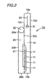
Fig. 2 shows the mobile phone illustrated in Fig. 1 in a compact form.
Fig. 3 is a schematic side view of a mobile phone according to a
second embodiment of the present invention.
Fig. 4 is a schematic side view of a mobile phone according to a third
embodiment of the present invention.
Fig. 5 is a schematic side view of a mobile phone according to a
fourth embodiment of the present invention.
Fig. 6 is a schematic side view of a mobile phone according to a fifth
embodiment of the present invention.
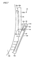
Fig. 7 is a schematic side view of a mobile phone according to a sixth
embodiment of the present invention.
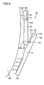
Fig. 8 is a schematic side view of a mobile phone according to a
seventh embodiment of the present invention.
Fig. 9 is a schematic side view of a mobile phone according to an
eighth embodiment of the present invention.
Fig. 10 is a schematic side view of a mobile phone according to a
ninth embodiment of the present invention.
Fig. 11 is a schematic side view of a mobile phone according to a
tenth embodiment of the present invention.
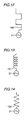
Fig. 12 is a schematic view of antennas used in a mobile phone of the
present invention.
Fig. 13 is a schematic view of antennas used in a mobile phone of the
present invention.
Fig. 14 is a schematic view of antennas used in a mobile phone of the
present invention.
Fig. 15 is a schematic view of antennas used in a mobile phone of the
present invention.
Fig. 16 is a schematic view of antennas used in a mobile phone of the
present invention.
Fig. 17 is a schematic view of antennas used in a mobile phone of the
present invention.
Fig. 18 is a schematic view of antennas used in a mobile phone of the
present invention.
Fig. 19 shows relation between a mobile phone and coordinate axes.
Fig. 20 shows relation between a mobile phone and coordinate axes.
Fig. 21 shows a process of measuring a radiation pattern on x-z
plane.
Fig. 22 shows a process of measuring a radiation pattern on x-z
plane.
Fig. 23 shows a process of measuring a radiation pattern on x-z
plane.
Fig. 24 is a graph showing antenna gain with a mobile phone
according to the present invention.
Fig. 25 is a graph showing antenna gain with an index finger placed
on an antenna element.
Fig. 26 is a graph showing antenna gain with a conventional mobile
phone.
Fig. 27 is a perspective view showing a conventional mobile phone.
Best Modes for Carrying Out the Invention
(First Embodiment)
Fig. 1 is a side view of a mobile phone according to a first
embodiment of the present invention. Referring to Fig. 1, the mobile phone
1a as a mobile terminal according to the present invention includes a lower
housing 10 as a first housing having one end 10a and the other end 10b, an
upper housing 20 as a second housing having one end 20a pivotally
connected to the lower housing 10, and a monopole antenna 30 as a first
antenna element accommodated close to one end 10a of the lower housing 10.
The other end of the upper housing 20 pivots toward and away from the
other end 10b of the lower housing 10. The mobile phone 1a is used in close
proximity to a user's head with the other end 20b of the upper housing 20
being distanced from the other end 10b of the lower housing 10. Upon use,
the lower housing 10 is disposed relative to the upper housing 20 so that the
upper housing 20 intervenes between the monopole antenna 30 and the
user's head 100.
The mobile phone 1a includes the lower housing 10 and the upper
housing 20 connected to the lower housing 10. In the one end 10a of the
lower housing 10, the monopole antenna 30 is accommodated. The
monopole antenna 30 is accommodated between a portion of the lower
housing 10 to which the upper housing 20 is connected and one end 10a of
the lower housing 10. The lower housing 10 is made with plastics, and the
monopole antenna 30 is accommodated within the space thereof. A feed
point 31 is provided at one end of the monopole antenna 30. The lower
housing 10 includes a first surface 10c facing to the user's head 100, and a
second surface 10d opposing thereto. The monopole antenna 30 is provided
at the middle point between the first surface 10c and the second surface 10d.
The first surface 10c is provided with an axis 32. A monopole
antenna 30 is provided between the portion to which the axis 32 is mounted
and the one end 10a. The other end 10b of the lower housing 10 is provided
with a plurality of push buttons 11 as an operation unit to be pressed with
fingers for operation. Manual pressing of the push buttons 11 allows input
of information such as telephone numbers.
One end 20a of the upper housing 20 is pivotally connected to the
lower housing 10 via the axis 32. The upper housing 20 extends from one
end 20a to the other end 20b. As materials for structuring the upper
housing 20, not only insulating material such as plastics, but also
conductive materials with high performance of shielding electromagnetic
waves such as magnesium can be employed. It is also possible to plate the
surface of the plastics with highly conductive materials. The first surface
20c of the upper housing 20 is provided with a liquid crystal display device
21 as a liquid crystal display unit for displaying text information. Text
information will appear on the liquid crystal display device to be viewed by
the user. The second surface 20d of the upper housing 20 is disposed
opposite to the first surface 20c and upon use as illustrated in Fig. 1 it will
face to the lower housing 10. Both of the first surface 10c of the lower
housing 10 and the first surface 20c of the upper housing 20 are in close
proximity to the user's head 100.
Fig. 2 illustrates the mobile phone of Fig. 1 in a compact form for
easier accommodation. Referring to Fig. 2, when the mobile phone 1a is to
be made compact, the upper housing 20 pivots toward the lower housing 20
so that the first surface 20c of the upper housing 20 and the first surface 10c
of the lower housing 10 face to each other. Thus, by flipping the upper
housing 20, the overall size of mobile phone can be made compact for easier
accommodation.
In thus formed mobile phone 1a, the monopole antenna 30 is
accommodated in the lower housing 10. Accordingly, since the monopole
antenna 30 will not contact with fingers, the degradation of antenna gain
can be prevented and stable antenna gain can be obtained.
Since the monopole antenna 30 is accommodated in the lower
housing 10, even when the mobile phone 1a is dropped, the monopole
antenna 30 will not be damaged and thus mechanical strength can also be
attained.
Further, when the mobile phone 1a is placed on a metal board, since
the second surface 10d of the lower housing 10 intervenes between the
monopole antenna 30 and the metal board, the antenna characteristics can
be prevented from degradation and becomes stable. As a result, speech
quality will not be degraded.
Additionally, since the distance between the monopole antenna 30
and the upper housing 20 is short, the upper housing 20 will shield
electromagnetic waves. As a result, the monopole antenna 30 can be
protected from the effect of the user's head 100. Thus, degradation of the
antenna gain can be prevented.
(Second Embodiment)
Fig. 3 is a schematic side view of a mobile phone according to a
second embodiment of the present invention. Referring to Fig. 3, the
mobile phone 1b according to the second embodiment of the present
invention is different from the mobile phone 1a according to the first
embodiment in that monopole antenna 30 is provided near the first surface
10c in the lower housing 10.
Thus structured mobile phone 1b primarily has the same effect as
the mobile phone 1a according to the first embodiment. Further, since the
monopole antenna 30 is disposed remotely from the second surface 10d of
the lower housing 10 to which fingers may contact, degradation of antenna
gain can further be alleviated. Additionally, with a thin type of lower
housing 10, degradation of antenna gain due to the effect of fingers can be
prevented as well.
(Third Embodiment)
Fig. 4 is a schematic side view of a mobile phone according to a third
embodiment of the present invention. Referring to Fig. 4, the mobile phone
1c according to the third embodiment of the present invention is different
from the mobile phone 1a according to the first embodiment in that
monopole antenna 30 is provided at one end 10a of the lower housing 10, i.e.,
at the top surface. The monopole antenna 30 extends approximately
orthogonal to the direction to which the lower housing 10 extends.
Thus structured mobile phone 1c also has the same effect as the
mobile phone 1a according to the first embodiment. Further, since the
monopole antenna 30 is attached at the top surface of the lower housing 10,
the attachment area of the antenna can be made smaller.
(Fourth Embodiment)
Fig. 5 is a schematic side view of a mobile phone according to a
fourth embodiment of the present invention. Referring to Fig. 5, a mobile
phone 1d according to the fourth embodiment of the present invention is
different from the mobile phone 1a according to the first embodiment in that
the provided monopole antenna 30 is bent. Such monopole antenna 30 is in
the composite form of antennas described in the first to third embodiments.
Thus structured mobile phone 1d also has the same effect as the
mobile phone 1a according to the first embodiment.
(Fifth Embodiment)
Fig. 6 is the schematic side view of a mobile phone according to a
fifth embodiment of the present invention. Referring to Fig. 6, the mobile
phone 1e according to the fifth embodiment of the present invention is
different from the mobile phone 1a according to the first embodiment in that
a metal plate 34 as a ground with constant potential is provided between the
monopole antenna 30 and the second surface 10d. The metal plate 34
prevents the monopole antenna 30 from affected by user's finger 80.
Thus structured mobile phone 1d also has the same effect as the
mobile phone 1a according to the first embodiment. Further, by placing the
metal plate 34 to be the ground in the portion possibly contacted by fingers,
the effect upon contact can further be reduced.
(Sixth Embodiment)
Fig. 7 is the schematic side view of a mobile phone according to a
sixth embodiment of the present invention. Referring to Fig. 7, the mobile
phone if according to the sixth embodiment of the present invention is
different from the mobile phone 1a according to the first embodiment in that
a vibrator 35 is provided near the monopole antenna 30, which is connected
to a substrate 37 via a coil 36. The vibrator 35 can be replaced with other
components. The coil 36 is provided between the vibrator 35 and the
substrate37, thus vibrator is less likely affected by high frequency waves
which is input to/output from the monopole antenna 30.
Thus structured mobile phone if also has the same effect as the
mobile phone 1a according to the first embodiment. Further, by attaching
components such as the vibrator near the antenna, the mobile phone if can
be made compact. Additionally, the vibrator can be enclosed by a material
with high conductivity to oscillate as an antenna element itself.
(Seventh Embodiment)
Fig. 8 is the schematic side view of a mobile phone according to a
seventh embodiment of the present invention. Referring to Fig. 8, the
mobile phone 1g according to the seventh embodiment of the present
invention is different from the mobile phone 1a according to the first
embodiment in that a hole 10h for a strap is provided in the lower housing
10, with the monopole antenna 30 being provided around it. The hole is
shown prismatic, but it may be formed as cylindrical as well.
Thus structured mobile phone 1g also has the same effect as the
mobile phone 1a according to the first embodiment.
(Eighth Embodiment)
Fig. 9 is the schematic side view of a mobile phone according to a
eighth embodiment of the present invention. Referring to Fig. 9, the mobile
phone 1h according to the present invention is different from the mobile
phone 1a according to the first embodiment in that a monopole antenna 50 is
also provided at the other end 20b of the upper housing 20. The monopole
antenna 50 is connected to the feed point 51. The monopole antenna 50 is
not necessarily be accommodated in the upper housing 20, and it may be
projected from the upper housing 20. Further, the monopole antenna 50
can be provided at either side of the first surface 20c or the second surface
20d of the upper housing 20.
Thus structured mobile phone 1h also has the same effect as the
mobile phone 1a according to the first embodiment. Further, whether the
mobile phone 1h is in use or in the folded form, the distance between the
monopole antenna 30 and the monopole antenna 50 are long; in other words,
these antennas are kept separated in either case. As a result, degradation
of the antenna effect can be prevented, alleviating troubles upon
transmission. Further, the monopole antenna 50 may be a monopole
antenna 30 at the same frequency band (e.g., a diversity antenna).
Additionally, it may be an antenna for other systems (Bluetooth or Global
Positioning System, GPS).
(Ninth Embodiment)
Fig. 10 is the schematic side view of a mobile phone according to a
ninth embodiment of the present invention. Referring to Fig. 10, the
mobile phone 1i according to the ninth embodiment of the present invention
is different from the mobile phone 1a according to the first embodiment in
that an operation unit includes an extended substrate 37, and a feed point
31 and a strip antenna 230 are formed thereon.
Thus structured mobile phone 1h also has the same effect as the
mobile phone 1a according to the first embodiment. Further, by extending
the substrate of the operation unit and forming the antenna thereon, the
cost reduction can be contemplated.
(Tenth Embodiment)
Fig. 11 is the schematic side view of a mobile phone according to a
tenth embodiment of the present invention. Referring to Fig. 11, the
mobile phone 1j according to the tenth embodiment of the present invention
is different from the mobile phone 1a according to the first embodiment in
that the monopole antenna 30 is accommodated close to one end 520a of an
upper housing 520. In particular, the mobile phone 1j as a mobile terminal
according to the present invention includes an upper housing 520 as a first
housing having one end 520a and the other end 520b, a lower housing 510 as
a second housing having one end 510a pivotally mounted to the upper
housing 520, and a monopole antenna 30 as a first antenna element
accommodated close to the one end 520a of the upper housing 520. The
other end 510b of the lower housing 510 pivots toward and away from the
other end 520b of the upper housing 520. The mobile phone 1j is used with
the other end 510b of the lower housing 510 being distanced from the other
end 520b of the upper housing 520 and in close proximity to the user's head
100. Upon use, the lower housing 510 is disposed relative to the upper
housing 520 so that the lower housing 510 intervenes between the monopole
antenna 30 and the user's head 100. The upper housing 520 has a first
surface 520c and a second surface 520d, while the lower housing 510 has a
first surface 510c and a second surface 510d.
Thus structured mobile phone 1j also has the same effect as the
mobile phone 1a according to the first embodiment.
(Eleventh Embodiment)
Figs. 12 to 18 illustrate antennas used in the mobile phones
according to the present invention. Referring to Fig. 12, in the mobile
phone according to the present invention, a meanderline antenna 130 as a
monopole antenna may be used in place of monopole antenna 30 shown in
Figs. 1 to 11.
Referring to Fig. 13, in the mobile phone according to the present
invention, a helical antenna 131 as a monopole antenna may be used in
place of monopole antenna 30 shown in Figs. 1 to 11.
Referring to Fig. 14, in the mobile phone according to the present
invention, a zigzag antenna 132 as a monopole antenna may be used in
place of monopole antenna 30 shown in Figs. 1 to 11.
Referring to Fig. 15, in the mobile phone according to the present
invention, a plate antenna 133 such as a patch antenna or a short patch
antenna may be used in place of monopole antenna 30 shown in Figs. 1 to
11.
Referring to Fig. 16, in the mobile phone according to the present
invention, an inverted F type antenna 134 may be used in place of monopole
antenna 30 shown in Figs. 1 to 11.
Referring to Fig. 17, in the mobile phone according to the present
invention, a loop antenna 135 may be used in place of monopole antenna 30
shown in Figs. 1 to 11.
Referring to Fig. 18, in the mobile phone according to the present
invention, a dipole antenna 136 may be used in place of monopole antenna
30 shown in Figs. 1 to 11.
Next, radiation characteristics of the mobile phone according to the
present invention and a conventional mobile phone were compared. Figs.
19 and 20 show relation between the mobile phone and coordinate axes.
Note that Fig. 19 is a rear view of the mobile phone, while Fig. 20 is a side
view thereof. First, a mobile phone 1a according to the present invention
was prepared as shown in Figs. 19 and 20. The mobile phone 1a includes a
lower housing 10 and an upper housing 20. At one end 10a of the lower
housing 10, a monopole antenna 30 in accommodated.
The direction to which the monopole antenna 30 extends is +Z
direction. Further, from left to right direction in Fig. 19 is +Y direction.
The direction from depth toward the plane of Fig. 19 is +X direction.
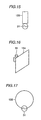
Figs. 21 to 23 illustrate a process of measuring a radiation pattern in
the X-Z plane. First, referring to Fig. 21, the mobile phone 1a shown in
Figs. 19 and 20 was placed on a table 150. Here, the placement was done
such that the +Z direction and +X direction are orthogonal to the vertical
direction indicated by an arrow 140. Thus, +Y direction is approximately
parallel to the perpendicular direction represented by the arrow 140. The
table 150 can be rotated in the direction indicated by an arrow R. A user
was present near the first plane 10c and 20c.
In such a state in which the mobile phone 1a was placed on the table
150, radio wave at the frequency of 940 MHz was radiated from a radio
transceiver unit via the monopole antenna 30 at a prescribed power. At the
same time, the table was rotated in the direction indicated by the arrow R.
Thus, a radio wave as indicated by the arrow 151 was radiated. The field
intensity of the radio wave was measured by a measuring antenna 160, and
the field intensity of vertically polarized wave in the direction indicated by
an arrow V and horizontally polarized wave in the direction indicated by an
arrow H was determined.
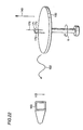
Referring to Fig. 22, a dipole antenna 170 was placed on the table
150. A feed point 171 was provided at the middle portion of the dipole
antenna 170 and connected to a coaxial cable 172. The coaxial cable 172
was connected to the prescribed radio transceiver unit. The dipole antenna
170 extends approximately parallel to the perpendicular direction indicated
by the arrow 140. By turning the table 150 in the direction indicated by the
arrow R, and applying similar power to the dipole antenna 170 as applied to
the mobile phone 1a by the radio transceiver unit illustrated in Fig. 21, radio
wave as indicated by an arrow was radiated from the dipole antenna 170 at
the frequency of 940 MHz. Thus, the radio wave indicated by the arrow
152 was radiated from the dipole antenna 170. The radio wave is a
vertically polarized wave in the direction indicated by an arrow V. The
field intensity of the radio wave was measured by a measuring antenna 160.
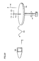
Referring to Fig. 23, the dipole antenna 170 was placed on the table
150. The dipole antenna was placed so that it extends orthogonal to the
vertical direction indicated by the arrow 140. The feed point 171 was
provided at the middle portion of the dipole antenna 170 and connected to
the coaxial cable 172. By turning the table 150 in the direction indicated by
the arrow R, and applying similar power to the dipole antenna 170 as
applied to the mobile phone 1a by the radio transceiver unit illustrated in
Fig. 21, radio wave as indicated by an arrow 153 was radiated from the
dipole antenna 170 at the frequency of 940 MHz. The radio wave was a
horizontally polarized wave in the direction indicated by an arrow H. The
field intensity of the radio wave was measured by the measuring antenna
160.
Based on the data acquired in the process described with reference to
Figs. 21 to 23, an antenna element radiation pattern was determined. The
result is shown in Fig. 24.
In Fig. 24, solid line 301 indicates gain of vertically polarized wave of
radio wave radiated by the monopole antenna 30 shown in Fig. 21 for the
field intensity of the vertically polarized wave radiated by the dipole
antenna 170 in the process shown in Fig. 22. The gain was determined by
the following equation:
(gain) = 20 × log10
(field intensity of the vertically polarized wave from the monopole antenna 30/field intensity of the vertically polarized wave from the dipole antenna 170)
Dotted line 302 indicates gain of horizontally polarized wave of radio
wave radiated by the monopole antenna 30 shown in Fig. 21 for the field
intensity of the horizontally polarized wave radiated by the dipole antenna
170 in the process shown in Fig. 23. The gain was determined by the
following equation:
(gain) = 20 × log10
(field intensity of the horizontally polarized wave from the monopole antenna 30/field intensity of the horizontally polarized wave from the dipole antenna 170)
Meanwhile, one scale shown in Figs. 24 to 26 indicates 10dB. The
mean gain of both vertically and horizontally polarized waves (cross
polarization ratio, XPR=6dB) was determined to be -14.73 dBd.
Additionally, the peak value of the gain was -4.27dBd.
Next, in the process shown in Fig. 21, the lower housing 10 was in
contact with a user's hand at the portion distanced from the monopole
antenna 30 by 2mm. The body of the user was near the first surfaces 10c
and 20c. Under such a condition, the table 150 shown in Fig. 21 was
rotated in the direction of the arrow R and a prescribed power from the radio
transceiver unit was applied to the monopole antenna 30 to radiate radio
wave. Under such a condition, the table was rotated in the direction of the
arrow R and similar power as described in the process with reference to Fig.
21 was applied to the mobile phone 1a from the radio transceiver unit, then
radio wave at the frequency of 940 MHz was radiated. The field intensity
of vertically and horizontally polarized waves of the radio wave were
measured by the measuring antenna 160.
Fig. 25 shows a radiation pattern with a user's hand in contact with
the lower housing 10 placed near the monopole antenna 30. In Fig. 25,
solid line 311 indicates gain of field intensity of vertically polarized wave of
radio wave radiated by the mobile phone 1a with a user's hand in contact
with the lower housing 10 near the monopole antenna 30 for the field
intensity of the vertically polarized wave measured in the process shown in
Fig. 22. The gain was determined by the following equation:
(gain) = 20 × log10
(field intensity of the vertically polarized wave
from the mobile phone 1a with a user's hand in contact with the lower
housing 10 near the monopole antenna 30/field intensity of the vertically
polarized wave from the dipole antenna 170)
Dotted line 312 indicates gain of field intensity of horizontally
polarized wave of radio wave radiated by the mobile phone 1a with a user's
hand in contact with the lower housing 10 near the monopole antenna 30 for
the field intensity of the horizontally polarized wave measured in the
process shown in Fig. 23. The gain was determined by the following
equation:
(gain) = 20 × log10
(field intensity of the horizontally polarized wave
from the mobile phone 1a with a user's hand in contact with the lower
housing 10 near the monopole antenna 30/field intensity of the horizontally
polarized wave from the dipole antenna 170)
From Fig. 25, mean gain of vertically and horizontally polarized
waves (XPR = 6dB) was determined to be a preferable value of -15.33 dBd.
Peak value of the gain was -4.55 dBd.
Accordingly, it can be appreciated that high transmission gain is
acquired in the present invention.
Next, with the conventional mobile wireless radio shown in Fig. 27,
according to the same process as described with reference to Fig. 21, axis Z
and axis X are horizontally directed, while axis Y is placed on the table 150
so as to be parallel to the vertical direction. A person was present opposite
to the aerial 401 of the mobile transceiver. Under such a condition, the
table was rotated in the direction indicated by the arrow R, while radio wave
at the frequency of 940 MHz was radiated via the aerial 401.
Simultaneously, similar power as applied to the monopole antenna 30 by the
radio transceiver unit was applied to the aerial 401. Vertically and
horizontally polarized waves of thus radiated radio waves were measured by
the measuring antenna 160. Fig. 26 shows a radiation pattern for such a
conventional antenna. In Fig. 26, solid line 321 indicates gain of field
intensity of vertically polarized wave of radio wave radiated by the aerial
401 according to the step described with reference to Fig. 21 for the field
intensity of the vertically polarized wave measured in the process shown in
Fig. 22. The gain was determined by the following equation:
(gain) = 20 × log10
(field intensity of the vertically polarized wave
from the aerial 401/field intensity of the vertically polarized wave from the
dipole antenna 170)
Dotted line 322 indicates gain of horizontally polarized wave of radio
wave radiated by the aerial 401 according to the step described with
reference to Fig. 21 for the field intensity of the horizontally polarized wave
measured in the process shown in Fig. 23. The gain was determined by the
following equation:
(gain) = 20 × log10
(field intensity of the horizontally polarized wave
from the aerial 401/field intensity of the horizontally polarized wave from
the dipole antenna 170)
According to Fig. 26, it can be appreciated that gain of vertically and
horizontally polarized waves are both decreased. From Fig. 26, the mean
gain was determined to be -21.35 dBd. Additionally, peak value of gain
was -13.41 dBd.
Industrial Applicability
The mobile terminal according to the present invention can be
utilized in the field of mobile phone.