EP1271597A1 - Method of assembling electron gun electrodes for a cathode ray tube - Google Patents
Method of assembling electron gun electrodes for a cathode ray tube Download PDFInfo
- Publication number
- EP1271597A1 EP1271597A1 EP02291546A EP02291546A EP1271597A1 EP 1271597 A1 EP1271597 A1 EP 1271597A1 EP 02291546 A EP02291546 A EP 02291546A EP 02291546 A EP02291546 A EP 02291546A EP 1271597 A1 EP1271597 A1 EP 1271597A1
- Authority
- EP
- European Patent Office
- Prior art keywords
- electrodes
- electrode
- gun
- jaws
- longitudinal axis
- Prior art date
- Legal status (The legal status is an assumption and is not a legal conclusion. Google has not performed a legal analysis and makes no representation as to the accuracy of the status listed.)
- Withdrawn
Links
- 238000000034 method Methods 0.000 title claims abstract description 19
- 239000011324 bead Substances 0.000 claims abstract description 9
- 210000000078 claw Anatomy 0.000 claims abstract description 7
- 239000011521 glass Substances 0.000 claims abstract description 7
- 238000003780 insertion Methods 0.000 claims abstract description 3
- 230000037431 insertion Effects 0.000 claims abstract description 3
- 238000010894 electron beam technology Methods 0.000 claims description 9
- 230000002093 peripheral effect Effects 0.000 claims description 6
- 235000010627 Phaseolus vulgaris Nutrition 0.000 description 1
- 244000046052 Phaseolus vulgaris Species 0.000 description 1
- 230000000295 complement effect Effects 0.000 description 1
- 239000000470 constituent Substances 0.000 description 1
- 230000014759 maintenance of location Effects 0.000 description 1
- 238000004519 manufacturing process Methods 0.000 description 1
- 238000002844 melting Methods 0.000 description 1
- 230000008018 melting Effects 0.000 description 1
- 239000002184 metal Substances 0.000 description 1
- 239000007787 solid Substances 0.000 description 1
Images


Classifications
-
- H—ELECTRICITY
- H01—ELECTRIC ELEMENTS
- H01J—ELECTRIC DISCHARGE TUBES OR DISCHARGE LAMPS
- H01J9/00—Apparatus or processes specially adapted for the manufacture, installation, removal, maintenance of electric discharge tubes, discharge lamps, or parts thereof; Recovery of material from discharge tubes or lamps
- H01J9/02—Manufacture of electrodes or electrode systems
- H01J9/18—Assembling together the component parts of electrode systems
Definitions
- the subject of the invention is a method of assembling the electrodes of an electron gun for a cathode-ray tube and, more particularly, electrode shapes which allow the implementation of the process.
- the invention is particularly adapted to electron guns for cathode-ray tubes with improved resolution.
- An electron gun takes the form of a succession of electrodes drilled with one or more openings for the passage of the electron beans intended to form an image on the screen of the tube in which the gun is inserted.
- these electrodes On their peripheral surface, these electrodes generally possess metal claws which will be inserted, hot, into glass beads intended to keep the stack of electrodes constituting the gun in place.
- the openings located on two facing electrodes constitute electron lenses intended to act on the trajectory or the shape of the electron beams passing through them.
- the relative positioning of the openings of the electrodes is therefore extremely critical and must be performed with great accuracy.
- the openings of the various electrodes have long been circular and concentric, so that the gun needed to be assembled by stacking the electrodes one above another, cylindrical rods passing through the openings automatically positioning these openings with respect to one another.
- the invention is a method of assembly which is a convenient and efficient.
- the method does not utilize the openings of the electrode themselves as the reference positions, but rather relies on the shape of the periphery of the electrodes for alignment.
- the method of assembling an electron gun for a cathode-ray tube is characterized in that it comprises the following steps:
- the tool for positioning electron gun electrodes for implementing the invention is characterized in that, in the plane perpendicular to the longitudinal axis of the gun, the jaws have a profile intended to cooperate with the shape of the comers of the electrodes in such a way that upon closure of the jaws, the electrodes are brought to their nominal position in the plane perpendicular to the longitudinal axis.
- Figure 1 illustrates a mode of assembly according to the prior art.
- Figures 2A and 2B illustrate an embodiment of an electrode and of an assembly tool allowing assembly according to the invention.
- FIGS. 3 and 4 illustrate a mode of carrying out the invention.
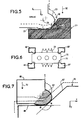
- Figure 5 illustrates a second mode of carrying out the invention.
- FIGS. 6 and 7 show the manner in which the second mode of assembly according to the invention is implemented.
- an electron gun generally consists of a stack of electrodes arranged in succession along a longitudinal axis Z, coinciding with the longitudinal axis of the tube in which the gun is subsequently secured.
- the electrodes are drilled with openings 11 for the passage of the electron beam or beams generated in the bottom part of the gun by one or more cathodes.
- the electrodes are connected to different potentials, the openings 11 of an electrode forming together with the corresponding openings of the next electrode, electrostatic lenses charged with modifying the trajectory of the beams and the shape of the beams.
- the positioning of the electrodes is therefore essential to ensure the optimal operation of the gun.
- the positioning along the longitudinal axis Z is, in a generally known manner, performed by inserting wedges of accurately controlled thickness between the electrodes.
- the positioning of the openings of the electrodes in the plane perpendicular to the longitudinal axis is more complex to perform, according to a known method, illustrated by Figure 1, wherein the position of the openings is effected by stacking the components on mandrels 10 passing through the openings and coming into contact with them at at least one part of their periphery.
- the electrodes Once the electrodes are in position, they are finally immobilized with respect to one another by virtue of claws 6 arranged on the periphery of the electrodes and which will be inserted into glass beads 5 raised to high temperature.
- the wedges which adjust the position in the Z direction are removed at this point in time.
- the invention proposes a method of positioning the electrodes with respect to one another without using mandrels passing through the openings of the electrodes. This method can be implemented by virtue of a positioning tool adapted to the peripheral profile of the electrodes.
- FIG. 2A An exemplary embodiment of an electrode for implementing the process according to the invention is illustrated by Figure 2A.
- the electrode 20 has, in the plane perpendicular to the longitudinal axis of the gun, a periphery of substantially rectangular shape.
- the electrode is drilled with openings 21 for the passages of the three electron beams generated by the three cathodes placed in the bottom part of the electron gun.
- claws 22 Arranged on the long sides of the periphery of the electrode are claws 22 intended to be inserted into glass beads intended for retaining the electrodes in position.
- the electrode 20 possesses at least two comers 23 of rounded shape placed outside the fictitious rectangle formed by the sides of the periphery of the electrode.
- the electrode possesses four identical corners for reasons of ease of manufacture, these comers have a substantially circular shape whose centers lie outside the rectangle formed by the long and short sides of the electrode. In this way a large part of the rounded surface of the comers is offset outwards with respect to the fictitious comers of the rectangle formed by the long and short sides of the electrode.
- Figure 2B is an embodiment of the tool 35 for positioning the electrodes illustrated by figure 2A. This tool being seen in a section of the plane perpendicular to what is be the longitudinal axis Z of the gun.
- the tool possesses two jaws 30, 30', 31, 31', each jaw being composed of two parts secured together, two jaws 30, 30' on one side, two jaws 31 31' on the other side.
- the jaws 30, 30',31, 31' have an internal profile intended to come into contact with the comers of the electrodes of the gun through a translational movement in a single direction.
- the two sets of jaws 30, 30', 31, 31' may be movable. With the aim of economizing on means, one jaw may be immovable and the other jaw movable in a single direction 32 as illustrated by figure 2B.
- the method of assembling the electrodes 20 of the gun is performed in the manner illustrated by figures 3 and 4.
- the electrodes 20 are stacked above one another and their reciprocal distance along the longitudinal axis is fixed by wedges.
- the electrodes and their wedges are arranged inside the positioning tool 35 in which the electrodes possess mechanical play Jx and Jy in the plane perpendicular to the longitudinal axis Z .
- the jaws of the tool 35 are closed through a translational movement in a single direction, y, until the internal profiles of the jaws exert a pressure on the four corners of the electrodes; the internal profiles of the tool 35 are adapted to the shape of the corners of the electrodes 20 in such a way that these profiles automatically and accurately position the electrodes by firstly coming into contact with the corners and by pushing these corners back until they are pressed into the plane of the corners.
- glass beads 40 On each side of the electrodes, preferably on the longest side, glass beads 40, raised to a temperature close to melting, cover over the claws 22 arranged on the periphery of the electrodes. Since these beads extend in the longitudinal direction, they ensure the rigidity of the assembly of the constituent electrodes of the gun, and the rigid positional retention of the electrodes with respect to one another.
- the tool 35 is opened to release the assembly and the wedges between the electrodes are removed in a conventional manner.
- the positioning of the electrodes inside the tool 35 is more accurately illustrated by figure 5.
- the initial position of the corner 23, when the tool 35 is open, is shown by the dashed curve and the final position as a solid curve.
- the internal profile of the jaw parts coming into contact with the rounded corners of the electrodes is V-shaped, a first side 50 and a second side 51 of which form an obtuse angle A, one of the sides of the angle being substantially perpendicular to the direction Y of translation of the jaws.
- Figures 5 to 7 illustrate a second embodiment of the invention.
- the method of assembly remains the same, the mechanical play in the tool 35 being taken up by virtue of the cooperation between shapes complementary to the shapes of the first embodiment.
- the electrodes 70 possess at least two re-entrant corners each producing a V-shaped cutout 71.
- the first cutout side 62 and the second cutout side 64 form an obtuse angle with the second cutout side 64 of the V being substantially perpendicular to the single direction 32 of the movable jaw.
- the first two jaws 60, 60' are movable by translation in a single direction with respect to the second two jaws 61, 61'.
- the internal profile of the jaws is such that the parts 63 coming into contact with the V cutouts of the corners of the electrodes have a rounded shape when the first two jaws 60, 60' push the electrodes 70 back against the fixed second two jaws 61, 61'.
- the pressure exerted by the rounded shape of part 63 on the inclined plane consisting of the first cutout side 62 of the cutout will cause the electrodes to slide until the mechanical play Jx and Jy is taken up. With this being achieved when the rounded shape of part 63 contacts the first and second cutout sides 62, 64 at two points M, N.
- the invention can be implemented with electrodes possessing two corners with cutouts and two corners whose sides are at right angles.
- the electrodes 70 are symmetrical corners with respect to two axes of symmetry parallel to the X and Y axes as illustrated by figures 3 and 6. These shapes afford more accurate positioning of the electrodes as well as other advantages such as the fact of not having to orient the electrodes when presenting them to the positioning tool 35.
Landscapes
- Engineering & Computer Science (AREA)
- Manufacturing & Machinery (AREA)
- Manufacture Of Electron Tubes, Discharge Lamp Vessels, Lead-In Wires, And The Like (AREA)
Abstract
Description
- The subject of the invention is a method of assembling the electrodes of an electron gun for a cathode-ray tube and, more particularly, electrode shapes which allow the implementation of the process. The invention is particularly adapted to electron guns for cathode-ray tubes with improved resolution.
- An electron gun takes the form of a succession of electrodes drilled with one or more openings for the passage of the electron beans intended to form an image on the screen of the tube in which the gun is inserted. On their peripheral surface, these electrodes generally possess metal claws which will be inserted, hot, into glass beads intended to keep the stack of electrodes constituting the gun in place. The openings located on two facing electrodes constitute electron lenses intended to act on the trajectory or the shape of the electron beams passing through them. The relative positioning of the openings of the electrodes is therefore extremely critical and must be performed with great accuracy. The openings of the various electrodes have long been circular and concentric, so that the gun needed to be assembled by stacking the electrodes one above another, cylindrical rods passing through the openings automatically positioning these openings with respect to one another.
- Present-day electron guns are required to provide even finer supervision of the trajectory and the shape of the electron beams, this leading to the design of ever more complex electrostatic lenses. This complexity is manifested by the fact that the openings of the electrodes often have shapes which are far removed from the previous circular shapes, and that the openings of two successive electrodes are no longer coaxial as in the past. As a result, the methods of assembly of the prior art and in particular the methods of relative positioning of the openings by virtue of rods passing through them are no longer applicable.
- The invention is a method of assembly which is a convenient and efficient. The method does not utilize the openings of the electrode themselves as the reference positions, but rather relies on the shape of the periphery of the electrodes for alignment.
- Accordingly, the method of assembling an electron gun for a cathode-ray tube according to the invention is characterized in that it comprises the following steps:
- loading of at least two electrodes one above the other;
- adjusting the distance between the electrodes along the longitudinal axis of the gun, for example, by use of wedges of given thickness arranged between the electrodes;
- loading the electrodes between the two jaws of a positioning tool;
- relatively positioning of the electrodes in the plane perpendicular to the longitudinal axis by clamping the jaws of the tool in a single direction, until a pressure is exerted on the four comers of each electrode;
- final retentioning by hot insertion of glass beads into claws arranged on the periphery of the electrode openings of the positioning tool.
- The tool for positioning electron gun electrodes for implementing the invention is characterized in that, in the plane perpendicular to the longitudinal axis of the gun, the jaws have a profile intended to cooperate with the shape of the comers of the electrodes in such a way that upon closure of the jaws, the electrodes are brought to their nominal position in the plane perpendicular to the longitudinal axis.
- The invention, as well as its advantages, will be better understood with the aid of the following description and the drawings.
- Figure 1 illustrates a mode of assembly according to the prior art.
- Figures 2A and 2B illustrate an embodiment of an electrode and of an assembly tool allowing assembly according to the invention.
- Figures 3 and 4 illustrate a mode of carrying out the invention.
- Figure 5 illustrates a second mode of carrying out the invention.
- Figure 6 and 7 show the manner in which the second mode of assembly according to the invention is implemented.
- As illustrated by figure 1, an electron gun generally consists of a stack of electrodes arranged in succession along a longitudinal axis Z, coinciding with the longitudinal axis of the tube in which the gun is subsequently secured.
- The electrodes are drilled with
openings 11 for the passage of the electron beam or beams generated in the bottom part of the gun by one or more cathodes. The electrodes are connected to different potentials, theopenings 11 of an electrode forming together with the corresponding openings of the next electrode, electrostatic lenses charged with modifying the trajectory of the beams and the shape of the
beams. The positioning of the electrodes is therefore essential to ensure the optimal operation of the gun. - The positioning along the longitudinal axis Z is, in a generally known manner, performed by inserting wedges of accurately controlled thickness between the electrodes. The positioning of the openings of the electrodes in the plane perpendicular to the longitudinal axis is more complex to perform, according to a known method, illustrated by Figure 1, wherein the position of the openings is effected by stacking the components on
mandrels 10 passing through the
openings and coming into contact with them at at least one part of their periphery. Once the electrodes are in position, they are finally immobilized with respect to one another by virtue of claws 6 arranged on the periphery of the electrodes and which will be inserted intoglass beads 5 raised to high temperature. The wedges which adjust the position in the Z direction are removed at this point in time. - However, this method has limitations: for one and the 20 same electron beam, the positions and the shapes of the openings on several successive electrodes are limited by the fact that they must come into contact with a mandrel passing through all of these successive openings. Moreover, the trend requires the electron beams to strike the screen with a homogeneous and controlled shape over the whole surface of the screen. Electrostatic lenses are more and more complex, and in order to make them, the designer must be free to position the openings just where necessary, while giving these openings complex shapes so as to obtain the desired result.
- The invention proposes a method of positioning the electrodes with respect to one another without using mandrels passing through the openings of the electrodes. This method can be implemented by virtue of a positioning tool adapted to the peripheral profile of the electrodes.
- An exemplary embodiment of an electrode for implementing the process according to the invention is illustrated by Figure 2A. The
electrode 20 has, in the plane perpendicular to the longitudinal axis of the gun, a periphery of substantially rectangular shape. The electrode is drilled withopenings 21 for the passages of the three electron beams generated by the three cathodes placed in the bottom part of the electron gun. Arranged on the long sides of the periphery of the electrode areclaws 22 intended to be inserted into glass beads intended for retaining the electrodes in position. According to the invention, theelectrode 20 possesses at least twocomers 23 of rounded shape placed outside the fictitious rectangle formed by the sides of the periphery of the electrode. In the nonlimiting example of Figure 2A, the electrode possesses four identical corners for reasons of ease of manufacture, these comers have a substantially circular shape whose centers lie outside the rectangle formed by the long and short sides of the electrode. In this way a large part of the rounded surface of the comers is offset outwards with respect to the fictitious comers of the rectangle formed by the long and short sides of the electrode. - Figure 2B is an embodiment of the
tool 35 for positioning the electrodes illustrated by figure 2A. This tool being seen in a section of the plane perpendicular to what is be the longitudinal axis Z of the gun. - The tool possesses two
jaws jaws 30, 30' on one side, twojaws 31 31' on the other side. Thejaws jaws single direction 32 as illustrated by figure 2B. - By virtue of the
tool 35, the method of assembling theelectrodes 20 of the gun is performed in the manner illustrated by figures 3 and 4. Theelectrodes 20 are stacked above one another and their reciprocal distance along the longitudinal axis is fixed by wedges. The electrodes and their wedges are arranged inside thepositioning tool 35 in which the electrodes possess mechanical play Jx and Jy in the plane perpendicular to the longitudinal axis Z. - The jaws of the
tool 35 are closed through a translational movement in a single direction, y, until the internal profiles of the jaws exert a pressure on the four corners of the electrodes; the internal profiles of thetool 35 are adapted to the shape of the corners of theelectrodes 20 in such a way that these profiles automatically and accurately position the electrodes by firstly coming into contact with the corners and by pushing these corners back until they are pressed into the plane of the corners. - On each side of the electrodes, preferably on the longest side,
glass beads 40, raised to a temperature close to melting, cover over theclaws 22 arranged on the periphery of the electrodes. Since these beads extend in the longitudinal direction, they ensure the rigidity of the assembly of the constituent electrodes of the gun, and the rigid positional retention of the electrodes with respect to one another. - Once the
beads 40 have returned to ambient temperature, thetool 35 is opened to release the assembly and the wedges between the electrodes are removed in a conventional manner. - The positioning of the electrodes inside the
tool 35 is more accurately illustrated by figure 5. The initial position of thecorner 23, when thetool 35 is open, is shown by the dashed curve and the final position as a solid curve. - The internal profile of the jaw parts coming into contact with the rounded corners of the electrodes is V-shaped, a first side 50 and a
second side 51 of which form an obtuse angle A, one of the sides of the angle being substantially perpendicular to the direction Y of translation of the jaws. When thetool 35 is closed through a translational movement of the movable jaw (30, 30') in asingle direction 32, the latter will come into contact with the corners of the electrode and push the electrode back against the internal profile of the fixed Jaw. The rounded corners of the electrodes will slide over the inclined planes defined by the first side 50, so as to contact the two sides of the V profile and the jaws will then exert a pressure on all the corners of the electrodes. The cooperation between the obtuse angle A of the internal profile of the jaws of thepositioning tool 35 and the rounded shape of the corners of the electrode will make it possible to take up the mechanical play Jx and Jy and bring the electrodes into predetermined positions with respect to one another. - Figures 5 to 7 illustrate a second embodiment of the invention. The method of assembly remains the same, the mechanical play in the
tool 35 being taken up by virtue of the cooperation between shapes complementary to the shapes of the first embodiment. In this case, theelectrodes 70 possess at least two re-entrant corners each producing a V-shapedcutout 71. Thefirst cutout side 62 and the second cutout side 64 form an obtuse angle with the second cutout side 64 of the V being substantially perpendicular to thesingle direction 32 of the movable jaw. - The first two
jaws 60, 60'are movable by translation in a single direction with respect to the second twojaws 61, 61'. The internal profile of the jaws is such that theparts 63 coming into contact with the V cutouts of the corners of the electrodes have a rounded shape when the first twojaws 60, 60' push theelectrodes 70 back against the fixed second twojaws 61, 61'. The pressure exerted by the rounded shape ofpart 63 on the inclined plane consisting of thefirst cutout side 62 of the cutout will cause the electrodes to slide until the mechanical play Jx and Jy is taken up. With this being achieved when the rounded shape ofpart 63 contacts the first and second cutout sides 62, 64 at two points M, N. - The invention can be implemented with electrodes possessing two corners with cutouts and two corners whose sides are at right angles.
- It is preferred have the
electrodes 70 with symmetrical corners with respect to two axes of symmetry parallel to the X and Y axes as illustrated by figures 3 and 6. These shapes afford more accurate positioning of the electrodes as well as other advantages such as the fact of not having to orient the electrodes when presenting them to thepositioning tool 35.
Claims (7)
- Method of assembling an electron gun for a cathode-ray tube, characterized by the steps of:loading of at least two electrodes (20, 70), one above the other;adjusting the distance between the electrodes along a longitudinal axis of the gun;loading the electrodes between two jaws (30, 30', 31, 31', 60, 60', 61, 61') of a positioning tool (35);relatively positioning of the electrodes in a plane perpendicular to the longitudinal axis by clamping the jaws of the tool in a single direction (32), until a pressure is exerted on four corners (23) of each electrode;finally retentioning by hot insertion glass beads (40) into claws arranged on the periphery of the electrodes; andopening of the positioning tool.
- The method according to claim 1, characterized in that the adjusting step incorporates the use of wedges of given thickness arranged between the electrodes.
- The method according to claim 1, characterized in that tool for positioning electron gun electrodes is such that the jaws have a profile intended to cooperate with the shape of the corners of the electrodes in such a way that upon closure of the jaws, the electrodes are brought to their nominal position in the plane perpendicular to the longitudinal axis.
- Electrode (70) for an electron gun for a cathode-ray tube, drilled with at least one hole (21) for the passage of at least one electron beam, the electrode comprising a substantially rectangular plane peripheral zone contained in a plane perpendicular to the longitudinal axis of the gun characterized in that at least two corners (23) of the peripheral zone comprise a substantially V-shaped cutout (71), the two sides (62, 64) of the cutout forming an obtuse angle.
- Electrode (20) for an electron gun for a cathode-ray tube, drilled with one or more holes (21) for the passage of at least one electron beam, the electrode comprising a substantially rectangular plane peripheral zone contained in a plane perpendicular to the longitudinal axis of the gun characterized in that at least two successive corners (23) of the peripheral zone have a rounded shape, these corners lying outside the fictitious rectangle formed by the sides of the periphery of the electrode.
- Electrode according to Claims 4 or 5, characterized in that the electrode possesses two perpendicular axes of symmetry.
- Cathode-ray tube comprising a gun, at least two electrodes of which comply with Claims 4 or 5.
Applications Claiming Priority (3)
| Application Number | Priority Date | Filing Date | Title |
|---|---|---|---|
| FR0108468 | 2001-06-27 | ||
| FR0108468A FR2826775A1 (en) | 2001-06-27 | 2001-06-27 | METHOD OF ASSEMBLING ELECTRON CANON ELECTRODES FOR CATHODE RAY TUBES |
| US10/167,624 US6809467B2 (en) | 2001-06-27 | 2002-06-12 | Method of assembling electron gun electrodes for a cathode-ray tube |
Publications (1)
| Publication Number | Publication Date |
|---|---|
| EP1271597A1 true EP1271597A1 (en) | 2003-01-02 |
Family
ID=32178800
Family Applications (1)
| Application Number | Title | Priority Date | Filing Date |
|---|---|---|---|
| EP02291546A Withdrawn EP1271597A1 (en) | 2001-06-27 | 2002-06-20 | Method of assembling electron gun electrodes for a cathode ray tube |
Country Status (5)
| Country | Link |
|---|---|
| US (1) | US6809467B2 (en) |
| EP (1) | EP1271597A1 (en) |
| JP (1) | JP2003051254A (en) |
| CN (1) | CN1311499C (en) |
| FR (1) | FR2826775A1 (en) |
Citations (6)
| Publication number | Priority date | Publication date | Assignee | Title |
|---|---|---|---|---|
| JPS5654739A (en) * | 1979-10-08 | 1981-05-14 | Toshiba Corp | Method for positioning component of electron gun and device therefor |
| JPS57118339A (en) * | 1981-01-14 | 1982-07-23 | Toshiba Corp | Assembling method for electron gun |
| US4605880A (en) * | 1984-08-22 | 1986-08-12 | Rca Corporation | Multibeam electron gun having a cathode-grid subassembly and method of assembling same |
| EP0376372A1 (en) * | 1988-12-19 | 1990-07-04 | Koninklijke Philips Electronics N.V. | Improved method of assembling an electron gun component |
| US5574330A (en) * | 1994-03-08 | 1996-11-12 | Hitachi, Ltd. | Electron gun and method of assembling it |
| US5841224A (en) * | 1994-07-07 | 1998-11-24 | Goldstar Co., Ltd. | Second grid for an electron gun having apertures and rotary asymmetrical portions facing the first and third grids |
Family Cites Families (2)
| Publication number | Priority date | Publication date | Assignee | Title |
|---|---|---|---|---|
| US5235241A (en) * | 1988-12-19 | 1993-08-10 | U.S. Philips Corporation | Electron gun component with electrode positioning means |
| CN1212451A (en) * | 1997-09-25 | 1999-03-31 | 三星电管株式会社 | Color cathode ray tube electron gun |
-
2001
- 2001-06-27 FR FR0108468A patent/FR2826775A1/en active Pending
-
2002
- 2002-06-12 US US10/167,624 patent/US6809467B2/en not_active Expired - Fee Related
- 2002-06-20 EP EP02291546A patent/EP1271597A1/en not_active Withdrawn
- 2002-06-26 JP JP2002186481A patent/JP2003051254A/en active Pending
- 2002-06-27 CN CNB021406065A patent/CN1311499C/en not_active Expired - Fee Related
Patent Citations (6)
| Publication number | Priority date | Publication date | Assignee | Title |
|---|---|---|---|---|
| JPS5654739A (en) * | 1979-10-08 | 1981-05-14 | Toshiba Corp | Method for positioning component of electron gun and device therefor |
| JPS57118339A (en) * | 1981-01-14 | 1982-07-23 | Toshiba Corp | Assembling method for electron gun |
| US4605880A (en) * | 1984-08-22 | 1986-08-12 | Rca Corporation | Multibeam electron gun having a cathode-grid subassembly and method of assembling same |
| EP0376372A1 (en) * | 1988-12-19 | 1990-07-04 | Koninklijke Philips Electronics N.V. | Improved method of assembling an electron gun component |
| US5574330A (en) * | 1994-03-08 | 1996-11-12 | Hitachi, Ltd. | Electron gun and method of assembling it |
| US5841224A (en) * | 1994-07-07 | 1998-11-24 | Goldstar Co., Ltd. | Second grid for an electron gun having apertures and rotary asymmetrical portions facing the first and third grids |
Non-Patent Citations (2)
| Title |
|---|
| PATENT ABSTRACTS OF JAPAN vol. 005, no. 117 (E - 067) 28 July 1981 (1981-07-28) * |
| PATENT ABSTRACTS OF JAPAN vol. 006, no. 215 (E - 138) 28 October 1982 (1982-10-28) * |
Also Published As
| Publication number | Publication date |
|---|---|
| CN1395275A (en) | 2003-02-05 |
| US20030230964A1 (en) | 2003-12-18 |
| JP2003051254A (en) | 2003-02-21 |
| US6809467B2 (en) | 2004-10-26 |
| CN1311499C (en) | 2007-04-18 |
| FR2826775A1 (en) | 2003-01-03 |
Similar Documents
| Publication | Publication Date | Title |
|---|---|---|
| US6577052B1 (en) | Electron gun for cathode ray tube | |
| CA2597252C (en) | Ion sources for mass spectrometry | |
| US4668892A (en) | Color display tube wtih overlapping field lens having a field correction plate | |
| US7405396B2 (en) | Sample handling mechanisms and methods for mass spectrometry | |
| CA2608349C (en) | Methods of operating ion optics for mass spectrometry | |
| US6809467B2 (en) | Method of assembling electron gun electrodes for a cathode-ray tube | |
| US7351959B2 (en) | Mass analyzer systems and methods for their operation | |
| MXPA02006457A (en) | Method of assembling electron gun electrodes for a cathode ray tube. | |
| EP0158388A1 (en) | Device for and method of assembling an integrated electron gun system | |
| WO2020153074A1 (en) | Multistage-connected multipole, multistage multipole unit, and charged particle beam device | |
| US4427397A (en) | Method for forming electron gun electrodes | |
| US2876554A (en) | Gun assembly aligning device | |
| EP0376372B1 (en) | Improved method of assembling an electron gun component | |
| US6541903B1 (en) | Cathode ray tube and method for punched electrode profile with predetermined angular range | |
| JPH0142101B2 (en) | ||
| CN118866647B (en) | Collision cell device and implementation method | |
| JP3126747B2 (en) | Manufacturing method of cathode ray tube | |
| EP0251404A1 (en) | Method of manufacturing a cathode ray tube | |
| WO2003060943A1 (en) | Method for manufacturing a glass funnel for a cathode ray tube | |
| US4010525A (en) | Method for assembling a funnel and a flangeless faceplate in the manufacture of a color television picture tube | |
| JPH08241679A (en) | Electron gun electrode for cathode ray tube and its processing method | |
| KR100294498B1 (en) | Electron gun of CRT | |
| JPH0917337A (en) | Electron gun assembling apparatus for cathode ray tube and assembling method thereof | |
| JP2002042683A (en) | Electron gun, method of manufacturing the same, and cathode ray tube | |
| CA2259843A1 (en) | Shadow mask for cathode ray tube and method of manufacturing same |
Legal Events
| Date | Code | Title | Description |
|---|---|---|---|
| PUAI | Public reference made under article 153(3) epc to a published international application that has entered the european phase |
Free format text: ORIGINAL CODE: 0009012 |
|
| AK | Designated contracting states |
Kind code of ref document: A1 Designated state(s): AT BE BG CH CY CZ DE DK EE ES FI FR GB GR IE IT LI LU MC NL PT SE SK TR |
|
| AX | Request for extension of the european patent |
Free format text: AL;LT;LV;MK;RO;SI |
|
| 17P | Request for examination filed |
Effective date: 20030613 |
|
| AKX | Designation fees paid |
Designated state(s): AT BE CH CY DE DK ES FI FR GB GR IE IT LI LU MC NL PT SE TR |
|
| RAP1 | Party data changed (applicant data changed or rights of an application transferred) |
Owner name: THOMSON LICENSING |
|
| 17Q | First examination report despatched |
Effective date: 20060911 |
|
| STAA | Information on the status of an ep patent application or granted ep patent |
Free format text: STATUS: THE APPLICATION IS DEEMED TO BE WITHDRAWN |
|
| 18D | Application deemed to be withdrawn |
Effective date: 20070322 |