EP1271479A2 - A data code and method for coding data - Google Patents
A data code and method for coding data Download PDFInfo
- Publication number
- EP1271479A2 EP1271479A2 EP02253884A EP02253884A EP1271479A2 EP 1271479 A2 EP1271479 A2 EP 1271479A2 EP 02253884 A EP02253884 A EP 02253884A EP 02253884 A EP02253884 A EP 02253884A EP 1271479 A2 EP1271479 A2 EP 1271479A2
- Authority
- EP
- European Patent Office
- Prior art keywords
- logic level
- servo
- group
- data
- bits
- Prior art date
- Legal status (The legal status is an assumption and is not a legal conclusion. Google has not performed a legal analysis and makes no representation as to the accuracy of the status listed.)
- Withdrawn
Links
Images



Classifications
-
- G—PHYSICS
- G11—INFORMATION STORAGE
- G11B—INFORMATION STORAGE BASED ON RELATIVE MOVEMENT BETWEEN RECORD CARRIER AND TRANSDUCER
- G11B20/00—Signal processing not specific to the method of recording or reproducing; Circuits therefor
- G11B20/10—Digital recording or reproducing
- G11B20/10009—Improvement or modification of read or write signals
-
- G—PHYSICS
- G11—INFORMATION STORAGE
- G11B—INFORMATION STORAGE BASED ON RELATIVE MOVEMENT BETWEEN RECORD CARRIER AND TRANSDUCER
- G11B20/00—Signal processing not specific to the method of recording or reproducing; Circuits therefor
- G11B20/10—Digital recording or reproducing
- G11B20/10009—Improvement or modification of read or write signals
- G11B20/10046—Improvement or modification of read or write signals filtering or equalising, e.g. setting the tap weights of an FIR filter
- G11B20/10055—Improvement or modification of read or write signals filtering or equalising, e.g. setting the tap weights of an FIR filter using partial response filtering when writing the signal to the medium or reading it therefrom
-
- G—PHYSICS
- G11—INFORMATION STORAGE
- G11B—INFORMATION STORAGE BASED ON RELATIVE MOVEMENT BETWEEN RECORD CARRIER AND TRANSDUCER
- G11B20/00—Signal processing not specific to the method of recording or reproducing; Circuits therefor
- G11B20/10—Digital recording or reproducing
- G11B20/10009—Improvement or modification of read or write signals
- G11B20/10046—Improvement or modification of read or write signals filtering or equalising, e.g. setting the tap weights of an FIR filter
- G11B20/10055—Improvement or modification of read or write signals filtering or equalising, e.g. setting the tap weights of an FIR filter using partial response filtering when writing the signal to the medium or reading it therefrom
- G11B20/10074—EPR4, i.e. extended partial response class 4, polynomial (1-D) *(1+D)2
-
- G—PHYSICS
- G11—INFORMATION STORAGE
- G11B—INFORMATION STORAGE BASED ON RELATIVE MOVEMENT BETWEEN RECORD CARRIER AND TRANSDUCER
- G11B20/00—Signal processing not specific to the method of recording or reproducing; Circuits therefor
- G11B20/10—Digital recording or reproducing
- G11B20/10009—Improvement or modification of read or write signals
- G11B20/10268—Improvement or modification of read or write signals bit detection or demodulation methods
- G11B20/10287—Improvement or modification of read or write signals bit detection or demodulation methods using probabilistic methods, e.g. maximum likelihood detectors
- G11B20/10296—Improvement or modification of read or write signals bit detection or demodulation methods using probabilistic methods, e.g. maximum likelihood detectors using the Viterbi algorithm
-
- G—PHYSICS
- G11—INFORMATION STORAGE
- G11B—INFORMATION STORAGE BASED ON RELATIVE MOVEMENT BETWEEN RECORD CARRIER AND TRANSDUCER
- G11B20/00—Signal processing not specific to the method of recording or reproducing; Circuits therefor
- G11B20/10—Digital recording or reproducing
- G11B20/12—Formatting, e.g. arrangement of data block or words on the record carriers
- G11B20/1217—Formatting, e.g. arrangement of data block or words on the record carriers on discs
-
- G—PHYSICS
- G11—INFORMATION STORAGE
- G11B—INFORMATION STORAGE BASED ON RELATIVE MOVEMENT BETWEEN RECORD CARRIER AND TRANSDUCER
- G11B20/00—Signal processing not specific to the method of recording or reproducing; Circuits therefor
- G11B20/10—Digital recording or reproducing
- G11B20/14—Digital recording or reproducing using self-clocking codes
- G11B20/1496—Digital recording or reproducing using self-clocking codes characterised by the use of more than three levels
-
- G—PHYSICS
- G11—INFORMATION STORAGE
- G11B—INFORMATION STORAGE BASED ON RELATIVE MOVEMENT BETWEEN RECORD CARRIER AND TRANSDUCER
- G11B5/00—Recording by magnetisation or demagnetisation of a record carrier; Reproducing by magnetic means; Record carriers therefor
- G11B5/48—Disposition or mounting of heads or head supports relative to record carriers ; arrangements of heads, e.g. for scanning the record carrier to increase the relative speed
- G11B5/58—Disposition or mounting of heads or head supports relative to record carriers ; arrangements of heads, e.g. for scanning the record carrier to increase the relative speed with provision for moving the head for the purpose of maintaining alignment of the head relative to the record carrier during transducing operation, e.g. to compensate for surface irregularities of the latter or for track following
- G11B5/596—Disposition or mounting of heads or head supports relative to record carriers ; arrangements of heads, e.g. for scanning the record carrier to increase the relative speed with provision for moving the head for the purpose of maintaining alignment of the head relative to the record carrier during transducing operation, e.g. to compensate for surface irregularities of the latter or for track following for track following on disks
- G11B5/59633—Servo formatting
-
- H—ELECTRICITY
- H03—ELECTRONIC CIRCUITRY
- H03M—CODING; DECODING; CODE CONVERSION IN GENERAL
- H03M7/00—Conversion of a code where information is represented by a given sequence or number of digits to a code where the same, similar or subset of information is represented by a different sequence or number of digits
- H03M7/14—Conversion to or from non-weighted codes
- H03M7/16—Conversion to or from unit-distance codes, e.g. Gray code, reflected binary code
-
- G—PHYSICS
- G11—INFORMATION STORAGE
- G11B—INFORMATION STORAGE BASED ON RELATIVE MOVEMENT BETWEEN RECORD CARRIER AND TRANSDUCER
- G11B20/00—Signal processing not specific to the method of recording or reproducing; Circuits therefor
- G11B20/10—Digital recording or reproducing
- G11B20/14—Digital recording or reproducing using self-clocking codes
- G11B20/1403—Digital recording or reproducing using self-clocking codes characterised by the use of two levels
- G11B2020/1484—Codewords used in servo patterns
-
- G—PHYSICS
- G11—INFORMATION STORAGE
- G11B—INFORMATION STORAGE BASED ON RELATIVE MOVEMENT BETWEEN RECORD CARRIER AND TRANSDUCER
- G11B2220/00—Record carriers by type
- G11B2220/20—Disc-shaped record carriers
- G11B2220/25—Disc-shaped record carriers characterised in that the disc is based on a specific recording technology
- G11B2220/2508—Magnetic discs
- G11B2220/2516—Hard disks
-
- G—PHYSICS
- G11—INFORMATION STORAGE
- G11B—INFORMATION STORAGE BASED ON RELATIVE MOVEMENT BETWEEN RECORD CARRIER AND TRANSDUCER
- G11B27/00—Editing; Indexing; Addressing; Timing or synchronising; Monitoring; Measuring tape travel
- G11B27/10—Indexing; Addressing; Timing or synchronising; Measuring tape travel
- G11B27/19—Indexing; Addressing; Timing or synchronising; Measuring tape travel by using information detectable on the record carrier
- G11B27/28—Indexing; Addressing; Timing or synchronising; Measuring tape travel by using information detectable on the record carrier by using information signals recorded by the same method as the main recording
- G11B27/30—Indexing; Addressing; Timing or synchronising; Measuring tape travel by using information detectable on the record carrier by using information signals recorded by the same method as the main recording on the same track as the main recording
- G11B27/3027—Indexing; Addressing; Timing or synchronising; Measuring tape travel by using information detectable on the record carrier by using information signals recorded by the same method as the main recording on the same track as the main recording used signal is digitally coded
Definitions
- the invention is related generally to data encoding and decoding, and more particularly to a 1/4 code and a method for coding servo data on a data-storage disk.
- the 1/4 code allows one to shift an analog dibit data channel into a digital partial response channel.
- such a 1/4 code allows an increase in the data-storage capacity of the disk and can improve noise performance during the reading of coded servo data.
- disk-drive manufacturers are continuing their efforts to develop technologies and techniques for increasing the data-storage capacities of data-storage disks. For example, manufacturers have developed techniques to increase the storage capacities of disks by increasing the densities at which disk-drives write application data onto the disks.
- a major obstacle to increasing a disk's storage capacity is that it is often impractical for a manufacturer to increase the density of the servo data stored on a disk.
- the manufacturer would have to modify its servo-data writing format. Unfortunately, such modification is often prohibitively expensive and time consuming.
- FIG. 1 is a plan view of a conventional magnetic data-storage disk 10.
- the disk 10 is partitioned into a number ⁇ here eight ⁇ of disk sectors 12a-12h , and includes a number ⁇ typically in the tens or hundreds of thousands ⁇ of concentric data tracks 14a-14n.
- Readable-writable application data is stored in respective data sectors (not shown) within each track 14.
- servo wedges 16 ⁇ only servo wedges 16a ⁇ 16c are shown for clarity ⁇ include servo data that has a number of functions.
- the servo data typically allows a disk drive (not shown in FIG. 2 ) to synchronize a sample clock (not shown) to the servo data, to identify the location of the servo wedge containing the servo data, and to position a read-write head (not shown in FIG. 2) over a track 14 during a data read or write operation.
- the servo wedges 16 are located within each track 14 at the beginning ⁇ the disk 10 spins counterclockwise in this example ⁇ of each disk sector 12. The manufacturer of a disk drive (not shown in FIG.
- FIG. 3 is a diagram of the servo wedge 16a of FIG. 2, the other servo wedges 16 being similar.
- Write splices 18a and 18b respectively separate the servo wedge 16a from adjacent data sectors (not shown).
- An optional servo address mark (SAM) 20 indicates to a head-position circuit (not shown in FIG. 3 ) that the read-write head (not shown in FIG. 3 ) is at the beginning of the servo wedge 16a .
- a servo preamble 22 allows a servo circuit (neither shown in FIG. 3 ) to synchronize a sample clock to the servo signal (not shown in FIG.
- a servo synchronization mark (SSM) 24 identifies the beginning of a head-location identifier 26.
- the preamble 22 and SSM 24 are discussed in previously incorporated U.S. Patent App. Ser. Nos. (Atty. Docket No. 99-S-190 (1678-22-1)) entitled "DATA-STORAGE DISK HAVING FEW OR NO SPIN-UP WEDGES AND METHOD FOR WRITING SERVO WEDGES ONTO THE DISK,” (Atty. Docket No.
- the location identifier 26 allows the head-position circuit to coarsely determine and adjust the position of the read-write head with respect to the surface of the disk 10 ( FIG. 1 ). More specifically, the location identifier 26 includes a sector identifier 28 and a track identifier 30, which respectively identify the disk sector 12 and the data track 14 ⁇ here the sector 12a and the track 14a ⁇ that contain the servo wedge 16a. Because the head may read the location identifier 26 even if the head is not centered over the track 14a, the servo wedge 16a also includes head-position bursts A - N, which allow the head-position circuit to finely determine and adjust the position of the head as discussed in previously incorporated U.S. Patent App. Ser. No. (Atty. Docket No. 01-S-045 (1678-47)) entitled "CIRCUIT AND METHOD FOR DEMODULATING A SERVO POSITION BURST".
- FIG. 4 shows bit regions 40a - 40i of the servo wedge 16a of FIGS. 2 and 3 , and the corresponding servo data that the regions 40 represent, it being understood that the other servo wedges 16 have similar bit regions. Respective groups of consecutive regions 40 form the SAM 20, preamble 22, and other sections of the servo wedge 16a. Each region 40 typically represents a corresponding bit of servo data and is polarized to one of two logic levels ⁇ here "X" denotes logic 1 and a blank denotes logic 0 ⁇ and has a length d, which is inversely proportional to the frequency of the servo data.
- a manufacturer's servo-data writing equipment has a preset writing frequency, and thus a preset value for the length d of each region 40. Therefore, decreasing d to increase the frequency, and thus the density, of the servo data would likely require the manufacturer to modify or replace the writing equipment.
- the manufacturer's servo-data writing equipment typically codes the servo data according to a dibit format to facilitate reading of the servo data by a peak detector (not shown) that detects peaks of read signal which represents the data
- a peak detector (not shown) that detects peaks of read signal which represents the data
- the regions 40 are typically written such that each pair of regions 40 is either polarized as 00 ( e.g ., regions 40c and 40d ) or as 01 ( e.g ., regions 40e and 40f ). Because a read head ( FIG.
- the manufacturer's servo-data writing equipment typically codes a logic 1 as a pair of consecutive regions 40 polarized as 01 and codes a logic 0 as a pair of consecutive regions 40 polarized as 00.
- a coded binary sequence includes first and second groups of consecutive bits.
- the first group has first and second equally sized portions and represents a first logic level.
- the bits in the first portion each have a second logic level and the bits in the second portion each having a third logic level.
- the second group also has first and second equally sized portions, and represents a fourth logic level.
- the bits in the first portion of the second group each have a fifth logic level and the bits in the second portion of the second group each having a sixth logic level.
- the first group is 0000 and represents a logic
- the second group is 0011 and represents a logic 1.
- Such a code is compatible with a conventional dibit code, and thus allows one to read the analog dibit data with a digital PR4 PRML(partial response maximum likelihood) servo channel having a pruned Viterbi detector. Such a servo channel can typically read the dibit data with a much higher performance than the analog peak detector.. Furthermore, such a code allows a manufacturer to increase the storage capacity of a data-storage disk by reducing the space utilized by the servo wedges. Such a code also allows a manufacturer to increase the signal to noise (SNR) performance of a servo circuit while it recovers the servo data.
- SNR signal to noise
- FIG. 1 is a plan view of a conventional magnetic data-storage disk having disk sectors and data tracks.
- FIG. 2 is a magnified view of the servo wedges of the disk of FIG. 1.
- FIG. 3 is a diagram of a servo wedge of FIG. 2.
- FIG. 4 is a magnified view of the servo wedge of FIG. 3 and the corresponding servo data.
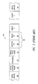
- FIG. 5 shows the correspondence between a sequence of servo data that is coded according to an embodiment of the invention and the bit regions of the servo wedge that contains the coded servo data.
- FIG. 6 is a diagram of servo-data Gray codes (which are not RLL coded) and the corresponding magnetization patterns for track identifiers in adjacent data tracks according to an embodiment of the invention.
- FIG. 7A is a plot of servo signals corresponding to read-head positions over and between the fourth and fifth data tracks of FIG. 6 according to an embodiment of the invention.
- FIG. 7B is a plot of servo signals corresponding to read-head positions over and between the fifth and sixth data tracks of FIG. 6 according to an embodiment of the invention.
- FIG. 8 is a block diagram of a servo circuit that can recover and decode a sequence of servo data that is coded according to an embodiment of the invention.
- FIG. 9 is a block diagram of a disk-drive system that incorporates the servo circuit of FIG. 8 according to an embodiment of the invention.
- Table I is a one-bit-to-four-bit (1/4) modulated code for coding servo data according to an embodiment of the invention. Although described as for coding servo data, one can use the 1/4 modulated code to code other types of data as well.
- Servo Logic Level Code Symbol 0 0000 1 0011 That is, each servo bit having a logic 0 level is coded as four consecutive logic 0 levels, and each uncoded servo bit having a logic 1 level is coded as two consecutive logic 0 levels followed by two consecutive logic 1 levels.
- the servo data may be coded with an arbitrary Run Length Limited (RLL) code.
- RLL Run Length Limited
- the servo data is to be RLL coded
- Most RLL codes have enough transitions in the code to allow a Viterbi detector ( FIG. 8 ) to merge for a successful sequence detection.
- the following sequence of uncoded servo data is discussed: (1) 011100100011 This sequence is coded as the following sequence of 1/4 coded servo data (the spaces are not part of the sequence but are included to highlight the correspondence between code symbols and the uncoded servo bits): (2) 0000 0011 0011 0011 0000 0000 0011 0000 0000 0011 0011
- FIG. 5 is a group of consecutive servo-data bit regions 50a-50h (sometimes called cells) in the servo wedge 16a ( FIG. 2 ) and the corresponding sequences of 1/4 coded and uncoded servo data according to an embodiment of the invention.
- the regions 50 are similar to the regions 40 of FIG. 4.
- the 1/4 code of Table I is compatible with a conventional dibit pattern and can reduce the number of regions 50 needed to store coded servo data because each region 50 can store more than one bit.
- a sequence of servo data coded using the 1/4 code of Table I always has an even number of consecutive logic 0's or an even number of consecutive logic 1's.
- each pair of 1/4-coded data bits can be written by halving the data.
- a servo track writer (not shown) can write the 16-bit 1/4-coded sequence 0011001100000011 of FIG. 5 as an 8-bit sequence 01010001.
- the 16-bit 1/4-coded sequence can be recovered by sampling each bit of the 8-bit written sequence twice. Therefore, by taking advantage of the data halving provided by the 1/4 code, one can increase the storage capacity of a disk.
- the 1/4 code is an even code ⁇ and is thus compatible with a conventional dibit pattern ⁇ because each dibit of 0 can be represented as data samples of 0000 and each dibit of 1 can be represented as data samples of 0011. Therefore, manufacturers need not modify their dibit servo-data writing format to use the 1/4 code.
- each region 50 can represent two bits
- servo data coded using the 1/4 code of Table I can increase a data-storage disk's ( FIG. 9 ) storage capacity because a 1/4-coded sequence occupies less track length, and thus a smaller area of the disk, than a sequence coded according to other codes.
- commonly owned U.S. Patent 6,201,652 discloses a 4/12 code that encodes each four-bit sequence of servo data as twelve bits. But the 4/12-code bits are such that two consecutive bits may not always be 00 or 11, and, therefore, a 4/12-coded sequence cannot be halved. Therefore, to write four bits of servo data using the 4/12 code requires twelve regions 50.
- the 1/4-coded data can have a better SNR performance than the 4/12-coded data while still occupying less disk space. Therefore, considering the space vs. performance trade off, the 1/4 code is often a better choice for coding servo data than the 4/12 code. Furthermore, the 1/4 code allows a manufacturer to increase the disk storage capacity even for dibit-coded formats.
- the 1/4 code can also increase the robustness of the servo circuit ( FIG. 8 ) because a sequence of 1/4-coded servo data includes only pairs of logic 1's that are separated by at least two logic 0's. This characteristic allows one to prune the Viterbi detector ( FIG. 8 ) of the servo circuit to "fit" the 1/4 code.
- a sequence of 4/12-coded servo data according to U.S. Patent 6,201,652 has the same characteristic ⁇ only pairs of logic 1's that are separated by at least two logic 0's ⁇ as but occupies more disk area than a sequence of 1/4-coded servo data as discussed above, the 4/12-coded data theoretically has better noise performance than the 1/4-coded data. That is, the servo signal that the read head ( FIG. 9 ) generates while reading a sequence of 4/12-coded servo data theoretically has a higher SNR ⁇ approximately 0.5 dB higher ⁇ than the servo signal that the read head generates while reading a sequence of 1/4-coded servo data. This higher SNR effectively increases the robustness of the Viterbi detector, and thus the robustness of the servo circuit, for recovering 4/12-coded servo data as compared to recovering 1/4-coded servo data.
- the 16 d -long 1/4-coded sequence is a fourth (25%) longer than its 12d-long 4/12-coded counterpart, this increase in length increases the noise performance of the 1/4-coded data by approximately 0.5 dB. That is, the servo signal that the read head ( FIG. 9 ) generates while reading this 1/4-coded data theoretically has an SNR that is approximately 0.5 dB higher than the SNR of the servo signal that the read head generates while reading a sequence of 4/12-coded servo data. Consequently, there is a tradeoff between servo-data density and noise performance; the higher the density, the lower the noise performance and vice versa.
- each region 50 of 1/4-coded servo data could represent three bits (three logic 0's or three logic 1's), and thus the servo circuit ( FIG.
- FIG. 6 is a diagram of the magnetization patterns corresponding to 16-bit Gray code track-identification words formed using the 1/4 code of Table I according to an embodiment of the invention. These code words are respectively stored in the track ID sections 30 ( FIG. 3 ) of the servo wedges 16 ( FIG. 2 ) in each group of eight adjacent tracks 14, here labeled tracks 0 - 7. Although these code words as shown are not RLL coded, one typically would RLL code them before 1/4 coding them.
- this Gray code coding scheme of FIG. 6 allows a head-position system ( FIG. 9 ) to identify the track 14 over which the read-write head ( FIG. 9 ) is located within ⁇ 1 track, even if the head is positioned between two tracks.
- the Gray code coding scheme constrains code changes between adjacent tracks 14 to replacement of a single pair of logic 1's (represented by dark squares) with a pair of logic 0's (represented by light squares) or replacement of a single pair of 0's with a pair of 1's.
- the only change in the code words between tracks 1 and 2 is that bits 7 and 8, which are logic 0's in track 1, are replaced with logic 1's in track 2.
- the only change between tracks 2 and 3 is that bits 11 and 12, which are logic 1's in track 2, are replaced with logic 0's in track 3.
- FIGS. 7A and 7B are plots of servo read signals corresponding to tracks 4 - 6 of FIG. 6 according to an embodiment of the invention.
- the magnetization patterns of FIG. 6 are such that if the read head (FIG. 9) is in between two tracks 14, the servo circuit (FIG. 8 ) ⁇ specifically the Viterbi detector in the servo circuit ⁇ recovers the code word corresponding to one of the two tracks. Consequently, the head-position system ( FIG. 9 ) can determine the location of the head within ⁇ 1 track accuracy.
- FIG. 7A is a plot of servo signals corresponding to the head (FIG. 9) being over track 4 or track 5 or in between tracks 4 and 5 of FIG. 6 .
- the servo signals are ideal, i.e., have no noise component (other than ISI).
- the y axis represents the amplitude of the servo signal in units of conventional PR4 sample values -1, 0, and +1, and the x axis represents time in units of the samples k of the servo signal.
- the head generates the servo signal 60 when it is directly over track 4.
- the head generates the servo signal 62 when it is directly over track 5.
- the head generates the servo signal 64 when it is halfway between tracks 4 and 5.
- the signals 60, 62 , and 64 are different. Specifically, the signal 62 transitions from -1, -1 (samples 9 and 10) to +1, +1 (samples 11 and 12) due to bits 9 and 10 of track 5 being logic 0 and bits 11 and 12 being logic 1.
- bits 9 - 12 of track 4 are logic 0, there are no flux changes so the signal 60 transitions from -1, -1, to 0 and levels out at 0.
- the signal 64 transitions from approximately -1, -1 to +0.5, +0.5, and thus is halfway in between the signals 60 and 62. In actuality, the signal 64 is likely to be closer to one of the signals 60 and 62 than to the other. Therefore, the servo circuit ( FIG. 8 ) recovers the coding word associated with the track ⁇ track 4 or track 5 in this example ⁇ closest to the head ( FIG. 9 ). The head-position circuit ( FIG. 9 ) then uses the information provided by the head-position bursts A - N ( FIG. 3 ) in tracks 4 and 5 to precisely position the head over the desired track ⁇ track 4 or track 5 in this example.
- FIG. 7B is a plot of read signals corresponding to the read head ( FIG. 9 ) being over track 5 or track 6 or in between tracks 5 and 6 of FIG. 6 .
- the servo signal 62 ⁇ which is identical to the servo signal 62 of FIG. 7A ⁇ is the signal that the head generates when it is directly over track 5.
- the head generates the servo signal 66 when it is directly over track 6.
- the head generates the servo signal 68 when it is halfway between tracks 5 and 6.
- the servo circuit FIG. 8
- the servo circuit recovers the Gray coded track-identification word associated with the track ⁇ track 5 or track 6 in this example ⁇ closest to the head, and thus allows the head-position circuit to locate the position of the head with respect to the disk ( FIG. 9 ).
- FIG. 8 is block diagram of a synchronous servo circuit 100, which can recover servo data coded using the 1/4 code of Table I according to an embodiment of the invention.
- the circuit 100 includes a gain and filter circuit 102, which adjusts the gain of and filters the servo signal from a read-write head ( FIG. 9 ).
- An analog-to-digital converter (ADC) 104 receives a sample clock (not shown) on a control bus 106 and generates digital samples, such as the samples k ( FIGS. 7A and 7B ), of the analog servo signal from the circuit 102.
- ADC analog-to-digital converter
- a finite-impulse-response (FIR) filter 108 equalizes the samples from the ADC 104, and timing and gain recovery loops 110 effectively synchronize the sample clock to the servo signal and maintain the gain of the circuit 100 at a desired level.
- the ADC 104, FIR 108, and loops 110 form a sample circuit 111.
- a Viterbi detector 112 recovers 1/4-coded servo data such as the location identifier 26 ( FIG. 3 ) from the servo-signal samples, and an optional sync-mark detector 114 recovers the servo sync mark 24 ( FIG. 3 ) from the servo signal. In one embodiment, the Viterbi detector 112 is pruned as discussed above in conjunction with FIG. 5.
- the Viterbi detector 112 recovers the sync mark 24.
- a decoder 116 decodes the recovered 1/4-coded servo data and sync mark from the Viterbi and sync-mark detectors 112 and 114, respectively.
- a position-burst demodulator 118 receives samples of the servo signal from the FIR 108 and generates a head-position-error signal, and a processor 120 controls the components of the servo circuit 100 via the control bus 106.
- a servo-data interface 122 interfaces the decoder 116, processor 120, and demodulator 118 to a disk-drive controller ( FIG. 9 ).
- circuit 102 ADC 104, FIR 108 , loops 110, Viterbi detector 112, decoder 116, processor 120, and operation of the servo circuit 100 are further discussed in previously incorporated U.S. Patent App. Ser. Nos. (Atty. Docket No. 99-S-190 (1678-22-1)) entitled "DATA-STORAGE DISK HAVING FEW OR NO SPIN-UP WEDGES AND METHOD FOR WRITING SERVO WEDGES ONTO THE DISK,” (Atty. Docket No.
- the timing-recovery loop of the loops 110 is further discussed in commonly owned U.S. Patent App. Ser. No. 09/387,146, filed August 31, 1999, entitled “DIGITAL TIMING RECOVERY USING BAUD RATE SAMPLING", which is incorporated by reference, and the gain-recovery loop of the loops 110 and the Viterbi detector 112 are also discussed in previously incorporated Patent App. Ser. No. 09/783,801, (Atty. Docket No. 99-S-185 (1678-21)), filed February 14, 2001, entitled “VITERBI DETECTOR AND METHOD FOR RECOVERING A BINARY SEQUENCE FROM A READ SIGNAL".
- the sync mark detector 114 is further discussed in previously incorporated Pat. App. Ser. No.
- FIG. 9 is a block diagram of a disk-drive system 200 that incorporates the servo circuit 100 of FIG. 8 according to an embodiment of the invention.
- the disk-drive system 200 includes a disk drive 202, which incorporates the servo circuit 100 of FIG. 8.
- the disk drive 202 includes a read-write head 204, a write channel 206 for generating and driving the head 204 with a write signal, and a write controller 208 for interfacing the write data to the write channel 206.
- the disk drive 202 also includes a read channel 210 for receiving servo and application-data read signals from the head 204 and for recovering data from these signals, and includes a read controller 212 for organizing the read data.
- the read channel 210 includes the servo circuit 100, which receives the servo signal from the head 204, recovers the servo data from the servo signal, and provides the recovered servo data to a head-position circuit 214.
- the disk drive 202 further includes a storage medium such as one or more disks 215, each of which may contain data on one or both sides and which may be magnetic, optical, or another type of storage disk.
- the disks 215 may be similar to the disk 10 of FIG. 1.
- the head 204 writes/reads the data stored on the disks 215, and is connected to a movable support arm 216.
- the head-position circuit 214 provides a control signal to a voice-coil motor (VCM) 218, which positionally maintains/radially moves the arm 216 so as to positionally maintain/radially move the head 204 over the desired data tracks on the disks 215.
- VCM voice-coil motor
- a spindle motor (SPM) 220 and a SPM control circuit 222 respectively rotates the disks 215 and maintains them at the proper rotational speed.
- the disk-drive-system 200 also includes write and read interface adapters 224 and 226 for respectively interfacing the disk-drive controller 213 to a system bus 228, which is specific to the system used.
- Typical system busses include ISA, PCI, S-Bus, Nu-Bus, etc.
- the system 200 typically has other devices, such as a random access memory (RAM) 230 and a central processing unit (CPU) 232 coupled to the bus 228.
- RAM random access memory
- CPU central processing unit
Landscapes
- Engineering & Computer Science (AREA)
- Signal Processing (AREA)
- Physics & Mathematics (AREA)
- Algebra (AREA)
- Pure & Applied Mathematics (AREA)
- Probability & Statistics with Applications (AREA)
- Theoretical Computer Science (AREA)
- Signal Processing For Digital Recording And Reproducing (AREA)
- Moving Of The Head To Find And Align With The Track (AREA)
Abstract
Description
| Servo Logic | Code Symbol | |
| 0 | 0000 | |
| 1 | 0011 |
(1) 011100100011
This sequence is coded as the following sequence of 1/4 coded servo data (the spaces are not part of the sequence but are included to highlight the correspondence between code symbols and the uncoded servo bits):
(2) 0000 0011 0011 0011 0000 0000 0011 0000 0000 0000 0011 0011
| Servo Logic | Code Symbol | |
| 0 | 000000 | |
| 1 | 000111 |
Claims (24)
- A coded binary sequence, comprising:a first group of consecutive bits, the first group having first and second equally sized portions and representing a first logic level, the bits in the first portion each having a second logic level and the bits in the second portion each having a third logic level; anda second group of consecutive bits, the second group having first and second equally sized portions and representing a fourth logic level, the bits in the first portion each having a fifth logic level and the bits in the second portion each having a sixth logic level.
- The binary sequence of claim 1 wherein:the first and second equally sized portions of the first group respectively comprise first and second halves of the first group; andthe first and second equally sized portions of the second group respectively comprise first and second halves of the second group.
- A coded binary sequence, comprising:an first group of consecutive bits each having a first logic level, the first group representing a second logic level; anda second group of consecutive bits, the second group having first and second portions and representing a third logic level, the bits in the first portion each having a fourth logic level and the bits in the second portion each having a fifth logic level.
- The binary sequence of claim 3, wherein the first and second groups each respectively comprise four consecutive bits.
- The binary sequence of claim 3, wherein the first and second portions of the second group respectively comprises first and second halves of the second group.
- A coded binary sequence, comprising:a first group of four consecutive bits each having a first logic level the first group representing a second logic level; anda second group of four consecutive bits respectively having a third logic level, the third logic level, a fourth logic level, and the fourth logic level, the second group representing a fifth logic level.
- A storage disk, comprising:disk sectors operable to store application data; andservo wedges that store servo data that includes ,a first group of consecutive bits, the first group having first and second equally sized portions and representing a first logic level, the bits in the first portion each having a second logic level and the bits in the second portion each having a third logic level; anda second group of consecutive bits, the second group having first and second equally sized portions and representing a fourth logic level, the bits in the first portion each having a fifth logic level and the bits in the second portion each having a sixth logic level.
- A Viterbi detector operable to:receive a signal that represents a binary sequence having a first group of consecutive bits each having a first logic level and a second group of consecutive bits, the second group having first and second portions, the bits in the first portion having the first logic level and the bits in the second portion having a second logic level, the first group representing the first logic level and the second group representing the second logic level; andrecover the binary sequence from the signal.
- The Viterbi detector of claim 8 wherein the binary sequence comprises a coded binary sequence.
- A servo circuit, comprising:a sample circuit operable to generate samples of a signal that represents a coded binary sequence having a first group of consecutive bits each having a first logic level and a second group of consecutive bits, the second group having first and second portions, the bits in the first portion having the first logic level and the bits in the second portion having a second logic tevel, he first group representing the first logic level and the second group representing the second logic level; anda Viterbi detector coupled to the sample circuit and operable to recover the coded binary sequence from the samples of the signal.
- A disk-drive system, comprising:a data-storage disk having a surface, data sectors at respective locations of the surface, and servo wedges that store servo data that includes a first group of consecutive bits each having a first logic level and a second group having first and second portions of consecutive bits, the bits in the first portion having the first logic level and the bits in the third portion having a second logic level, the first group representing the first logic level and the second group representing the second logic level;a motor coupled to and operable to rotate the disk;a read head operable to generate a servo signal that represents the servo dataand having a position with respect to the surface of the data-storage disk; a read-head positioning circuit operable to move the read head over the surface of the disk; anda servo circuit coupled too the read head and operable to recover the servo data from the servo signal.
- The disk-drive system of claim 11 wherein the servo circuit comprises: a sample circuit operable to generate samples of the servo signal; and a Viterbi detector coupled to the sample circuit and operable to recover the servo data from the samples of the servo signal.
- The disk-drive system of claim 11 or circuit of claim 10 wherein the servo circuit comprises a decoder operable to decode the recovered servo data.
- The disk-drive system of claim 11 wherein the read head comprises a read-write head.
- A method comprising:coding a first logic level as a first group of consecutive bits, the first group having first and second equally sized portions, the bits in the first portion each having a second logic level and the bits in the second portion each having a third logic level; andcoding a fourth logic level as a second group of consecutive bits, the second group having first and second equally sized portions, the bits in the first portion each having a fifth logic level and the bits in the second portion each having a sixth logic level.
- The method of claim 15 or sequence of claims 3 or 6 wherein:the first, second, third and fifth logic values equal a logic 0; andthe fourth and sixth logic values equal a logic 1; orthe first, second and fourth logic levels equal logic 0,and the third and fifth logic levels equal logic 1; orthe first, second and third logic values equal a logic 0, andthe fourth and fifth logic values equal a logic 1.
- The method of claim 20 wherein the coding comprises:coding the first logic level as a first group of four consecutive bits; andcoding the fourth logic level as a second group of four consecutive bits.
- The method of claim 15 wherein the first and second portions of the first group and the first and second portions of the second group respectively comprise first and second halves of the first and second groups.
- A method comprising:coding a first bit of servo data as a first group of four consecutive bits each having a first logic level; andcoding a second bit of servo data as a second group of four consecutive bits respectively having the first logic level, the first logic level, a second logic level, and the second logic level.
- The method of claim 19 or detector of claim 13 wherein:the first logic level equals a logic 0; andthe second logic level equals a logic 1.
- A method comprising:writing a first code symbol into a servo wedge of a data-storage disk, the first code symbol having a length and representing the first logic level; andwriting a second code symbol into the servo wedge, the second code symbol having the length or approximately the length, a first portion, and a second portion, and representing a second logic level, the first portion having a different value than the second portion.
- The method of claim 21 wherein:the first and second code symbols each comprise a number of code bits; andthe lengths of the first and second code symbols are each less than the product of the number and a length of a servo-bit region.
- The method of claim 19 or 21 wherein:the first code symbol or bit represents a logic 0; andthe second code symbol or bit represents a logic 1.
- The method of claim 21 wherein the first and second portions of the second code symbol are or are approximately half as long as the second code word.
Applications Claiming Priority (4)
| Application Number | Priority Date | Filing Date | Title |
|---|---|---|---|
| US30150601P | 2001-06-28 | 2001-06-28 | |
| US301506P | 2001-06-28 | ||
| US09/994,009 US20030011918A1 (en) | 2001-06-28 | 2001-11-05 | Data code and method for coding data |
| US994009 | 2001-11-05 |
Publications (2)
| Publication Number | Publication Date |
|---|---|
| EP1271479A2 true EP1271479A2 (en) | 2003-01-02 |
| EP1271479A3 EP1271479A3 (en) | 2006-12-06 |
Family
ID=26972416
Family Applications (1)
| Application Number | Title | Priority Date | Filing Date |
|---|---|---|---|
| EP02253884A Withdrawn EP1271479A3 (en) | 2001-06-28 | 2002-05-31 | A data code and method for coding data |
Country Status (3)
| Country | Link |
|---|---|
| US (1) | US20030011918A1 (en) |
| EP (1) | EP1271479A3 (en) |
| JP (1) | JP2003100030A (en) |
Cited By (1)
| Publication number | Priority date | Publication date | Assignee | Title |
|---|---|---|---|---|
| CN116665836A (en) * | 2023-07-26 | 2023-08-29 | 国仪量子(合肥)技术有限公司 | Editing and storing method, reading and playing method and electronic equipment for sequence data |
Families Citing this family (7)
| Publication number | Priority date | Publication date | Assignee | Title |
|---|---|---|---|---|
| US7839594B2 (en) * | 2001-06-28 | 2010-11-23 | Stmicroelectronics, Inc. | Data-storage disk having few or no spin-up wedges and method for writing servo wedges onto the disk |
| TWI260645B (en) * | 2003-06-19 | 2006-08-21 | Samsung Electronics Co Ltd | Apparatus and method for detecting binary data |
| KR100975056B1 (en) * | 2003-09-16 | 2010-08-11 | 삼성전자주식회사 | Data playback device and method |
| US7242546B2 (en) * | 2003-10-13 | 2007-07-10 | Seagate Technology Llc | Determining a location based on a cyclic bit sequence containing consecutively-placed identical bit-groups |
| US7193801B2 (en) * | 2004-11-18 | 2007-03-20 | Agere Systems, Inc. | Method and apparatus for testing a servo circuit of a read/write head system |
| KR100712503B1 (en) * | 2005-01-13 | 2007-05-02 | 삼성전자주식회사 | Servo data creation method of hard disk drive and self-servo recording method using the same |
| US9768988B1 (en) * | 2012-12-20 | 2017-09-19 | Seagate Technology Llc | Jointly optimizing signal equalization and bit detection in a read channel |
Citations (1)
| Publication number | Priority date | Publication date | Assignee | Title |
|---|---|---|---|---|
| US6233715B1 (en) | 1998-12-30 | 2001-05-15 | Texas Instruments Incorporated | Synchronous servo gray code detector using a PR4 matched filter |
Family Cites Families (10)
| Publication number | Priority date | Publication date | Assignee | Title |
|---|---|---|---|---|
| US5576904A (en) * | 1994-09-27 | 1996-11-19 | Cirrus Logic, Inc. | Timing gradient smoothing circuit in a synchronous read channel |
| US5661760A (en) * | 1995-10-23 | 1997-08-26 | Quantum Corporation | Wide biphase digital servo information detection, and estimation for disk drive using servo Viterbi detector |
| US5796535A (en) * | 1995-05-12 | 1998-08-18 | Cirrus Logic, Inc. | Sampled amplitude read channel employing a user data frequency synthesizer and a servo data frequency synthesizer |
| JPH0990333A (en) * | 1995-09-26 | 1997-04-04 | Fuji Photo Film Co Ltd | Liquid crystal display device |
| US5812336A (en) * | 1995-12-05 | 1998-09-22 | Cirrus Logic, Inc. | Fixed sample rate sampled amplitude read channel for zoned magnetic recording |
| US5909336A (en) * | 1997-02-18 | 1999-06-01 | Texas Instruments Incorporated | Position detection scheme for headerless disk controller |
| US6112117A (en) * | 1997-05-06 | 2000-08-29 | Cardiac Pacemakers, Inc. | Method and apparatus for treating cardiac arrhythmia using electrogram features |
| US6201652B1 (en) * | 1998-05-29 | 2001-03-13 | Stmicroelectronics, Inc. | Method and apparatus for reading and writing gray code servo data to magnetic medium using synchronous detection |
| US6400288B1 (en) * | 1998-09-22 | 2002-06-04 | Seagate Technology Llc | Method and apparatus for generating code words with shifted tribit error protection |
| US6606728B1 (en) * | 1999-06-23 | 2003-08-12 | Agere Systems Inc. | Rate (M/N) code encoder, detector, and decoder for control data |
-
2001
- 2001-11-05 US US09/994,009 patent/US20030011918A1/en not_active Abandoned
-
2002
- 2002-05-31 EP EP02253884A patent/EP1271479A3/en not_active Withdrawn
- 2002-06-27 JP JP2002187783A patent/JP2003100030A/en active Pending
Patent Citations (1)
| Publication number | Priority date | Publication date | Assignee | Title |
|---|---|---|---|---|
| US6233715B1 (en) | 1998-12-30 | 2001-05-15 | Texas Instruments Incorporated | Synchronous servo gray code detector using a PR4 matched filter |
Cited By (2)
| Publication number | Priority date | Publication date | Assignee | Title |
|---|---|---|---|---|
| CN116665836A (en) * | 2023-07-26 | 2023-08-29 | 国仪量子(合肥)技术有限公司 | Editing and storing method, reading and playing method and electronic equipment for sequence data |
| CN116665836B (en) * | 2023-07-26 | 2023-10-27 | 国仪量子(合肥)技术有限公司 | Editing and storing method, reading and playing method and electronic equipment for sequence data |
Also Published As
| Publication number | Publication date |
|---|---|
| JP2003100030A (en) | 2003-04-04 |
| US20030011918A1 (en) | 2003-01-16 |
| EP1271479A3 (en) | 2006-12-06 |
Similar Documents
| Publication | Publication Date | Title |
|---|---|---|
| US7027247B2 (en) | Servo circuit having a synchronous servo channel and method for synchronously recovering servo data | |
| US7203015B2 (en) | Method and apparatus for decoding sync marks in a disk | |
| JP3162253B2 (en) | Decoding method of head positioning servo information and synchronous servo data detection subsystem | |
| US6201652B1 (en) | Method and apparatus for reading and writing gray code servo data to magnetic medium using synchronous detection | |
| US5737142A (en) | Servo track address channel code for PR4 magnetic recording | |
| US8379340B2 (en) | Circuit and method for detecting the phase of a servo signal | |
| US7430082B2 (en) | Circuit and method for demodulating a servo position burst | |
| US8131920B2 (en) | Method and system for dynamically allocating read and write sequence randomizer | |
| US6233715B1 (en) | Synchronous servo gray code detector using a PR4 matched filter | |
| US20030011918A1 (en) | Data code and method for coding data | |
| US6108150A (en) | Formation of servo information and method for servo control therefor in disk drive data storage system | |
| US6657800B1 (en) | Viterbi detector and method for recovering a binary sequence from a read signal | |
| US7382568B2 (en) | Circuit and method for detecting a servo wedge on spin-up of a data-storage disk | |
| JP2003045120A (en) | Disk storage device and read method applied to the device | |
| EP0731968A1 (en) | Retrieving data recorded at different bit densities | |
| US6909681B2 (en) | Optical disk and optical disk apparatus | |
| US6865042B2 (en) | Embedded servo patterning methods and apparatus | |
| US6496312B2 (en) | Use of snake-in-the-box codes for reliable identification of tracks in servo fields of a disk drive | |
| US7839594B2 (en) | Data-storage disk having few or no spin-up wedges and method for writing servo wedges onto the disk | |
| US7126775B1 (en) | Servo track address channel code for d=1 magnetic recording | |
| US6404577B1 (en) | Trellis encoding and decoding of track identification indicia | |
| US6868515B2 (en) | Formatting method and apparatus for a direct access storage device | |
| US6587291B2 (en) | Asynchronously sampling wide bi-phase codes | |
| JP2006506773A (en) | Multidimensional encoding method for high density storage media applications | |
| US6577460B1 (en) | Method and apparatus for improving track format efficiency in a direct access storage device |
Legal Events
| Date | Code | Title | Description |
|---|---|---|---|
| PUAI | Public reference made under article 153(3) epc to a published international application that has entered the european phase |
Free format text: ORIGINAL CODE: 0009012 |
|
| AK | Designated contracting states |
Kind code of ref document: A2 Designated state(s): AT BE CH CY DE DK ES FI FR GB GR IE IT LI LU MC NL PT SE TR |
|
| AX | Request for extension of the european patent |
Free format text: AL;LT;LV;MK;RO;SI |
|
| PUAL | Search report despatched |
Free format text: ORIGINAL CODE: 0009013 |
|
| AK | Designated contracting states |
Kind code of ref document: A3 Designated state(s): AT BE CH CY DE DK ES FI FR GB GR IE IT LI LU MC NL PT SE TR |
|
| AX | Request for extension of the european patent |
Extension state: AL LT LV MK RO SI |
|
| RIC1 | Information provided on ipc code assigned before grant |
Ipc: G11B 27/30 20060101AFI20061031BHEP |
|
| 17P | Request for examination filed |
Effective date: 20070525 |
|
| AKX | Designation fees paid |
Designated state(s): DE FR GB IT |
|
| 17Q | First examination report despatched |
Effective date: 20070831 |
|
| STAA | Information on the status of an ep patent application or granted ep patent |
Free format text: STATUS: THE APPLICATION IS DEEMED TO BE WITHDRAWN |
|
| 18D | Application deemed to be withdrawn |
Effective date: 20090123 |