EP1271476A2 - Burst position error data write method and magnetic disk unit - Google Patents
Burst position error data write method and magnetic disk unit Download PDFInfo
- Publication number
- EP1271476A2 EP1271476A2 EP01308470A EP01308470A EP1271476A2 EP 1271476 A2 EP1271476 A2 EP 1271476A2 EP 01308470 A EP01308470 A EP 01308470A EP 01308470 A EP01308470 A EP 01308470A EP 1271476 A2 EP1271476 A2 EP 1271476A2
- Authority
- EP
- European Patent Office
- Prior art keywords
- burst
- error data
- position error
- magnetic disk
- write
- Prior art date
- Legal status (The legal status is an assumption and is not a legal conclusion. Google has not performed a legal analysis and makes no representation as to the accuracy of the status listed.)
- Granted
Links
Images





Classifications
-
- G—PHYSICS
- G11—INFORMATION STORAGE
- G11B—INFORMATION STORAGE BASED ON RELATIVE MOVEMENT BETWEEN RECORD CARRIER AND TRANSDUCER
- G11B5/00—Recording by magnetisation or demagnetisation of a record carrier; Reproducing by magnetic means; Record carriers therefor
- G11B5/012—Recording on, or reproducing or erasing from, magnetic disks
-
- G—PHYSICS
- G11—INFORMATION STORAGE
- G11B—INFORMATION STORAGE BASED ON RELATIVE MOVEMENT BETWEEN RECORD CARRIER AND TRANSDUCER
- G11B5/00—Recording by magnetisation or demagnetisation of a record carrier; Reproducing by magnetic means; Record carriers therefor
- G11B5/48—Disposition or mounting of heads or head supports relative to record carriers ; arrangements of heads, e.g. for scanning the record carrier to increase the relative speed
- G11B5/58—Disposition or mounting of heads or head supports relative to record carriers ; arrangements of heads, e.g. for scanning the record carrier to increase the relative speed with provision for moving the head for the purpose of maintaining alignment of the head relative to the record carrier during transducing operation, e.g. to compensate for surface irregularities of the latter or for track following
- G11B5/596—Disposition or mounting of heads or head supports relative to record carriers ; arrangements of heads, e.g. for scanning the record carrier to increase the relative speed with provision for moving the head for the purpose of maintaining alignment of the head relative to the record carrier during transducing operation, e.g. to compensate for surface irregularities of the latter or for track following for track following on disks
- G11B5/59633—Servo formatting
- G11B5/59655—Sector, sample or burst servo format
Definitions
- the present invention generally relates to burst position error data write methods and magnetic disk units, and more particularly to a burst position error data write method and a magnetic disk unit which write on a magnetic disk burst position error data used for correcting a positional error of a burst pattern, so that the burst position error data can be positively read from the magnetic disk when reading servo information which are written in advance on the magnetic disk.
- the servo information is written in advance within the data in a data area, without providing an exclusive data area therefor.
- the servo information is used to accurately detect the movement of a head in an off-track direction on the magnetic disk.
- the servo information is written on the magnetic disk in advance by use of a servo track writer (STW) designed exclusively therefor.
- STW servo track writer
- the servo information is written with a servo frame format shown in FIG. 1, for example.
- the servo frame format includes a read/write recovery region for absorbing a transient that is generated when switching from a data write operation to a servo read operation, a servo mark region for confirming a start of a servo pattern region, a Gray code region in which cylinder address information is encoded, a position region in which a burst signal is written, a gap region for indicating an end of the servo frame, and the like.
- the position region includes a burst pattern region which is written with a burst pattern for correcting an error within one track, and a data region which is written with a burst position error data for correcting a positional error of the burst pattern.
- the burst position error data is sometimes also referred to as a repeatable run-out (RRO) correction data for correcting the repeatable run-out (RRO).
- FIG. 2 is a diagram showing an arrangement of the burst position error data written on the magnetic disk by a conventional burst position error data write method, for a case where a feed pitch is 1/2 track.
- a bold solid line indicates a boundary line of the adjacent cylinders (or tracks), and a broken line indicates a center of a cylinder (or track).
- a vertical direction corresponds to a radial direction of the magnetic disk, and a horizontal direction corresponds to a circumferential direction of the magnetic disk.
- a burst position error data 2 which is written next to a burst pattern 1, is used to correct an error of a write head 3 from the center of the cylinder to which the write head 3 is on-track, and to correct an error of a read head 4 from the center of the cylinder to which the read head 4 is on-track.
- a core width 3-CW of the write head 3 is approximately 75% of a cylinder width 6, and a code width 4-CW of the read head 4 is approximately 50% of the cylinder width 6. For this reason, a region 5 in which no burst position error data is written is generated in a position region as indicated by cross-hatching in FIG. 2.
- the read head 4 can read the burst position error data 2 as indicated by P1 in FIG. 2.
- the read head 4 scans a region which is written with the burst position error data 2 as indicated by P2 in FIG. 2, and there is a possibility in this case that the burst position error data 2 cannot be read by the read head 4.
- FIG. 3 is a diagram showing an arrangement of the burst position error data written on the magnetic disk by this conceivable bust position error data write method, for a case where the feed pitch is 1/2 track.
- those parts which are the same as those corresponding parts in FIG. 2 are designated by the same reference numerals, and a description thereof will be omitted.
- the burst position error data 2 is overwritten in the circumferential direction of the magnetic disk, so as to prevent generation of the region 5 in which no burst position error data 2 is written, as in the case shown in FIG. 2.
- the burst position error data 2 is repeatedly written, portions where the burst position error data 2 is overwritten is generated in the radial direction of the magnetic disk, to thereby generate a write phase error 7 as shown in FIG. 3.
- burst position error data 2 is overwritten in the radial direction occur when the core width 3-CW of the write head 3 is greater than two times the pitch of the boundaries of the burst pattern 1, that is, when the code width 3-CW of the write head 3 is greater than the cylinder width 6.
- burst position error data 2 including such a write phase error 7 is read, there is a possibility that the burst position error data 2 will not be recognized correctly.
- the burst position error data which is written on the magnetic disk by the conceivable burst position error data write method studied by the present inventors can positively be read even when the positional error of the read head from the target cylinder immediately after the seek is relatively large, because the read head will always scan the region which is written with the burst position error data.
- the write phase error which is caused by the repeated writing of the burst position error data there is a possibility that the burst position error data cannot be recognized correctly.
- Another and more specific object of the present invention is to provide a burst position error data write method and a magnetic disk unit, which can write burst position error data of control information on a magnetic disk in such a manner that the burst position error data can positively be read from the magnetic disk.
- WHD denotes a core width of a write head
- K denotes a pitch of burst boundaries of the burst pattern
- M denotes a number of regions of the burst position error data which need to be provided after the burst pattern.
- a further object of the present invention is to provide a burst position error data write method for writing, on a magnetic disk, a burst position error data which is used for correcting a positional error of a burst pattern which is used for correcting an error within one track, next to the burst pattern, comprising the step of writing the burst position error data by moving a write head to a position offset in a direction opposite to and by an offset amount identical to an error amount the write head is offset when switching from a normal data write operation to a normal data read operation.
- the burst position error data write method of the present invention it is possible to write the burst position error data of the control information on the magnetic disk in such a manner that the burst position error data can positively be read from the magnetic disk.
- the magnetic disk unit of the present invention it is possible to write the burst position error data of the control information on the magnetic disk in such a manner that the burst position error data can positively be read from the magnetic
- Still another object of the present invention is to provide a magnetic disk unit which writes, on a magnetic disk, a burst position error data which is used for correcting a positional error of a burst pattern which is used for correcting an error within one track, next to the burst pattern, comprising control means for moving a write head to a position offset in a direction opposite to and by an offset amount identical to an error amount the write head is offset when switching from a normal data write operation to a normal data read operation; and write means for writing the burst position error data on the magnetic disk by the write head the position of which is controlled by the control means.
- the magnetic disk unit of the present invention it is possible to write the burst position error data of the control information on the magnetic disk in such a manner that the burst position error data can positively be read from the magnetic disk.
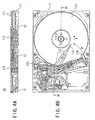
- FIGS. 4A and 4B respectively are diagrams showing a basic structure of an embodiment of the magnetic disk unit according to the present invention.
- the present invention is applied to a hard disk drive (HDD) which is provided with a hard disk.
- this embodiment of the magnetic disk unit employs an embodiment of the burst position error data write method according to the present invention.
- FIG. 4B is a plan view showing the HDD with a top portion thereof removed
- FIG. 4A is a cross sectional view of the HDD taken along a line IV-IV in FIG. 4B.
- a HDD 10 generally includes a disk enclosure (DE) 11 and a printed circuit assembly (PCA) 12.
- Hard disks 111, a spindle motor (SPM) 112, a voice coil motor (VCM) 113, arms 114, heads 115, ramp mechanisms 116 and the like are provided within the disk enclosure 11.
- the disk 111 is rotated in an arrow direction A by the spindle motor 112.
- the VCM 113 turns the arm 114 in an arrow direction B, and moves the head 115 in a radial direction of the disk 111, so as to make the head 115 scan a desired track during a seek, for example.
- the ramp mechanism 116 is disposed on the outer side of the disk 111, and is provided to engage a tip end of the arm 114 and maintain the head 115 separated from the disk 111.
- the head 115 includes a write head and a read head.
- the basic structure of the magnetic disk unit is not limited to the basic structure shown in FIG. 4, and various known basic structures may be employed.
- the present invention is applicable to a magnetic disk unit having any basic structure, as long the magnetic disk unit has a function of writing burst position error data of servo information on the disk 111 as will be described later.
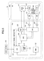
- FIG. 5 is a system block diagram showing a structure of a control system of this embodiment of the magnetic disk unit.
- the disk 111, the spindle motor 112, the voice coil motor 113, the head 115, a head IC 117 and the like are provided within the disk enclosure 11.
- a hard disk controller (HDC) 121, a RAM 122, a flash ROM 123, a MPU 124, a read channel (RDC) 125, a servo controller (SVC) 126, drivers 127 and 128 and the like are provided within the PCA 12.
- the head IC 117 subjects a signal read from the disk 111 by the head 115 to a predetermined process including an amplifying process and the like, before supplying the read signal to the read channel 125 within the PCA 12.
- the head IC 117 also supplies a write signal received from the MPU 124 to the head 115 so as to write the write signal on the disk 111.
- the voice coil motor 113 drives the arm 114 based on a control signal which is received from the servo controller 126 within the PCA 12 via the driver 127.
- a load operation which loads the head 115 from the ramp mechanism 116 onto the disk 111, and an unload operation which unloads the head 115 from the disk 111 onto the ramp mechanism 116, are carried out by driving the arm 114.
- the spindle motor 112 rotates the disk 111 based on a control signal which is received from the servo controller 126 within the PCA 12 via the driver 128.
- the HDC 121 supplies a read/write instruction to the MPU 124 based on an instruction from a host system 100.
- the MPU 124 controls the operation of the control system including the servo controller 126, based on the instruction from the HDC 121 and the read signal which is received via the read channel 125.
- the write signal is supplied to the head IC 117 within the disk enclosure 11 via the HDC 121 and the MPU 124, and the read signal from the head IC 117 is supplied to the MPU 124 and the HDC 121 via the read channel 125.
- the read signal which is supplied to the HDC 121 is supplied to the host system 100.
- the flash ROM 123 stores various data which are used when the MPU 124 operates, and the RAM 122 temporarily stores various data which are used when the MPU 124 and the HDC 121 operate.
- control system of the magnetic disk unit is of course not limited to the structure shown in FIG. 5, and various known structures may be used for the control system.
- control system may have any structure as long as the control system includes the function of writing the burst position error data of the servo information on the disk 111 as will be described later.
- FIG. 6 is a diagram for explaining a write head positioning method when carrying out a normal data write.
- a read head 34 is on-track with respect to a burst boundary 41 of a burst pattern 31 for correcting an error within one track.
- the burst boundary 41 is a boundary line of the burst pattern 31 along the circumferential direction of the disk 111.
- the write head 33 is located at a position deviated from the burst boundary 41 by an error amount d in the radial direction of the disk 111, due to causes such as an error in a YAW angle and an error in the mounting position of the head 115 with respect to the arm 114.
- the write head 33 when the center of a target cylinder (or track) matches the burst boundary 41, the write head 33 is located at the position deviated by the error amount d from the center of this target cylinder.
- This error amount d indicates an error in the radial direction between the center of the core width of the read head 34 and the center of the core width of the write head 33. Accordingly, the write head 33 writes normal data in a region 38 indicated by the hatching in FIG. 6.
- FIG. 7 is a diagram for explaining a positional relationship of the read head 34 and the write head 33 when reading the normal data which is written on the target cylinder as described above.
- those parts which are the same as those corresponding parts in FIG. 6 are designated by the same reference numerals, and a description thereof will be omitted.
- the read head 34 when reading the normal written on the target cylinder, the read head 34 is moved, not to the center of the target cylinder, but to a position offset by the error amount d of the read head 34 in the radial direction with respect to the read head 34, so as to read the data.
- Such a control itself of the head 115 during the write and the read of the normal data is known.
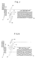
- FIG. 8 is a diagram for explaining the positional relationship of the read head 34 and the write head 33 when writing the burst position error data in this embodiment.
- those parts which are the same as those corresponding parts in FIG. 6 are designated by the same reference numerals, and a description thereof will be omitted.
- the burst position error data is written by moving the write head 33 to a position offset in an opposite direction as shown in FIG. 8 by an offset amount identical to the error amount d the write head 33 is offset when switching from the normal data write operation shown in FIG. 6 to the normal data read operation shown in FIG. 7.
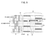
- FIG. 9 is a diagram showing an arrangement of the burst position error data written by this embodiment, for a case where the feed pitch is 1/2 - track.
- a bold solid line indicates the boundary line of the adjacent cylinders (or tracks), and a broken line indicates the center of the cylinder ⁇ or track).
- a vertical direction corresponds to the radial direction of the disk 111
- a horizontal direction corresponds to the circumferential direction of the disk 111.
- a burst position error data 32 which is written next to a burst pattern 31, is used to correct an error of the write head 33 from the center of the cylinder to which the write head 33 is on-track, and to correct an error of the read head 34 from the center of the cylinder to which the read head 34 is on-track.
- a data region in which the data write and the data read are carried out is provided next to the burst position error data 32 in the circumferential direction of the disk 111.
- a core width 33-CW of the write head 33 is approximately 75% of a cylinder width 36, and a code width 34-CW of the read head 34 is approximately 50% of the cylinder width 36. For this reason, a region 35 in which no burst position error data is written is generated in a position region as indicated by cross-hatching in FIG. 9. In a case where a positional error of the read head 34 from the target cylinder immediately after the seek is relatively small, the read head 34 can read the burst position error data 32 similarly to the case described above in conjunction with FIG. 2.
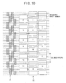
- FIG. 10 is a diagram for explaining a relationship of a burst number and a circumferential direction position on a disk when writing the burst position error data.
- those parts which are the same as those corresponding parts in FIG. 9 are designated by the same reference numerals, and a description thereof will be omitted.
- a reference burst position is determined.
- the reference burst position is determined to an outermost peripheral cylinder, an innermost peripheral cylinder or an arbitrary cylinder of the disk 111, for example.
- the reference burst position may be determined to the position of an arbitrary burst boundary 41.
- the positional relationship of the burst number which is the radial direction position from the reference burst position, and the peripheral direction position, is uniquely determined depending on the number of regions of the burst position error data 32 provided after the burst pattern 31 in the scanning direction of the head 115 (direction opposite to the rotating direction of the disk 111).
- FIG. 10 shows a case where the feed pitch is 1/3 track, the reference burst number 0 is the cylinder number xxx, and three regions of the burst position error data 32 are provided after the burst pattern 31 in the circumferential direction of the disk 111.
- FIG. 11 is a flow chart for explaining a burst position error data read process.
- the process shown in FIG. 11 is carried out by the MPU 124 shown in FIG. 5 when carrying out a calibration, for example, but the process may be carried out by the MPU 124 together with the HDC 121.
- a step S1 controls the read head 34 to be on-track on the target bust boundary 41, and a step S2 starts detection of the burst position error data.
- a step S3 detects a servo frame number (SF. No. XX), and a step S4 decides whether or not the servo information is detected. If the decision result in the step S4 is NO, the process returns to the step S3. On the other hand, if the decision result in the step S4 is YES, a step S5 detects a present position error signal PESNOW.
- a step S6 reads a burst position error data PES (SF. No. XX) corresponding to the servo frame number (SF. No. XX).
- a step S8 decides whether or not all of the servo frames have ended.
- a step S10 decides whether or not the above described series of processes have been carried out and ended for the normal number of revolutions SS. If the decision result in the step S10 is NO, a step S11 initializes the servo frame number (SF. No. XX) to 0, and the process returns to the step S5. The process ends if the decision result in the step S10 is YES.
- FIG. 12 is a flow chart for explaining a burst position error data write process.
- the process shown in FIG. 12 is carried out by the MPU 124 shown in FIG. 5, but the process may be carried out by the MPU 124 together with the HDC 121.
- a step S21 sets a start timer within the MPU 124. This start timer determines a write start timing of the burst position error data.
- a step S22 moves the write head 33 to a position offset in an opposite direction as shown in FIG. 8 by an offset amount identical to the error amount d the write head 33 is offset when switching from the normal data write operation shown in FIG. 6 to the normal data read operation shown in FIG. 7.
- a step S23 detects the servo frame number SF. No. XX, and a step S24 decides whether or not the burst pattern of the servo information is detected. If the decision result in the step S24 is NO, the process returns to the step S23.
- a step S25 decides whether or not all of the burst patterns have ended. The process advances to a step S26 if the decision result in the step S25 is YES.
- the step S26 starts count-down of the start timer described above, and a step S27 decides whether or not the count-down of the start timer has ended. If the decision result in the step S27 is YES, a step S28 reads from the memory means such as the RAM 122 and the ROM 123 the burst position error data PES (SF. No. XX) which corresponds to the servo frame number SF. No. XX and was obtained by the operation described above. A step S29 writes the servo position error data on the disk 111 by the write head 33 which is located at the above described position, and a step S30 decides whether or not all of the servo frames have ended.
- the memory means such as the RAM 122 and the ROM 123 the burst position error data PES (SF. No. XX) which corresponds to the servo frame number SF. No. XX and was obtained by the operation described above.
- a step S29 writes the servo position error data on the disk 111
- the process ends if the decision result in the step S30 is YES.
- the burst position error data write process shown in FIG. 12 may be carried out by a servo track writer (STW) exclusively for writing the servo information, so that the burst position error data is written in advance on the disk 111 together with the servo information.
- STW servo track writer
- N is an integer greater than or equal to one.
- FIG. 13 is a diagram showing a state of the burst position error data 32 written on the disk 111 for the cases 1 ⁇ , 2 ⁇ and 3 ⁇ described above.
- (a) shows the case 1 ⁇
- those parts which are the same as those corresponding parts in FIG. 9 are designated by the same reference numerals, and a description thereof will be omitted.
Landscapes
- Moving Of The Head To Find And Align With The Track (AREA)
- Digital Magnetic Recording (AREA)
Abstract
Description
Claims (15)
- A burst position error data write method for writing, on a magnetic disk, a burst position error data which is used for correcting a positional error of a burst pattern which is used for correcting an error within one track, next to the burst pattern, characterized by the step of:(a) writing the burst position error data so as to satisfy a relationship M = N when (N-1)K < WHD < NK, where WHD denotes a core width of a write head, K denotes a pitch of burst boundaries of the burst pattern, and M denotes a number of regions of the burst position error data which need to be provided after the burst pattern.
- The burst position error data write method as claimed in claim 1, characterized in that said step (a) is carried out during a calibration of a magnetic disk unit.
- The burst position error data write method as claimed in claim 1 or 2, characterized in that said step (a) is carried out by a servo track writer (STW) exclusively for writing servo information.
- A burst position error data write method for writing, on a magnetic disk, a burst position error data which is used for correcting a positional error of a burst pattern which is used for correcting an error within one track, next to the burst pattern, characterize by the step of:(a) writing the burst position error data by moving a write head to a position offset in a direction opposite to and by an offset amount identical to an error amount the write head is offset when switching from a normal data write operation to a normal data read operation.
- The burst position error data write method as claimed in claim 4, characterized in that said step (a) matches a center of a core width of the write head to a center of a target cylinder on the magnetic disk when the center of the target cylinder matches a burst boundary of the burst pattern.
- The burst position error data write method as claimed in claim 4 or 5, characterized in that said step (a) is carried out during a calibration of a magnetic disk unit.
- The burst position error data write method as claimed in any of claims 4 to 6, characterized in that said step (a) is carried out by a servo track writer (STW) exclusively for writing servo information.
- The burst position error data write method as claimed in any of claims 4 to 7, characterized in that said step (a) writes the burst position error data so as to satisfy a relationship M = N when (N-1)K < WHD < NK, where WHD denotes a core width of the write head, K denotes a pitch of burst boundaries of the burst pattern, and M denotes a number of regions of the burst position error data which need to be provided after the burst pattern.
- A magnetic disk unit which writes, on a magnetic disk, a burst position error data which is used for correcting a positional error of a burst pattern which is used for correcting an error within one track, next to the burst pattern, characterized by:control means for controlling a position of a write head so as to satisfy a relationship M = N when (N-1)K < WHD < NK, where WHD denotes a core width of a write head, K denotes a pitch of burst boundaries of the burst pattern, and M denotes a number of regions of the burst position error data which need to be provided after the burst pattern; andwrite means for writing the burst position error data on the magnetic disk by the write head the position of which is controlled by said control means.
- The magnetic disk unit as claimed in claim 9, characterized in that said write means writes the burst position error data on the magnetic disk during a calibration of the magnetic disk unit.
- The magnetic disk unit as claimed in claim 9 or 10, characterized in that a core width of the write head is smaller than a core width of a read head.
- A magnetic disk unit which writes, on a magnetic disk, a burst position error data which is used for correcting a positional error of a burst pattern which is used for correcting an error within one track, next to the burst pattern, characterized by:control means for moving a write head to a position offset in a direction opposite to and by an offset amount identical to an error amount the write head is offset when switching from a normal data write operation to a normal data read operation; andwrite means for writing the burst position error data on the magnetic disk by the write head the position of which is controlled by said control means.
- The magnetic disk unit as claimed in claim 12, characterized in that said control means controls the position of the write head so as to match a center of a core width of the write head to a center of a target cylinder on the magnetic disk when the center of the target cylinder matches a burst boundary of the burst pattern.
- The magnetic disk unit as claimed in claim 12 or 13, characterized in that said write means writes the burst position error data on the magnetic disk during a calibration of the magnetic disk unit.
- The magnetic disk unit as claimed in any of claims 12 to 14, characterized in that said control means controls the position of the write head so as to satisfy a relationship M = N when (N-1)K < WHD < NK, where WHD denotes a core width of the write head, K denotes a pitch of burst boundaries of the burst pattern, and M denotes a number of regions of the burst position error data which need to be provided after the burst pattern.
Applications Claiming Priority (2)
| Application Number | Priority Date | Filing Date | Title |
|---|---|---|---|
| JP2001188185 | 2001-06-21 | ||
| JP2001188185A JP3838486B2 (en) | 2001-06-21 | 2001-06-21 | Burst position deviation data writing method and magnetic disk device |
Publications (3)
| Publication Number | Publication Date |
|---|---|
| EP1271476A2 true EP1271476A2 (en) | 2003-01-02 |
| EP1271476A3 EP1271476A3 (en) | 2004-03-24 |
| EP1271476B1 EP1271476B1 (en) | 2009-07-08 |
Family
ID=19027337
Family Applications (1)
| Application Number | Title | Priority Date | Filing Date |
|---|---|---|---|
| EP01308470A Expired - Lifetime EP1271476B1 (en) | 2001-06-21 | 2001-10-03 | Burst position error data write method and magnetic disk unit |
Country Status (5)
| Country | Link |
|---|---|
| US (1) | US7133243B2 (en) |
| EP (1) | EP1271476B1 (en) |
| JP (1) | JP3838486B2 (en) |
| KR (1) | KR100749107B1 (en) |
| DE (1) | DE60139192D1 (en) |
Families Citing this family (14)
| Publication number | Priority date | Publication date | Assignee | Title |
|---|---|---|---|---|
| JP4231667B2 (en) * | 2002-07-24 | 2009-03-04 | 株式会社日立グローバルストレージテクノロジーズ | Servo pattern recording method |
| US6912099B2 (en) * | 2003-05-13 | 2005-06-28 | Agere Systems Inc. | Maximum likelihood detection of asynchronous servo data employing interpolation |
| JP2005092980A (en) * | 2003-09-17 | 2005-04-07 | Fujitsu Ltd | Eccentricity correction data recording method, recording medium, head position control method, and information recording / reproducing apparatus |
| US7193798B2 (en) * | 2005-01-12 | 2007-03-20 | Agere Systems, Inc. | Method and apparatus for encoding and decoding a runout correction bit pattern of servo field |
| US7304819B1 (en) | 2005-06-23 | 2007-12-04 | Western Digital Technologies, Inc. | Method for writing repeatable runout correction values to a magnetic disk of a disk drive |
| US7289288B1 (en) | 2006-03-23 | 2007-10-30 | Western Digital Technologies, Inc. | Disk drive having hybrid spindle speed control and related method |
| US7339761B1 (en) * | 2006-04-18 | 2008-03-04 | Western Digital Technologies, Inc. | Method for wedge time shift calibration in a disk drive |
| ITMN20060035A1 (en) * | 2006-05-05 | 2007-11-06 | Claudia Zambanini | OMBELIC COVER DEVICE |
| US7583470B1 (en) | 2007-08-29 | 2009-09-01 | Western Digital Technologies, Inc. | Disk drive writing wedge RRO data along a sinusoidal path to compensate for reader/writer offset |
| US7576941B1 (en) | 2007-10-26 | 2009-08-18 | Western Digital Technologies, Inc. | Disk drive writing wedge RRO values in a butterfly pattern |
| US7688538B1 (en) | 2007-11-16 | 2010-03-30 | Western Digital Technologies, Inc. | Disk drive comprising a disk surface having track addresses of varying width |
| JP2016177854A (en) | 2015-03-20 | 2016-10-06 | 株式会社東芝 | Servo write control device, method, and magnetic disk device |
| US9286925B1 (en) * | 2015-03-26 | 2016-03-15 | Western Digital Technologies, Inc. | Data storage device writing multiple burst correction values at the same radial location |
| US9343094B1 (en) | 2015-03-26 | 2016-05-17 | Western Digital Technologies, Inc. | Data storage device filtering burst correction values before downsampling the burst correction values |
Family Cites Families (15)
| Publication number | Priority date | Publication date | Assignee | Title |
|---|---|---|---|---|
| US4048660A (en) * | 1975-12-23 | 1977-09-13 | International Business Machines Corporation | Record track following and seeking |
| US4390912A (en) * | 1980-11-12 | 1983-06-28 | Digital Equipment Corporation | Transducer positioning system and data disk therefor |
| US4656538A (en) * | 1985-11-14 | 1987-04-07 | Xebec Development Partners, Ltd. | Disk drive control system |
| US5453887A (en) * | 1987-01-13 | 1995-09-26 | Canon Denshi Kabushiki Kaisha | Head tracking servo pattern |
| US5170299A (en) * | 1990-08-17 | 1992-12-08 | Quantum Corporation | Edge servo for disk drive head positioner |
| JPH076525A (en) | 1993-06-18 | 1995-01-10 | Toshiba Corp | Magnetic disk device and head position control method |
| US5500776A (en) * | 1993-12-16 | 1996-03-19 | Seagate Technology, Inc. | Self-calibration for computer disk read/write offsets |
| JPH07226041A (en) | 1994-02-08 | 1995-08-22 | Toshiba Corp | Data recording / reproducing device and head width measuring device |
| JP3336819B2 (en) | 1995-07-17 | 2002-10-21 | 株式会社日立製作所 | Magnetic disk drive and method of manufacturing the same |
| US6097565A (en) | 1996-01-31 | 2000-08-01 | International Business Machines Corporation | Repeatable runout free servo architecture in direct access storage device |
| US5793559A (en) * | 1996-02-27 | 1998-08-11 | Quantum Corporation | In drive correction of servo pattern errors |
| US5867343A (en) * | 1996-05-01 | 1999-02-02 | Samsung Electronics, Ltd. | Method and apparatus for storing position offset information on a hard drive assembly cylinder |
| KR100212984B1 (en) * | 1996-06-05 | 1999-08-02 | 윤종용 | Method for exactly measuring position error signal |
| US5825578A (en) * | 1996-06-11 | 1998-10-20 | Seagate Technology, Inc. | Method and apparatus for compensating track position due to written-in runout error in a disc drive |
| US6657810B1 (en) * | 2001-02-28 | 2003-12-02 | Western Digital Technologies, Inc. | Disk drive employing separate read and write repeatable runout estimated values for a head having a read element offset from a write element |
-
2001
- 2001-06-21 JP JP2001188185A patent/JP3838486B2/en not_active Expired - Fee Related
- 2001-09-24 US US09/961,727 patent/US7133243B2/en not_active Expired - Fee Related
- 2001-10-03 DE DE60139192T patent/DE60139192D1/en not_active Expired - Lifetime
- 2001-10-03 EP EP01308470A patent/EP1271476B1/en not_active Expired - Lifetime
- 2001-10-11 KR KR1020010062539A patent/KR100749107B1/en not_active Expired - Fee Related
Also Published As
| Publication number | Publication date |
|---|---|
| JP3838486B2 (en) | 2006-10-25 |
| KR20020096817A (en) | 2002-12-31 |
| JP2003007012A (en) | 2003-01-10 |
| KR100749107B1 (en) | 2007-08-13 |
| EP1271476A3 (en) | 2004-03-24 |
| EP1271476B1 (en) | 2009-07-08 |
| DE60139192D1 (en) | 2009-08-20 |
| US7133243B2 (en) | 2006-11-07 |
| US20020196576A1 (en) | 2002-12-26 |
Similar Documents
| Publication | Publication Date | Title |
|---|---|---|
| US6760186B1 (en) | Disk drive having first-written servo wedge marked and method for forming marked servo wedges | |
| US8711506B1 (en) | Disk drive increasing capacity by adjusting a servo gate during write operations | |
| US7133243B2 (en) | Burst position error data write method and magnetic disk unit | |
| US8717695B1 (en) | Characterizing head parameters of a disk drive by evaluating track profile of an overwritten track | |
| US7595955B2 (en) | Disk drive device and method for error recovery procedure therefor | |
| US20100134917A1 (en) | Method and apparatus for offset control in a disk drive | |
| US6005739A (en) | Technique for controlling the position error signal of a disk drive | |
| US7023648B2 (en) | Method and apparatus for writing servo data in a disk drive | |
| US6943977B2 (en) | Method and apparatus for servo writing in a disk drive | |
| US6396654B2 (en) | Embedded servo writing method and apparatus for hard disk drive | |
| US7082008B2 (en) | Servo pattern deviation correcting method and disk apparatus using the same | |
| US6714376B1 (en) | Partial servo write fill in | |
| US7161759B1 (en) | Self servo writing using servo burst edge errors for compound error correction | |
| US7379256B2 (en) | System and method of rewriting data tracks | |
| US7106545B2 (en) | Method and apparatus for servowriting in a disk drive | |
| JP3561246B2 (en) | Disk storage device and method for compensating for positional deviation of servo information | |
| US7324300B2 (en) | Head position control method, head position control device and disk device | |
| US7532426B2 (en) | Method for erase process on recording surface of disk and disk drive apparatus | |
| JP2005092980A (en) | Eccentricity correction data recording method, recording medium, head position control method, and information recording / reproducing apparatus | |
| US20180261244A1 (en) | Techniques for clearly distinguishing between neighboring spirals in an ssw scheme | |
| US7804659B2 (en) | Method and apparatus for positioning head using spiral servo pattern in a disk drive | |
| JP4823055B2 (en) | Disk storage device and servo writing method | |
| US6927935B2 (en) | Method and apparatus for head positioning using servo control in a disk drive | |
| JP2005339802A (en) | Burst position deviation data writing method and magnetic disk device | |
| US7573667B2 (en) | Servo information write method and apparatus |
Legal Events
| Date | Code | Title | Description |
|---|---|---|---|
| PUAI | Public reference made under article 153(3) epc to a published international application that has entered the european phase |
Free format text: ORIGINAL CODE: 0009012 |
|
| AK | Designated contracting states |
Kind code of ref document: A2 Designated state(s): AT BE CH CY DE DK ES FI FR GB GR IE IT LI LU MC NL PT SE TR |
|
| AX | Request for extension of the european patent |
Free format text: AL;LT;LV;MK;RO;SI |
|
| PUAL | Search report despatched |
Free format text: ORIGINAL CODE: 0009013 |
|
| AK | Designated contracting states |
Kind code of ref document: A3 Designated state(s): AT BE CH CY DE DK ES FI FR GB GR IE IT LI LU MC NL PT SE TR |
|
| AX | Request for extension of the european patent |
Extension state: AL LT LV MK RO SI |
|
| 17P | Request for examination filed |
Effective date: 20040721 |
|
| AKX | Designation fees paid |
Designated state(s): DE FR GB |
|
| 17Q | First examination report despatched |
Effective date: 20070518 |
|
| GRAP | Despatch of communication of intention to grant a patent |
Free format text: ORIGINAL CODE: EPIDOSNIGR1 |
|
| GRAS | Grant fee paid |
Free format text: ORIGINAL CODE: EPIDOSNIGR3 |
|
| GRAA | (expected) grant |
Free format text: ORIGINAL CODE: 0009210 |
|
| AK | Designated contracting states |
Kind code of ref document: B1 Designated state(s): DE FR GB |
|
| REG | Reference to a national code |
Ref country code: GB Ref legal event code: FG4D |
|
| REF | Corresponds to: |
Ref document number: 60139192 Country of ref document: DE Date of ref document: 20090820 Kind code of ref document: P |
|
| REG | Reference to a national code |
Ref country code: GB Ref legal event code: 732E Free format text: REGISTERED BETWEEN 20091119 AND 20091125 |
|
| PGFP | Annual fee paid to national office [announced via postgrant information from national office to epo] |
Ref country code: DE Payment date: 20091110 Year of fee payment: 9 |
|
| REG | Reference to a national code |
Ref country code: FR Ref legal event code: TP |
|
| PGFP | Annual fee paid to national office [announced via postgrant information from national office to epo] |
Ref country code: GB Payment date: 20091028 Year of fee payment: 9 |
|
| PLBE | No opposition filed within time limit |
Free format text: ORIGINAL CODE: 0009261 |
|
| STAA | Information on the status of an ep patent application or granted ep patent |
Free format text: STATUS: NO OPPOSITION FILED WITHIN TIME LIMIT |
|
| 26N | No opposition filed |
Effective date: 20100409 |
|
| GBPC | Gb: european patent ceased through non-payment of renewal fee |
Effective date: 20101003 |
|
| PG25 | Lapsed in a contracting state [announced via postgrant information from national office to epo] |
Ref country code: FR Free format text: LAPSE BECAUSE OF NON-PAYMENT OF DUE FEES Effective date: 20101102 |
|
| REG | Reference to a national code |
Ref country code: FR Ref legal event code: ST Effective date: 20110630 |
|
| PG25 | Lapsed in a contracting state [announced via postgrant information from national office to epo] |
Ref country code: GB Free format text: LAPSE BECAUSE OF NON-PAYMENT OF DUE FEES Effective date: 20101003 |
|
| PGFP | Annual fee paid to national office [announced via postgrant information from national office to epo] |
Ref country code: FR Payment date: 20090925 Year of fee payment: 9 |
|
| REG | Reference to a national code |
Ref country code: DE Ref legal event code: R119 Ref document number: 60139192 Country of ref document: DE Effective date: 20110502 |
|
| PG25 | Lapsed in a contracting state [announced via postgrant information from national office to epo] |
Ref country code: DE Free format text: LAPSE BECAUSE OF NON-PAYMENT OF DUE FEES Effective date: 20110502 |