EP1271216A2 - Two group zoom lens having weak front element - Google Patents
Two group zoom lens having weak front element Download PDFInfo
- Publication number
- EP1271216A2 EP1271216A2 EP02077240A EP02077240A EP1271216A2 EP 1271216 A2 EP1271216 A2 EP 1271216A2 EP 02077240 A EP02077240 A EP 02077240A EP 02077240 A EP02077240 A EP 02077240A EP 1271216 A2 EP1271216 A2 EP 1271216A2
- Authority
- EP
- European Patent Office
- Prior art keywords
- lens
- lens element
- zoom
- zoom lens
- group
- Prior art date
- Legal status (The legal status is an assumption and is not a legal conclusion. Google has not performed a legal analysis and makes no representation as to the accuracy of the status listed.)
- Withdrawn
Links
Images









Classifications
-
- G—PHYSICS
- G02—OPTICS
- G02B—OPTICAL ELEMENTS, SYSTEMS OR APPARATUS
- G02B15/00—Optical objectives with means for varying the magnification
- G02B15/14—Optical objectives with means for varying the magnification by axial movement of one or more lenses or groups of lenses relative to the image plane for continuously varying the equivalent focal length of the objective
- G02B15/142—Optical objectives with means for varying the magnification by axial movement of one or more lenses or groups of lenses relative to the image plane for continuously varying the equivalent focal length of the objective having two groups only
-
- G—PHYSICS
- G02—OPTICS
- G02B—OPTICAL ELEMENTS, SYSTEMS OR APPARATUS
- G02B15/00—Optical objectives with means for varying the magnification
- G02B15/14—Optical objectives with means for varying the magnification by axial movement of one or more lenses or groups of lenses relative to the image plane for continuously varying the equivalent focal length of the objective
- G02B15/142—Optical objectives with means for varying the magnification by axial movement of one or more lenses or groups of lenses relative to the image plane for continuously varying the equivalent focal length of the objective having two groups only
- G02B15/1421—Optical objectives with means for varying the magnification by axial movement of one or more lenses or groups of lenses relative to the image plane for continuously varying the equivalent focal length of the objective having two groups only the first group being positive
Definitions
- This invention relates generally to lens design, and in particular to a zoom lens for use in a camera.
- U.S. Patent No. 5,473,473 discloses a zoom lens having two plastic lens elements.
- the zoom lens includes a positive power lens element, a negative power lens element, and an aperture stop. While the zoom lens disclosed in U.S. Patent 5,473,473 works extremely well for its intended purpose, plastic lenses having strong power are susceptible to a thermal reaction when exposed to changes in environmental operating conditions. This can cause a shifting of the image plane of the zoom lens relative to the rear (commonly referred to as last, etc.) element of the zoom lens.
- a zoom lens includes, in order from an object side, a first lens group having a first lens element and a second lens element; and a second lens group having a third lens element.
- the zoom lens satisfies the following condition:
- a zoom lens includes, in order from an object side, a first lens group having a first lens element and a second lens element; and a second lens group having a third lens element.
- the zoom lens satisfies the following condition:
- a zoom lens includes, in order from an object side, a first lens group having a first lens element and a second lens element with the first lens group having a power and the second lens element having a power; and a second lens group having a third lens element, wherein the power of the first lens group is substantially equal to the power of the second lens element.
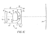
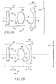
- a variable focal length zoom lens 10 includes a positive power first group 12 and a negative power second group 14.
- the first group 12 includes a first lens element 16 and a second lens element 18 with a variable iris 20 having a mechanical aperture positioned between the first lens element 16 and the second lens element 18.
- the second group includes a third lens element 22.
- the first group 12 and the second group 14 move relative to one another and move relative to and a curved image plane 24, often referred to as a film plane.
- the location of the first lens element 16 relative to the location of the second lens element is fixed within the first lens group 12. As such, the air gap between the first lens element 16 and the second lens element 18 does not change during zooming.
- the mechanical aperture of the variable iris 20 of the first lens group 12 changes depending on focal length and f/stop. However, light passing through the zoom lens 10 is not cut off or reduced by any other apertures as the zoom lens 10 experiences no vignetting.
- the first group 12 includes the first lens element 16 having surfaces S 1 and S 2 and the second lens element 18 having surfaces S 3 and S 4 .
- the overall power of the first group 12 is positive due primarily to the positive power of the spherical glass second lens element 18.
- the first lens element 16 is a substantially zero power plastic element having at least one aspherical surface (either S 1 or S 2 , or both S 1 and S 2 ) whose principal contribution to the zoom lens 10 is aberration correction which helps to maximize the performance of the zoom lens 10.
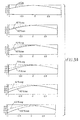
- the zoom lens 10 is highly corrected for the aberration of astigmatism.
- the zoom lens is highly corrected for spherical aberration at the wide angle and telephoto zoom positions.
- the third lens element 22 of the second group 14 includes a spherical, negative power glass element having surfaces S 5 and S 6 .
- the power of the first lens element 16 is held to a near neutral condition in order to reduce any image plane 24 position change due to the thermal reaction of the plastic first lens element 16 to environmental temperature changes which minimizes image quality degradation. Additionally, the weak positive power of the first lens element 16 of the first lens group 12 allows the first lens element 16 to be made from a polystyrene or polycarbonate material and still not contribute to a system focal length change due to a change in the temperature of the operating environment.
- the first lens element 16 is a meniscus lens having its concave surface facing the image plane 24. Details of the lens prescriptions for examples 1 through 3 are discussed below. Each of the examples 1 and 2 is designed with a unique curvature to the image plane 24 also listed below.
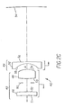
- a variable focal length zoom lens 40 includes a positive power first group 42 and a negative power second group 44.
- the first group 42 includes a first lens element 46 and a second lens element 48 with a variable iris 50 having a mechanical aperture positioned between the first lens element 46 and the second lens element 48.
- the second group 44 includes a third lens element 52.
- the first group 42 and the second group 44 move relative to one another and move relative to and a curved image plane 54, often referred to as a film plane.
- the location of the first lens element 46 relative to the location of the second lens element is fixed within the first lens group 42. As such, the air gap between the first lens element 46 and the second lens element 48 does not change during zooming.
- the mechanical aperture of the variable iris 50 of the first lens group 52 changes depending on focal length and f/stop. However, light passing through the zoom lens 40 is not cut off or reduced by any other apertures as the zoom lens 40 experiences no vignetting.
- the first group 42 includes the first lens element 46 having surfaces S 1 and S 2 and the second lens element 48 having surfaces S 3 and S 4 .
- the overall power of the first group 42 is positive due primarily to the positive power of the spherical glass second lens element 48.
- the first lens element 46 is a substantially zero power plastic element having at least one aspherical surface (either S 1 or S 2 , or both S 1 and S 2 ) whose principal contribution to the zoom lens 40 is aberration correction which helps to maximize the performance of the zoom lens 40.
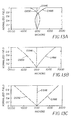
- the zoom lens 40 is highly corrected for the aberration of astigmatism.
- the zoom lens is highly corrected for spherical aberration at the wide angle and telephoto zoom positions.
- the third lens element 52 of the second group 44 includes a spherical, negative power glass element having surfaces S 5 and S 6 as viewed from a object side of the lens.
- the power of the first lens element 46 is held to a near neutral condition in order to reduce any image plane 54 position change due to the thermal reaction of the plastic first lens element 46 to environmental temperature changes. This minimizes image quality degradation. Additionally, the weak positive power of the first lens element 46 of the first lens group 42 allows the first lens element 46 to be made from a polystyrene or polycarbonate material and still not contribute to a system focal length change due to a change in the temperature of the operating environment.
- the first lens element 46 is a meniscus lens having its convex surface facing the image plane 54. Details of the lens prescription for example 4 are discussed below. Examples 3 and 4 is designed with a unique curvature to the image plane 54 also listed below.
- dimensions are in mm and indices and dispersions (V) are for the d line of the spectrum.
- the surfaces are numbered from the object side.
- image radii are for a cylindrical image (film) plane and the long dimension of image format is measured along a cylinder radius of curvature.
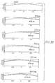
- the first lens element 16 has a focal length of 11,584.726
- the second lens element 18 has a focal length of 19.386,
- the third lens element 22 has a focal length of -20.192.
- the first group 12 has a focal length of 19.611.
- Example 1 has only one aspheric surface (S 1 ) which reduces tooling costs associated with manufacturing this lens element. Although its performance varies slightly (as measured by MTF), the zoom lens of Example 1 performs substantially similar to Examples 2-4, discussed below. Additionally, the zoom lens of Example 1 does not require on camera auto focus correction.
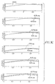
- the first lens element 16 has a focal length of -400.000
- the second lens element 18 has a focal length of 19.319
- the third lens element 22 has a focal length of -21.072.
- the first group 12 has a focal length of 19.650.
- Example 2 has two aspheric surfaces (S 1 and S 2 ) on the first lens element 16. Additionally, the zoom lens of Example 2 does not require on camera auto focus correction.
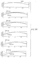
- the first lens element 46 has a focal length of 11,602.802
- the second lens element 48 has a focal length of 18.820
- the third lens element 52 has a focal length of-19.700.
- the first group 42 has a focal length of 19.523.
- Example 3 has two aspheric surfaces (S 1 and S 2 ) on the first lens element 46. Additionally, the zoom lens of Example 3 does not require on camera auto focus correction.
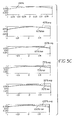
- the first lens element 46 has a focal length of 27,756.048
- the second lens element 48 has a focal length of 23.692
- the third lens element 52 has a focal length of -25.901.
- the first group 42 has a focal length of 23.423.
- Example 4 has two aspheric surfaces (S 1 and S 2 ) on the first lens element 46.
Landscapes
- Physics & Mathematics (AREA)
- General Physics & Mathematics (AREA)
- Optics & Photonics (AREA)
- Lenses (AREA)
Abstract
Description
| Surface | Radius | Thickness | Index | V |
| S1 | asphere | 3 | 1.590 | 30.9 |
| S2 | 94.58052 | 7.95 | ||
| STOP | diaphragm | 2.737 | ||
| S3 | 28.5354 | 8.5 | 1.516 | 64.1 |
| S4 | -13.93 | A | ||
| S5 | -10.7888 | 2 | 1.532 | 48.9 |
| S6 | infinity |
| Surface S1: | |||||||
| C = 0.01059276 | D = -0.3419951E-04 | F = -0.1222661E-07 | H = -0.3535696E-11 | ||||
| k = 0 | E = 0.2790696E-06 | G = 0.2959716E-09 | I = 0.1613439E-13 | ||||
| Focal Length |
Back Focus |
Front Focus |
Best Focus |
Zoom Spacing (A) |
Lens Length |
Stop Diameter |
Relative Aperture |
| 30.60 | 10.011 | 32.59 | -0.175 | 10.131 | 34.318 | 3.79 | 8.00 |
| 44.70 | 24.529 | 46.28 | -0.400 | 6.049 | 30.236 | 4.67 | 9.50 |
| 58.80 | 39.044 | 59.97 | 0.171 | 3.925 | 28.112 | 5.31 | 11.00 |
| Surface | Radius | Thickness | Index | V |
| S1 | asphere | 3.320 | 1.590 | 30.9 |
| S2 | asphere | 7.886 | ||
| STOP | diaphragm | 1.917 | ||
| S3 | 30.7474 | 8.5 | 1.517 | 64.2 |
| S4 | -13.4631 | A | ||
| S5 | -10.6706 | 1.6 | 1.532 | 48.8 |
| S6 | -214.880 |
| Surface S1: | |||||||
| C = 0.0027823 | D = -2.08203e-005 | F = 1.430412e-008 | H = 5.213367e-012 | ||||
| k = 0 | E = 2.536015e-007 | G = -4.306787e-010 | I = -2.407614e-014 | ||||
| Surface S2: | |||||||
| C = 0.0070085 | D = 1.989713e-005 | F = 5.116069e-008 | H = 3.321462e-011 | ||||
| k = 0 | E = 1.91235e-007 | G = -1.918757e-009 | I = -2.255516e-013 | ||||
| Focal Length |
Back Focus |
Front Focus |
Best Focus |
Zoom Spacing (A) |
Lens Length |
Stop Diameter |
Relative Aperture |
| 30.00 | 10.00 | 31.35 | -0.147 | 11.229 | 34.452 | 3.82 | 8.00 |
| 45.00 | 26.09 | 45.34 | -0.780 | 6.628 | 29.851 | 5.76 | 8.00 |
| 60.00 | 42.17 | 59.32 | 0.084 | 4.328 | 27.551 | 7.72 | 8.00 |
| Surface | Radius | Thickness | Index | V |
| S1 | asphere | 3.320 | 1.590 | 30.9 |
| S2 | asphere | 6.903 | ||
| STOP | diaphragm | 1.97 | ||
| S3 | 31.922 | 8.5 | 1.516 | 64.1 |
| S4 | -12.7685 | A | ||
| S5 | -10.2526 | 2.12 | 1.532 | 48.9 |
| S6 | -423.736 |
| Surface S1: | |||||||
| C = -0.0125646 | D = -3.089281e-005 | F = -1.899357e-009 | H = 0 | ||||
| k = 0 | E = 7.189489e-007 | G = -1.72253e-011 | I = 0 | ||||
| Surface S2: | |||||||
| C = -0.0125148 | D = 1.499608e-005 | F = 6.170526e-009 | H = 0 | ||||
| k = 0 | E = 8.161403e-007 | G = -1.572474e-010 | I = 0 | ||||
| Focal Length |
Back Focus |
Front Focus |
Best Focus |
Zoom Spacing (A) |
Lens Length |
Stop Diameter |
Relative Aperture |
| 28.56 | 9.256 | 30.30 | -0.151 | 10.191 | 33.004 | 3.63 | 8.00 |
| 41.72 | 23.256 | 42.68 | -0.378 | 6.160 | 28.973 | 4.48 | 9.50 |
| 54.88 | 37.251 | 55.05 | 0.050 | 4.063 | 26.876 | 5.09 | 11.00 |
| Surface | Radius | Thickness | Index | V |
| S1 | asphere | 3.320 | 1.590 | 30.9 |
| S2 | asphere | 7.950 | ||
| STOP | diaphragm | 3.728 | ||
| S3 | 46.1515 | 8.261 | 1.516 | 64.1 |
| S4 | -15.7064 | A | ||
| S5 | -12.9723 | 1.618 | 1.532 | 48.9 |
| S6 | -216.148 |
| Surface S1: | |||||||
| C = -0.0090436 | D = -2.12562e-005 | F = 5.597426e-009 | H = 2.185771e-012 | ||||
| k = 0 | E = 4.122822e-007 | G = -1.732179e-010 | I = -1.314e-014 | ||||
| Surface S2: | |||||||
| C=-0.0090034 | D=4.282486e-006 | F=4.125799e-009 | H=-7.224068e-012 | ||||
| k=0 | E=5.55882e-007 | G=1.755683e-010 | I=4.904076e-014 | ||||
| Focal Length |
Back Focus |
Front Focus |
Best Focus |
Zoom Spacing (A) |
Lens Length |
Stop Diameter |
Relative Aperture |
| 35.70 | 12.45 | 37.81 | -0.184 | 13.384 | 38.261 | 4.52 | 8.00 |
| 52.15 | 30.65 | 52.69 | -0.584 | 8.023 | 32.900 | 5.89 | 9.00 |
| 68.60 | 48.83 | 67.56 | 0.059 | 5.234 | 30.111 | 6.34 | 11.00 |
Claims (9)
- A zoom lens comprising, in order from an object side:a first lens group having a first lens element and a second lens element; anda second lens group having a third lens element, wherein the zoom lens satisfies the following condition: |1|/w < 0.003, where 1 is a power of the first lens element and w is a power of the zoom lens in a wide angle position.
- The zoom lens according to Claim 1, wherein at least one surface of the first lens element is aspherical.
- The zoom lens according to Claim 2, wherein the first lens element is a plastic element.
- The zoom lens according to Claim 1, wherein the first lens element is a meniscus lens having a concave surface on the object side.
- The zoom lens according to Claim 1, wherein the first lens element is a meniscus lens having a convex surface on the object side.
- The zoom lens according to Claim 1, wherein the second lens element is a spherical glass element.
- The zoom lens according to Claim 1, wherein the third lens element is a spherical glass element.
- The zoom lens according to Claim 1, wherein the first lens group includes a variable iris having a mechanical aperture stop positioned between the first lens element and the second lens element.
- The zoom lens according to Claim 1, wherein the first lens element is in a fixed position relative to the second lens element and moveably positioned relative to the third lens element.
Applications Claiming Priority (2)
| Application Number | Priority Date | Filing Date | Title |
|---|---|---|---|
| US09/885,572 US6525886B1 (en) | 2001-06-20 | 2001-06-20 | Two group zoom lens having weak front element |
| US885572 | 2001-06-20 |
Publications (2)
| Publication Number | Publication Date |
|---|---|
| EP1271216A2 true EP1271216A2 (en) | 2003-01-02 |
| EP1271216A3 EP1271216A3 (en) | 2004-11-03 |
Family
ID=25387217
Family Applications (1)
| Application Number | Title | Priority Date | Filing Date |
|---|---|---|---|
| EP02077240A Withdrawn EP1271216A3 (en) | 2001-06-20 | 2002-06-10 | Two group zoom lens having weak front element |
Country Status (3)
| Country | Link |
|---|---|
| US (1) | US6525886B1 (en) |
| EP (1) | EP1271216A3 (en) |
| JP (1) | JP2003043355A (en) |
Cited By (1)
| Publication number | Priority date | Publication date | Assignee | Title |
|---|---|---|---|---|
| EP1724622A3 (en) * | 2003-07-11 | 2007-06-27 | Konica Minolta Opto, Inc. | Image pick-up lens, image pick-up unit, and mobile terminal provided with this image pick-up unit |
Families Citing this family (10)
| Publication number | Priority date | Publication date | Assignee | Title |
|---|---|---|---|---|
| JP2002300480A (en) * | 2001-03-29 | 2002-10-11 | Fuji Photo Optical Co Ltd | Electronic camera |
| WO2005047952A1 (en) | 2003-11-17 | 2005-05-26 | Olympus Corporation | A variable-power optical system and electronic device using same |
| JP2007114727A (en) * | 2005-09-26 | 2007-05-10 | Konica Minolta Opto Inc | Zoom lens |
| CN101571621B (en) * | 2008-04-28 | 2011-03-23 | 鸿富锦精密工业(深圳)有限公司 | Imaging lens |
| WO2014043142A1 (en) | 2012-09-11 | 2014-03-20 | Augmented Vision, Inc. | Compact eye imaging and eye tracking apparatus |
| WO2017068637A1 (en) | 2015-10-20 | 2017-04-27 | オリンパス株式会社 | Imaging device and optical apparatus provided therewith |
| CN106896482B (en) * | 2017-04-24 | 2022-03-29 | 浙江舜宇光学有限公司 | Iris lens |
| CN120276136A (en) * | 2021-09-02 | 2025-07-08 | 三星电机株式会社 | Optical system |
| CN115166936B (en) * | 2022-06-28 | 2023-11-07 | 江西晶超光学有限公司 | Optical systems, lens modules and electronic equipment |
| CN120891625B (en) * | 2025-09-29 | 2026-01-30 | 浙江舜宇光学有限公司 | Optical imaging lens |
Family Cites Families (9)
| Publication number | Priority date | Publication date | Assignee | Title |
|---|---|---|---|---|
| US5329401A (en) * | 1991-01-11 | 1994-07-12 | Nikon Corporation | Super wide angle zoom lens |
| JP3314786B2 (en) * | 1991-10-22 | 2002-08-12 | オリンパス光学工業株式会社 | Zoom lens using plastic |
| US5270867A (en) | 1991-12-13 | 1993-12-14 | Eastman Kodak Company | Compact zoom lens having a weak front lens group |
| US5270861A (en) * | 1991-12-13 | 1993-12-14 | Eastman Kodak Company | Zoom lens system for use in a compact camera |
| KR0124951B1 (en) * | 1993-11-11 | 1997-12-05 | 이대원 | Zoom lens |
| US5473473A (en) | 1993-12-20 | 1995-12-05 | Eastman Kodak Company | Two element plastic zoom camera lens |
| JP3366092B2 (en) * | 1993-12-24 | 2003-01-14 | オリンパス光学工業株式会社 | High zoom ratio 2-group zoom lens |
| US5604639A (en) | 1994-12-30 | 1997-02-18 | Eastman Kodak Company | Two-element optical system and camera and method of making a camera |
| US5815324A (en) * | 1995-09-19 | 1998-09-29 | Minolta Co., Ltd. | Zoom lens system for a lens shutter camera |
-
2001
- 2001-06-20 US US09/885,572 patent/US6525886B1/en not_active Expired - Lifetime
-
2002
- 2002-06-10 EP EP02077240A patent/EP1271216A3/en not_active Withdrawn
- 2002-06-19 JP JP2002178578A patent/JP2003043355A/en active Pending
Cited By (2)
| Publication number | Priority date | Publication date | Assignee | Title |
|---|---|---|---|---|
| EP1724622A3 (en) * | 2003-07-11 | 2007-06-27 | Konica Minolta Opto, Inc. | Image pick-up lens, image pick-up unit, and mobile terminal provided with this image pick-up unit |
| US7420609B2 (en) | 2003-07-11 | 2008-09-02 | Konica Minolta Opto, Inc. | Image pick-up lens, image pick-up unit, and mobile terminal provided with this image pick-up unit |
Also Published As
| Publication number | Publication date |
|---|---|
| US6525886B1 (en) | 2003-02-25 |
| JP2003043355A (en) | 2003-02-13 |
| EP1271216A3 (en) | 2004-11-03 |
Similar Documents
| Publication | Publication Date | Title |
|---|---|---|
| US6025962A (en) | Zoom lens with an anti-vibration function | |
| US7663814B2 (en) | Imaging lens system and imaging apparatus | |
| JP3573575B2 (en) | Optical system | |
| CN113467046B (en) | Optical lens, camera module and detector | |
| US8027099B2 (en) | Optical system for camera | |
| CN109633870B (en) | Optical lens and imaging apparatus | |
| US5940219A (en) | Imaging lens | |
| US7046454B2 (en) | Two-group zoom lens | |
| CN113156611A (en) | Optical lens and imaging apparatus | |
| CN110275274B (en) | Optical imaging system | |
| CN114488473A (en) | Optical system, lens module and electronic equipment | |
| EP1271216A2 (en) | Two group zoom lens having weak front element | |
| US6600610B2 (en) | Standard photographic lens | |
| US20050078380A1 (en) | Two-group zoom lens | |
| JP5247307B2 (en) | Wide-angle lens and imaging module | |
| CN110941073A (en) | Optical imaging module | |
| US6917477B2 (en) | Two-group zoom lens | |
| EP1115020A2 (en) | Front tele-converter, and front tele-converter having vibration-reduction function | |
| CN111965795B (en) | Imaging optical system | |
| CN113296251B (en) | Zoom lens and imaging device | |
| TWI804795B (en) | Optical lens and fabrication method thereof | |
| US6995923B2 (en) | Small lightweight zoom lens | |
| US4747676A (en) | Wide-angle seven-element lens system | |
| US8199413B2 (en) | Compact zoom optical system | |
| US11650487B2 (en) | Front converter optical assembly for camera |
Legal Events
| Date | Code | Title | Description |
|---|---|---|---|
| PUAI | Public reference made under article 153(3) epc to a published international application that has entered the european phase |
Free format text: ORIGINAL CODE: 0009012 |
|
| AK | Designated contracting states |
Kind code of ref document: A2 Designated state(s): AT BE CH CY DE DK ES FI FR GB GR IE IT LI LU MC NL PT SE TR |
|
| AX | Request for extension of the european patent |
Free format text: AL;LT;LV;MK;RO;SI |
|
| PUAL | Search report despatched |
Free format text: ORIGINAL CODE: 0009013 |
|
| AK | Designated contracting states |
Kind code of ref document: A3 Designated state(s): AT BE CH CY DE DK ES FI FR GB GR IE IT LI LU MC NL PT SE TR |
|
| AX | Request for extension of the european patent |
Extension state: AL LT LV MK RO SI |
|
| AKX | Designation fees paid | ||
| REG | Reference to a national code |
Ref country code: DE Ref legal event code: 8566 |
|
| STAA | Information on the status of an ep patent application or granted ep patent |
Free format text: STATUS: THE APPLICATION IS DEEMED TO BE WITHDRAWN |
|
| 18D | Application deemed to be withdrawn |
Effective date: 20050504 |