EP1271213A2 - Tape-based, high fiber-count cable - Google Patents
Tape-based, high fiber-count cable Download PDFInfo
- Publication number
- EP1271213A2 EP1271213A2 EP02291493A EP02291493A EP1271213A2 EP 1271213 A2 EP1271213 A2 EP 1271213A2 EP 02291493 A EP02291493 A EP 02291493A EP 02291493 A EP02291493 A EP 02291493A EP 1271213 A2 EP1271213 A2 EP 1271213A2
- Authority
- EP
- European Patent Office
- Prior art keywords
- optical fiber
- composite tape
- stacks
- buffer
- fiber cable
- Prior art date
- Legal status (The legal status is an assumption and is not a legal conclusion. Google has not performed a legal analysis and makes no representation as to the accuracy of the status listed.)
- Granted
Links
Images



Classifications
-
- G—PHYSICS
- G02—OPTICS
- G02B—OPTICAL ELEMENTS, SYSTEMS OR APPARATUS
- G02B6/00—Light guides; Structural details of arrangements comprising light guides and other optical elements, e.g. couplings
- G02B6/44—Mechanical structures for providing tensile strength and external protection for fibres, e.g. optical transmission cables
- G02B6/4401—Optical cables
- G02B6/441—Optical cables built up from sub-bundles
Definitions
- the present invention generally relates to the field of fiber optic cables, in particular the present invention is directed to a new and novel method and apparatus for supporting and packaging optical fibers.
- Optical fibers are very small diameter glass strands which are capable of transmitting an optical signal over great distances, at very high speeds, and with relatively low signal loss as compared to standard wire or cable networks.
- Optical fibers are used in many areas of technology, and because of this development, there is a growing need to have fiber optic cable configurations which can provide adequate support for the optical fibers, and which are sized so that they can be effectively used in various environments.
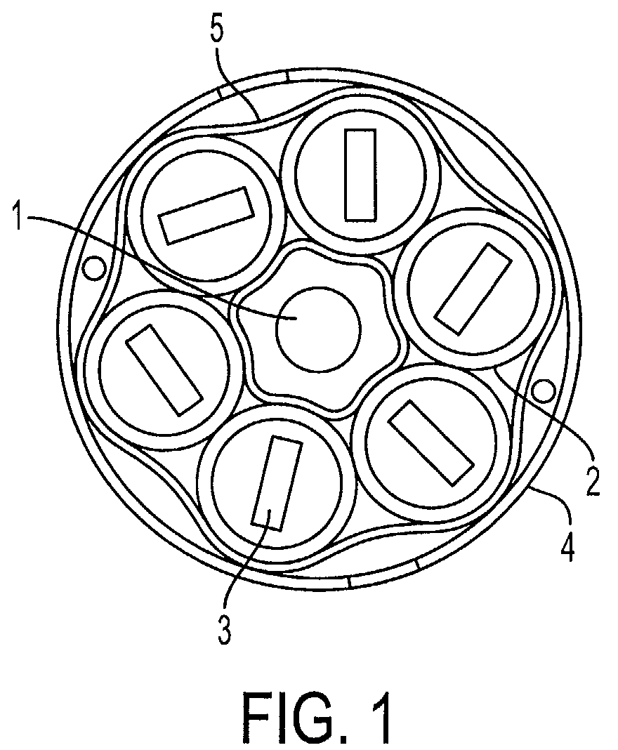
- FIG. 1 An example of a common fiber optic cable cross-section can be seen in Figure 1.
- the central strength member 1 can be made from a number of different materials, such as hard plastic, glass, or a glass reinforced composite and is used as a load bearing member for the cable, as well as for supporting the inner sides of buffer tubes 2 that are typically stranded around the central strength member in a helical path.
- Figure 1 shows six buffer tubes 2, the quantity can increase or decrease depending on the particular application the cable is to be used for.
- Each buffer tube 2 is a plurality of individual optical fibers 3.
- the optical fibers 3 can be configured in any number of ways.
- each buffer tube 2 there can be a stacked ribbon configuration (as shown in Figure 1) where each ribbon has a plurality of individual fibers and there are a number of ribbons.
- the fibers 3 can be configured as bundles inside the buffer tube. The configuration will greatly depend on the use and application of the cable.
- the outer jacket 4 provides protection to the internal components of the cable, while aiding to keep all of the components together. The outer jacket 4 provides protection from the adverse physical elements that a cable can be exposed to during its use and installation.
- the present invention is directed to eliminating the above problems associated with the use of various thermoplastics and multiple components, to form optical fiber configurations.
- the invention improves the quality of the optical fiber cable while reducing the cross-section size, number of components and weight.
- the present invention addresses the above problems by providing an optical fiber configuration and method.
- the optical fiber configuration comprises fibers that are grouped by buffer tubes using a lightweight fabric-type composite tape material to serve as a strength member.
- the configuration is manufactured by first providing a plurality of optical fibers upon the composite tape material. Gel or foamy glue is placed on the tape and is used as a filler and an adhesive to secure the optical fibers to the tape.
- a buffer tube is then formed by rolling the composite tape or helically wrapping the tape around the fibers such that the tape takes on a tube shape and surrounds the fibers.
- multiple buffer tubes may be bundled together to form a stack. This is done by providing an additional piece of composite material having gel on one side, and placing the buffer tubes on the gel side of the composite tape material.
- the stack is then formed by rolling the tape to enclose the buffer tubes while excess gel serves to fill in gaps. Multiple stacks may then be stranded to form a larger cable that uses another piece of composite tape material along with an additional rolling process, similar to that described above.
- the individual stacks may be formed to have a triangular or trapezoidal shape for efficient packaging.
- the present invention provides an optical cable configuration with improved quality while reducing the cross-section size, number of components and weight.
- the configuration employs innovative geometry and cost-effective materials for both dielectric and armored optical fiber cables.
- the tape provides a way of supporting and manipulating the optical fibers without extensive reliance on extruded plastic tubes or additional strength members, resulting in a reduced diameter.
- the fibers can be grouped into traditional buffer tubes or cell structures for easy identification. Additionally, with the increased number of fibers, a self-supporting effect is created that permits the fibers to carry an increased amount of external load, which further reduces excessive reliance on expensive and space-consuming strength members.
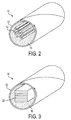
- a wound piece of composite tape 12 is provided to form a tubular shaped element or buffer tube 10.
- the composite tape 12 serves as a strength member to contain optical fibers 14.
- the optical fibers 14 are positioned in the buffer tube 10 according to the method described below.
- a gel or foamy glue 16 may be provided within the buffer tube 10 for filling the air gaps and positioning the optical fibers 14.
- the buffer tube 10 formed from the composite tape 12 according to the present invention acts to support and protect the fibers from external forces.
- the composite tape can be of the type known in the art, and which has adequate tensile and compression strength properties.
- the composite by way of example, can be made by combining fibers of an organic mesh-type substrate with inorganic dot-type ceramic materials for fire protection (such as Nextel 3M Flame Stopping Dot Paper).
- the color of the composite tape may vary to allow for easy identification of the fibers in color-coded buffer cells.
- a buffer tube 18 may also be formed to contain optical fiber ribbons 20.
- the optical fiber ribbons 20 allow for an increase in fiber packing density within the given space created by the rolled composite tape 12. This is advantageous as higher packing densities allow for more fiber to be placed in a given diameter cable and thus more efficient use of existing cable ducts. Further, use of the optical fiber ribbons 20 provide easier fiber identification, maintenance and splicing when working on the fibers.
- the size of the optical fiber ribbons 20 may be varied depending on the particular application.
- a gel or foamy glue 16 may be provided within the buffer tube 18 for filling the air gaps and positioning the optical fibers ribbons 20.
- the optical fibers 14 or the optical fiber ribbons 20 may also be advantageous to provide the optical fibers 14 or the optical fiber ribbons 20 on an outside portion of the rolled composite tape 12, such that the composite tape 12 is rolled to form a tube and optical fiber ribbons 18 are positioned radially on the outside portion of the rolled composite tape 12.
- This configuration provides particular benefits because stacks of ribbons are positioned on top of a light-weight cylinder made of a composite material. The cylinder is empty, thus the cable weight is reduced.
- traditional thermoplastic or a new composite-tape layer can be used as an outer jacket to enclose the stacks of ribbons.
- the cavity of the hollow central tube can be used to run electric wires, or other elements typically found in hybrid telecommunication and power cables.
- Another benefit of this embodiment is that, when under radial compression, the hollow central tube does not embed into the ribbons, but rather deforms, and protects the fibers from excessive stress.
- Figure 4 shows a stack 22 of buffer tubes 18 containing optical fiber ribbons 20.
- the stack 22 is bundled together by a piece of wound composite tape 24 that forms an outer jacket.
- the composite tape 24 serves as a strength and support member for the stack 22. Due to the physical attributes of the composite tape 24, it is possible to form the stack 22 to take on varies geometrical shapes. For example, as shown in Figure 4, the stack 22 may be formed to have a triangular shape.
- a gel or foamy glue 26 may be used to fill in gaps between the buffer tubes 18 and to hold the stack 22 together.
- suitable gel formulations include gels comprised of mineral oils and/or synthetic polyolefin oils combined with a polymeric thixotropy modifier or pyrogenic silica.
- Commercially available gel compounds include Mastergel R-1806 and R-1806LT.
- Figure 4 shows buffer tubes 18 containing optical fiber ribbons 20, it will be appreciated that various configurations of optical fibers can be used within the buffer tubes.
- an optical fiber cable configuration 28 is formed with a plurality of sub-units or stacks 22 containing a plurality of buffer tubes 18 with optical fibers.
- the optical fiber configuration 28 includes an additional piece of wound composite tape 30 that serves as a strength member to form an outer protective sheath, and which bundles together a plurality of stacks 22.
- the stacks 22 may take on a variety of shapes.
- the stacks 22 are formed to have a triangular or trapezoidal shape that allows for them to be disposed radially inside of the wound piece of composite tape 30 in a space-efficient manner similar to pie charts.
- the space between adjacent stacks 22 of the optical fiber configuration 28 may be filled in with a gel 32, which acts to reduce water penetration along the cable length, to hold the stacks 22 in place and increases the overall stability of the optical fiber configuration. It will be appreciated that the number of stacks 22 that can be positioned within the outer protective sheath 30 is dependent on the forming of the stacks 22 to have a shape which minimizes areas between adjacent stacks 22.
- the optical fiber configuration 28 may also have an axial member 34 that is centrally positioned with respect to the outer protective sheath 30.
- the axial member 34 is used to provide further support to the optical fiber configuration 28, and can be used to hold and support additional optical fibers or other elongated elements such as electric power wire or power cable.
- the axial member may be formed from rolled composite tape, as described above with respect to the buffer tubes 10 and 18, and contain optical fibers 14, which may take the form of optical fiber ribbons 20.
- the composite tape 12 is positioned in an unrolled condition.
- a gel or foamy type glue 38 is applied to an open face 36 of the composite tape 12.
- Optical fibers are then positioned on the composite tape 12.
- Figure 6 shows the optical fibers in the optical fiber ribbon configuration 20, as discussed above with reference to Figure 3; however, various configurations of optical fibers may be used.
- the composite tape 12 is rolled or wrapped around the fibers so that a buffer tube 18 configuration is formed.
- a similar rolling process is then performed to form the stacks 22, and then to form the optical fiber configuration that is described with reference to Figure 5.
- the tape can be helically wrapped, or may be applied longitudinally.
- the tape is described as being a composite tape, it will be appreciated that any tape having sufficient strength may be used.
- buffer tubes buffer cells, stacks and an outer protective sheath which are described as being formed from a wound piece of composite tape
- one or more of these supportive members may be formed from the traditional thermoplastic materials.
- optical fiber unit shown in Figure 5 can also be stranded around a common central strength member for example, helically, to form, for example a super-unit cable containing multiple units to form a cable having a larger number of optical fibers.
Landscapes
- Physics & Mathematics (AREA)
- General Physics & Mathematics (AREA)
- Optics & Photonics (AREA)
- Communication Cables (AREA)
- Insulated Conductors (AREA)
- Ropes Or Cables (AREA)
- Optical Fibers, Optical Fiber Cores, And Optical Fiber Bundles (AREA)
- Decoration Of Textiles (AREA)
Abstract
Description
Claims (19)
- An optical fiber cable configuration, comprising:an outer protective sheath formed from a piece of wound composite tape;a plurality of stacks which are stranded to be radially positioned within said outer protective sheath, wherein each of said plurality of stacks includes a plurality of buffer tubes.
- The optical fiber cable configuration of claim 1, wherein each of said plurality of stacks is formed to have one of a triangular and trapezoidal shape.
- The optical fiber cable configuration of claim 1, wherein said buffer tubes each contain at least one optical fiber.
- The optical fiber cable configuration of claim 1, wherein said buffer tubes each contain at least one optical fiber ribbon.
- The optical fiber cable configuration of claim 1, wherein said plurality of stacks each have an outer portion formed from a wound piece of composite tape, which respectively supports said plurality of buffer tubes within each of said stacks.
- The optical fiber cable configuration of claim 3, wherein each of said buffer tubes has an outer portion formed from a wound piece of composite tape, which supports said optical fiber contained in said buffer tube.
- The optical fiber cable configuration of claim 4, wherein each of said buffer tubes has an outer portion formed from a wound piece of composite tape, which supports said optical fiber ribbon contained in said buffer tube.
- The optical fiber cable configuration of claim 6, wherein said at least one optical fiber is surrounded with gel.
- The optical fiber cable configuration of claim 7, wherein said optical fiber is surrounded with gel.
- The optical fiber cable configuration of claim 1, further comprising an axial member which is centrally positioned with respect to said outer protective sheath, and is formed from a wound piece of composite tape.
- An optical fiber cable configuration, comprising:a first buffer tube formed from a piece of wound composite tape; andat least one optical fiber disposed in said first buffer tube.
- The optical fiber cable configuration of claim 11, further comprising at least one second buffer tube formed from a piece of wound composite tape and positioned contiguous to said first buffer tube;at least one optical fiber disposed in said at least one second buffer tube; andan outer jacket surrounding said first and second buffer tubes to form a first stack.
- The optical fiber cable configuration of claim 12, wherein said outer jacket is formed from a piece of wound composite tape.
- The optical fiber cable configuration of claim 13, further comprising a protective sheath which contains said first stack and a second stack, and wherein said first and second stacks are formed to have a triangular shape, such that said stacks are in a radial arrangement with respect to a center of said protective sheath.
- The optical fiber cable configuration of claim 14, wherein said protective sheath is formed from a wound piece of composite tape.
- An optical fiber cable configuration, comprising:outer protective sheath;a plurality of stacks which are stranded to be radially positioned within said outer protective sheath, wherein each of said plurality of stacks includes a plurality of buffer tubes which contain an optical fiber and each of said plurality of stacks is formed to have a triangular shape, wherein at least one of said outer protective sheath, said stacks, and said plurality of buffer tubes, has an outer support portion which is formed from a wound piece of composite tape.
- A method of making an optical fiber configuration, comprising:providing a piece of composite tape;applying gel to a first side of said composite tape;depositing an optical fiber on said composite tape;rolling said composite tape to form a buffer tube so that said optical fiber is contained within said buffer tube, wherein said composite tape provides support to said optical fiber.
- The method of making an optical fiber configuration of claim 17, further comprising:bundling a plurality of said buffer tubes with a composite tape to form a stack having a triangular shape; andpositioning, radially, a plurality of stacks within an outer protective sheath formed from a wound piece of composite tape.
- The method of making an optical fiber configuration of claim 17, wherein said rolling is done helically.
Applications Claiming Priority (2)
| Application Number | Priority Date | Filing Date | Title |
|---|---|---|---|
| US09/883,998 US6760523B2 (en) | 2001-06-20 | 2001-06-20 | Tape based high fiber count cable |
| US883998 | 2001-06-20 |
Related Child Applications (1)
| Application Number | Title | Priority Date | Filing Date |
|---|---|---|---|
| EP09002397 Division | 2009-02-20 |
Publications (3)
| Publication Number | Publication Date |
|---|---|
| EP1271213A2 true EP1271213A2 (en) | 2003-01-02 |
| EP1271213A3 EP1271213A3 (en) | 2005-07-27 |
| EP1271213B1 EP1271213B1 (en) | 2009-08-26 |
Family
ID=25383761
Family Applications (1)
| Application Number | Title | Priority Date | Filing Date |
|---|---|---|---|
| EP02291493A Expired - Lifetime EP1271213B1 (en) | 2001-06-20 | 2002-06-14 | Tape-based, high fiber-count cable |
Country Status (5)
| Country | Link |
|---|---|
| US (1) | US6760523B2 (en) |
| EP (1) | EP1271213B1 (en) |
| CN (1) | CN1170181C (en) |
| AT (1) | ATE441127T1 (en) |
| DE (1) | DE60233459D1 (en) |
Cited By (4)
| Publication number | Priority date | Publication date | Assignee | Title |
|---|---|---|---|---|
| WO2004073507A1 (en) * | 2003-02-18 | 2004-09-02 | Karl Storz Gmbh & Co. Kg | Method for assembling an endoscope |
| WO2006016104A1 (en) * | 2004-08-12 | 2006-02-16 | Emtelle Uk Limited | Tube bundle for optical fibres, and method of manufacturing such bundle |
| CN100465683C (en) * | 2004-08-12 | 2009-03-04 | 艾姆特利英国有限公司 | Tube bundle for optical fibers and method of manufacturing such tube bundle |
| WO2015047896A3 (en) * | 2013-09-27 | 2015-05-21 | Corning Optical Communications LLC | Optical communication cable |
Families Citing this family (29)
| Publication number | Priority date | Publication date | Assignee | Title |
|---|---|---|---|---|
| US20040076387A1 (en) * | 2002-10-17 | 2004-04-22 | Alcatel | Fiber optic tube and method of forming a fiber optic tube from a tape |
| US6912347B2 (en) * | 2002-11-15 | 2005-06-28 | Alcatel | Optimized fiber optic cable suitable for microduct blown installation |
| US7298946B2 (en) * | 2004-12-22 | 2007-11-20 | Hewlett-Packard Development Company, L.P. | Multi-fiber cable for efficient manageability of optical system |
| DE102005001670B3 (en) * | 2005-01-13 | 2006-08-24 | CCS Technology, Inc., Wilmington | Fire-resistant cable and method of making such a cable |
| US7225534B2 (en) * | 2005-02-11 | 2007-06-05 | Adc Telecommunications, Inc. | Telecommunications cable jacket adapted for post-extrusion insertion of optical fiber and methods for manufacturing the same |
| US7158712B2 (en) * | 2005-05-06 | 2007-01-02 | Coretech Optical Co., Ltd. | Optical fiber coupler and manufacturing apparatus and method thereof |
| US7515795B2 (en) * | 2005-07-20 | 2009-04-07 | Draka Comteq B.V. | Water-swellable tape, adhesive-backed for coupling when used inside a buffer tube |
| US7567739B2 (en) * | 2007-01-31 | 2009-07-28 | Draka Comteq B.V. | Fiber optic cable having a water-swellable element |
| US7599589B2 (en) * | 2005-07-20 | 2009-10-06 | Draka Comteq B.V. | Gel-free buffer tube with adhesively coupled optical element |
| US7577329B2 (en) * | 2007-03-14 | 2009-08-18 | Superior Essex Communications Lp | Data communication cable comprising filling matrix and method of fabrication |
| CN101382628A (en) * | 2008-10-06 | 2009-03-11 | 沈群华 | Improved fiber ribbon and optical cable using the fiber ribbon |
| US8682123B2 (en) | 2010-07-15 | 2014-03-25 | Draka Comteq, B.V. | Adhesively coupled optical fibers and enclosing tape |
| US9170388B2 (en) * | 2011-09-30 | 2015-10-27 | Corning Cable Systems Llc | Fiber optic ribbon cable having enhanced ribbon stack coupling and methods thereof |
| US11287589B2 (en) | 2012-09-26 | 2022-03-29 | Corning Optical Communications LLC | Binder film for a fiber optic cable |
| US8620124B1 (en) | 2012-09-26 | 2013-12-31 | Corning Cable Systems Llc | Binder film for a fiber optic cable |
| CN103529509B (en) * | 2013-03-07 | 2017-02-15 | 上海飞凯光电材料股份有限公司 | Optical fiber and manufacturing method and identifying method of optical fiber |
| US11187862B2 (en) | 2013-03-28 | 2021-11-30 | Corning Optical Communications LLC | Coupling system for fiber optic cable using raised tape |
| US9581777B2 (en) | 2013-03-28 | 2017-02-28 | Corning Optical Communications LLC | Coupling system for fiber optic cable using folded tape |
| US9482839B2 (en) | 2013-08-09 | 2016-11-01 | Corning Cable Systems Llc | Optical fiber cable with anti-split feature |
| US9075212B2 (en) | 2013-09-24 | 2015-07-07 | Corning Optical Communications LLC | Stretchable fiber optic cable |
| US8805144B1 (en) | 2013-09-24 | 2014-08-12 | Corning Optical Communications LLC | Stretchable fiber optic cable |
| US9594226B2 (en) | 2013-10-18 | 2017-03-14 | Corning Optical Communications LLC | Optical fiber cable with reinforcement |
| US9389382B2 (en) | 2014-06-03 | 2016-07-12 | Corning Optical Communications LLC | Fiber optic ribbon cable and ribbon |
| GB2543676B (en) | 2014-08-15 | 2019-04-10 | Halliburton Energy Services Inc | Enhanced radial support for wireline and slickline |
| CN106646796A (en) * | 2016-11-24 | 2017-05-10 | 北京亨通斯博通讯科技有限公司 | Triangular cross section drop optical cable and manufacturing method thereof |
| CN107767995B (en) * | 2017-09-23 | 2023-10-03 | 立讯精密工业股份有限公司 | round cable |
| JP7192782B2 (en) * | 2017-11-02 | 2022-12-20 | 住友電気工業株式会社 | Optical fiber unit and optical fiber cable |
| JP2021043327A (en) * | 2019-09-11 | 2021-03-18 | 住友電気工業株式会社 | Fiber optic unit and fiber optic cable |
| CN114594558A (en) * | 2022-04-01 | 2022-06-07 | 祁源 | Optical fiber ribbon optical cable with internal winding structure |
Family Cites Families (19)
| Publication number | Priority date | Publication date | Assignee | Title |
|---|---|---|---|---|
| US4146302A (en) | 1975-06-02 | 1979-03-27 | General Cable Corporation | Construction of cable made of optical fibres |
| US4468089A (en) | 1982-07-09 | 1984-08-28 | Gk Technologies, Inc. | Flat cable of assembled modules and method of manufacture |
| US4952020A (en) | 1989-08-09 | 1990-08-28 | Amp Incorporated | Ribbon cable with optical fibers and electrical conductors |
| GB2247340B (en) * | 1990-08-24 | 1994-06-15 | Stc Plc | Limited fire hazard cable |
| US5212756A (en) | 1992-01-21 | 1993-05-18 | Siecor Corporation | Fiber optic ribbon cable including flexible web |
| US5166998A (en) | 1992-02-21 | 1992-11-24 | Siecor Corporation | Optical ribbon cable component |
| DE4312121B4 (en) | 1993-04-14 | 2004-04-15 | CCS Technology, Inc., Wilmington | Optical cable with several optical fibers arranged in a given structure |
| US5440665A (en) | 1993-04-16 | 1995-08-08 | Raychem Corporation | Fiber optic cable system including main and drop cables and associated fabrication method |
| US5343549A (en) * | 1993-08-25 | 1994-08-30 | Siecor Corporation | Riser optical cable having filling compound |
| FR2727212B1 (en) | 1994-11-21 | 1997-01-03 | Alcatel Cable | METHOD FOR MANUFACTURING A CYLINDRICAL FIBER OPTIC MODULE |
| FR2732120B1 (en) * | 1995-03-24 | 1997-04-30 | Alcatel Cable | OPTICAL FIBER CABLE |
| US5933559A (en) | 1996-07-22 | 1999-08-03 | Dsm N.V. | Radiation-curable cross-linked ribbon matrix material for bonding an array of coated optical glass fibers |
| US6085010A (en) | 1997-06-11 | 2000-07-04 | Dsm N.V. | Optical glass fiber ribbon assemblies and radiation-curable compositions for use in forming ribbon assemblies |
| US5917977A (en) | 1997-09-16 | 1999-06-29 | Siecor Corporation | Composite cable |
| US6304701B1 (en) * | 1998-03-27 | 2001-10-16 | Corning Cable Systems Llc | Dry fiber optic cable |
| US6195486B1 (en) * | 1998-06-02 | 2001-02-27 | Siecor Operations, Llc | Fiber optic cable having a component with an absorptive polymer coating and a method of making the cable |
| GB2343014A (en) * | 1998-10-23 | 2000-04-26 | Bowthorpe Plc | Optic fibre cable |
| US6215932B1 (en) * | 1999-09-15 | 2001-04-10 | Lucent Technologies Inc. | Stacks of optical fiber ribbons closely bound by respective buffer encasements with relatively hard exteriors and relatively soft interiors, associated methods, and associated fiber optic cables |
| US6321013B1 (en) * | 1999-09-15 | 2001-11-20 | Lucent Technologies, Inc. | Stacks of optical fiber ribbons closely bound by respective buffer encasements, associated methods, and associated fiber optic cables |
-
2001
- 2001-06-20 US US09/883,998 patent/US6760523B2/en not_active Expired - Fee Related
-
2002
- 2002-06-07 CN CNB021227209A patent/CN1170181C/en not_active Expired - Fee Related
- 2002-06-14 DE DE60233459T patent/DE60233459D1/en not_active Expired - Fee Related
- 2002-06-14 EP EP02291493A patent/EP1271213B1/en not_active Expired - Lifetime
- 2002-06-14 AT AT02291493T patent/ATE441127T1/en not_active IP Right Cessation
Cited By (9)
| Publication number | Priority date | Publication date | Assignee | Title |
|---|---|---|---|---|
| WO2004073507A1 (en) * | 2003-02-18 | 2004-09-02 | Karl Storz Gmbh & Co. Kg | Method for assembling an endoscope |
| US7662096B2 (en) | 2003-02-18 | 2010-02-16 | Karl Storz Gmbh & Co. Kg | Method for assembling an endoscope |
| WO2006016104A1 (en) * | 2004-08-12 | 2006-02-16 | Emtelle Uk Limited | Tube bundle for optical fibres, and method of manufacturing such bundle |
| CN100465683C (en) * | 2004-08-12 | 2009-03-04 | 艾姆特利英国有限公司 | Tube bundle for optical fibers and method of manufacturing such tube bundle |
| WO2015047896A3 (en) * | 2013-09-27 | 2015-05-21 | Corning Optical Communications LLC | Optical communication cable |
| US10539756B2 (en) | 2013-09-27 | 2020-01-21 | Corning Optical Communications LLC | Optical communication cable |
| US11409064B2 (en) | 2013-09-27 | 2022-08-09 | Corning Optical Communications LLC | Optical communication cable |
| US11880078B2 (en) | 2013-09-27 | 2024-01-23 | Corning Optical Communications LLC | Optical communication cable |
| US12554086B2 (en) | 2013-09-27 | 2026-02-17 | Corning Optical Communications LLC | Optical communication cable |
Also Published As
| Publication number | Publication date |
|---|---|
| ATE441127T1 (en) | 2009-09-15 |
| CN1170181C (en) | 2004-10-06 |
| CN1392426A (en) | 2003-01-22 |
| EP1271213A3 (en) | 2005-07-27 |
| EP1271213B1 (en) | 2009-08-26 |
| DE60233459D1 (en) | 2009-10-08 |
| US6760523B2 (en) | 2004-07-06 |
| US20020197031A1 (en) | 2002-12-26 |
Similar Documents
| Publication | Publication Date | Title |
|---|---|---|
| US6760523B2 (en) | Tape based high fiber count cable | |
| EP1203254B1 (en) | Optical fibre cable with single strength member unit in cable outer jacket | |
| EP1591814B1 (en) | High count optical fiber cable | |
| US5649043A (en) | Optical fiber cable having truncated triangular profile tubes | |
| CA2242707C (en) | Combination optical fiber cable | |
| US6459837B1 (en) | Optical fiber cable with single strength member unit in cable outer jacket | |
| US6785450B2 (en) | Self-supporting fiber optic cable | |
| US5905834A (en) | Combination loose tube optical fiber cable with reverse oscillating lay | |
| CN1194239C (en) | Compact stranding method for the manufacture of flexible tubing units | |
| CN1150480A (en) | Fiber optic cable having extended contraction window and associated method and apparatus for fabricating the cable | |
| KR102955532B1 (en) | Optical cable | |
| CA2255175A1 (en) | Fiber optic cable | |
| JPH09113772A (en) | Fiber optic cable with ribbon in twisted tube | |
| JPH0926535A (en) | Small-size core ribbon cable with slot | |
| US4435238A (en) | Manufacturing process for a low loss optical fiber cable | |
| GB2215081A (en) | Optical fibre cable | |
| AU2010357835B2 (en) | Fiber optic overhead ground wire cable and process for the manufacturing thereof | |
| GB2227855A (en) | Optical fibre cable | |
| KR100511938B1 (en) | Buffer Tube Optical Fiber Cable Having Tube Used For Air Blown Installation Of Optical Fiber Bundle | |
| AU2010357836A1 (en) | Submarine optical communications cable and process for the manufacturing thereof | |
| GB2129580A (en) | Optical fibre cable | |
| CN215868724U (en) | Photoelectric composite cable | |
| KR100420176B1 (en) | Bundle Tube Type Optical Fiber Cable | |
| JPH11305084A (en) | Fiber optic cable | |
| JPH03287105A (en) | Unit type optical cable |
Legal Events
| Date | Code | Title | Description |
|---|---|---|---|
| PUAI | Public reference made under article 153(3) epc to a published international application that has entered the european phase |
Free format text: ORIGINAL CODE: 0009012 |
|
| AK | Designated contracting states |
Kind code of ref document: A2 Designated state(s): AT BE CH CY DE DK ES FI FR GB GR IE IT LI LU MC NL PT SE TR |
|
| AX | Request for extension of the european patent |
Free format text: AL;LT;LV;MK;RO;SI |
|
| PUAL | Search report despatched |
Free format text: ORIGINAL CODE: 0009013 |
|
| AK | Designated contracting states |
Kind code of ref document: A3 Designated state(s): AT BE CH CY DE DK ES FI FR GB GR IE IT LI LU MC NL PT SE TR |
|
| AX | Request for extension of the european patent |
Extension state: AL LT LV MK RO SI |
|
| RAP1 | Party data changed (applicant data changed or rights of an application transferred) |
Owner name: DRAKA COMTEQ B.V. |
|
| 17P | Request for examination filed |
Effective date: 20051202 |
|
| AKX | Designation fees paid |
Designated state(s): AT BE CH CY DE DK ES FI FR GB GR IE IT LI LU MC NL PT SE TR |
|
| 17Q | First examination report despatched |
Effective date: 20060111 |
|
| RAP1 | Party data changed (applicant data changed or rights of an application transferred) |
Owner name: DRAKA COMTEQ B.V. |
|
| RAP1 | Party data changed (applicant data changed or rights of an application transferred) |
Owner name: DRAKA COMTEQ B.V. |
|
| GRAP | Despatch of communication of intention to grant a patent |
Free format text: ORIGINAL CODE: EPIDOSNIGR1 |
|
| GRAS | Grant fee paid |
Free format text: ORIGINAL CODE: EPIDOSNIGR3 |
|
| GRAA | (expected) grant |
Free format text: ORIGINAL CODE: 0009210 |
|
| AK | Designated contracting states |
Kind code of ref document: B1 Designated state(s): AT BE CH CY DE DK ES FI FR GB GR IE IT LI LU MC NL PT SE TR |
|
| REG | Reference to a national code |
Ref country code: GB Ref legal event code: FG4D |
|
| REG | Reference to a national code |
Ref country code: CH Ref legal event code: EP |
|
| REG | Reference to a national code |
Ref country code: IE Ref legal event code: FG4D |
|
| REF | Corresponds to: |
Ref document number: 60233459 Country of ref document: DE Date of ref document: 20091008 Kind code of ref document: P |
|
| PG25 | Lapsed in a contracting state [announced via postgrant information from national office to epo] |
Ref country code: SE Free format text: LAPSE BECAUSE OF FAILURE TO SUBMIT A TRANSLATION OF THE DESCRIPTION OR TO PAY THE FEE WITHIN THE PRESCRIBED TIME-LIMIT Effective date: 20090826 Ref country code: FI Free format text: LAPSE BECAUSE OF FAILURE TO SUBMIT A TRANSLATION OF THE DESCRIPTION OR TO PAY THE FEE WITHIN THE PRESCRIBED TIME-LIMIT Effective date: 20090826 Ref country code: AT Free format text: LAPSE BECAUSE OF FAILURE TO SUBMIT A TRANSLATION OF THE DESCRIPTION OR TO PAY THE FEE WITHIN THE PRESCRIBED TIME-LIMIT Effective date: 20090826 |
|
| NLV1 | Nl: lapsed or annulled due to failure to fulfill the requirements of art. 29p and 29m of the patents act | ||
| PG25 | Lapsed in a contracting state [announced via postgrant information from national office to epo] |
Ref country code: NL Free format text: LAPSE BECAUSE OF FAILURE TO SUBMIT A TRANSLATION OF THE DESCRIPTION OR TO PAY THE FEE WITHIN THE PRESCRIBED TIME-LIMIT Effective date: 20090826 |
|
| PG25 | Lapsed in a contracting state [announced via postgrant information from national office to epo] |
Ref country code: PT Free format text: LAPSE BECAUSE OF FAILURE TO SUBMIT A TRANSLATION OF THE DESCRIPTION OR TO PAY THE FEE WITHIN THE PRESCRIBED TIME-LIMIT Effective date: 20091228 Ref country code: CY Free format text: LAPSE BECAUSE OF FAILURE TO SUBMIT A TRANSLATION OF THE DESCRIPTION OR TO PAY THE FEE WITHIN THE PRESCRIBED TIME-LIMIT Effective date: 20090826 |
|
| PG25 | Lapsed in a contracting state [announced via postgrant information from national office to epo] |
Ref country code: ES Free format text: LAPSE BECAUSE OF FAILURE TO SUBMIT A TRANSLATION OF THE DESCRIPTION OR TO PAY THE FEE WITHIN THE PRESCRIBED TIME-LIMIT Effective date: 20091207 Ref country code: DK Free format text: LAPSE BECAUSE OF FAILURE TO SUBMIT A TRANSLATION OF THE DESCRIPTION OR TO PAY THE FEE WITHIN THE PRESCRIBED TIME-LIMIT Effective date: 20090826 |
|
| PG25 | Lapsed in a contracting state [announced via postgrant information from national office to epo] |
Ref country code: BE Free format text: LAPSE BECAUSE OF FAILURE TO SUBMIT A TRANSLATION OF THE DESCRIPTION OR TO PAY THE FEE WITHIN THE PRESCRIBED TIME-LIMIT Effective date: 20090826 |
|
| PLBE | No opposition filed within time limit |
Free format text: ORIGINAL CODE: 0009261 |
|
| STAA | Information on the status of an ep patent application or granted ep patent |
Free format text: STATUS: NO OPPOSITION FILED WITHIN TIME LIMIT |
|
| 26N | No opposition filed |
Effective date: 20100527 |
|
| PG25 | Lapsed in a contracting state [announced via postgrant information from national office to epo] |
Ref country code: GR Free format text: LAPSE BECAUSE OF FAILURE TO SUBMIT A TRANSLATION OF THE DESCRIPTION OR TO PAY THE FEE WITHIN THE PRESCRIBED TIME-LIMIT Effective date: 20091127 |
|
| PG25 | Lapsed in a contracting state [announced via postgrant information from national office to epo] |
Ref country code: MC Free format text: LAPSE BECAUSE OF NON-PAYMENT OF DUE FEES Effective date: 20100630 |
|
| REG | Reference to a national code |
Ref country code: CH Ref legal event code: PL |
|
| GBPC | Gb: european patent ceased through non-payment of renewal fee |
Effective date: 20100614 |
|
| REG | Reference to a national code |
Ref country code: FR Ref legal event code: ST Effective date: 20110228 |
|
| PG25 | Lapsed in a contracting state [announced via postgrant information from national office to epo] |
Ref country code: IT Free format text: LAPSE BECAUSE OF FAILURE TO SUBMIT A TRANSLATION OF THE DESCRIPTION OR TO PAY THE FEE WITHIN THE PRESCRIBED TIME-LIMIT Effective date: 20090826 |
|
| PG25 | Lapsed in a contracting state [announced via postgrant information from national office to epo] |
Ref country code: IE Free format text: LAPSE BECAUSE OF NON-PAYMENT OF DUE FEES Effective date: 20100614 Ref country code: CH Free format text: LAPSE BECAUSE OF NON-PAYMENT OF DUE FEES Effective date: 20100630 Ref country code: LI Free format text: LAPSE BECAUSE OF NON-PAYMENT OF DUE FEES Effective date: 20100630 Ref country code: DE Free format text: LAPSE BECAUSE OF NON-PAYMENT OF DUE FEES Effective date: 20110101 |
|
| PG25 | Lapsed in a contracting state [announced via postgrant information from national office to epo] |
Ref country code: FR Free format text: LAPSE BECAUSE OF NON-PAYMENT OF DUE FEES Effective date: 20100630 |
|
| PG25 | Lapsed in a contracting state [announced via postgrant information from national office to epo] |
Ref country code: GB Free format text: LAPSE BECAUSE OF NON-PAYMENT OF DUE FEES Effective date: 20100614 |
|
| PG25 | Lapsed in a contracting state [announced via postgrant information from national office to epo] |
Ref country code: LU Free format text: LAPSE BECAUSE OF NON-PAYMENT OF DUE FEES Effective date: 20100614 |
|
| PG25 | Lapsed in a contracting state [announced via postgrant information from national office to epo] |
Ref country code: TR Free format text: LAPSE BECAUSE OF FAILURE TO SUBMIT A TRANSLATION OF THE DESCRIPTION OR TO PAY THE FEE WITHIN THE PRESCRIBED TIME-LIMIT Effective date: 20090826 |