EP1270808A2 - Belt for calendering - Google Patents
Belt for calendering Download PDFInfo
- Publication number
- EP1270808A2 EP1270808A2 EP02009612A EP02009612A EP1270808A2 EP 1270808 A2 EP1270808 A2 EP 1270808A2 EP 02009612 A EP02009612 A EP 02009612A EP 02009612 A EP02009612 A EP 02009612A EP 1270808 A2 EP1270808 A2 EP 1270808A2
- Authority
- EP
- European Patent Office
- Prior art keywords
- belt
- calendering
- paper
- elastic material
- molecular weight
- Prior art date
- Legal status (The legal status is an assumption and is not a legal conclusion. Google has not performed a legal analysis and makes no representation as to the accuracy of the status listed.)
- Granted
Links
Images



Classifications
-
- D—TEXTILES; PAPER
- D21—PAPER-MAKING; PRODUCTION OF CELLULOSE
- D21G—CALENDERS; ACCESSORIES FOR PAPER-MAKING MACHINES
- D21G1/00—Calenders; Smoothing apparatus
- D21G1/006—Calenders; Smoothing apparatus with extended nips
-
- D—TEXTILES; PAPER
- D21—PAPER-MAKING; PRODUCTION OF CELLULOSE
- D21F—PAPER-MAKING MACHINES; METHODS OF PRODUCING PAPER THEREON
- D21F3/00—Press section of machines for making continuous webs of paper
- D21F3/02—Wet presses
- D21F3/0209—Wet presses with extended press nip
- D21F3/0218—Shoe presses
- D21F3/0227—Belts or sleeves therefor
-
- D—TEXTILES; PAPER
- D21—PAPER-MAKING; PRODUCTION OF CELLULOSE
- D21G—CALENDERS; ACCESSORIES FOR PAPER-MAKING MACHINES
- D21G1/00—Calenders; Smoothing apparatus
- D21G1/0066—Calenders; Smoothing apparatus using a special calendering belt
-
- Y—GENERAL TAGGING OF NEW TECHNOLOGICAL DEVELOPMENTS; GENERAL TAGGING OF CROSS-SECTIONAL TECHNOLOGIES SPANNING OVER SEVERAL SECTIONS OF THE IPC; TECHNICAL SUBJECTS COVERED BY FORMER USPC CROSS-REFERENCE ART COLLECTIONS [XRACs] AND DIGESTS
- Y10—TECHNICAL SUBJECTS COVERED BY FORMER USPC
- Y10S—TECHNICAL SUBJECTS COVERED BY FORMER USPC CROSS-REFERENCE ART COLLECTIONS [XRACs] AND DIGESTS
- Y10S162/00—Paper making and fiber liberation
- Y10S162/901—Impermeable belts for extended nip press
-
- Y—GENERAL TAGGING OF NEW TECHNOLOGICAL DEVELOPMENTS; GENERAL TAGGING OF CROSS-SECTIONAL TECHNOLOGIES SPANNING OVER SEVERAL SECTIONS OF THE IPC; TECHNICAL SUBJECTS COVERED BY FORMER USPC CROSS-REFERENCE ART COLLECTIONS [XRACs] AND DIGESTS
- Y10—TECHNICAL SUBJECTS COVERED BY FORMER USPC
- Y10T—TECHNICAL SUBJECTS COVERED BY FORMER US CLASSIFICATION
- Y10T428/00—Stock material or miscellaneous articles
- Y10T428/24—Structurally defined web or sheet [e.g., overall dimension, etc.]
- Y10T428/24942—Structurally defined web or sheet [e.g., overall dimension, etc.] including components having same physical characteristic in differing degree
- Y10T428/24983—Hardness
Definitions
- This invention relates to improvements in calendering belts for use in a calendering apparatus for papermaking.
- calendering is carried out by a calendering apparatus, which is a rolling machine used in a latter stage in the papermaking process, after raw material is processed in a papermaking machine to produce a web, and the web is compressed and dried.
- the purpose of the calendering process is to make the surface of paper smooth, to impart a gloss to the paper, and to make the thickness and density of the paper uniform.
- Calendering is indispensable for improving the quality of paper.
- the surface of paper is rugged rather than smooth, or its thickness varies from one location to another, the appearance of the paper is unsatisfactory, and uneven printing can occur on the surface of the paper in the printing process.
- the density of paper is not uniform, even if the surface is smooth, printing performance will be impaired, because the rate of ink absorption will vary from one location to another.
- a calendering apparatus makes the surface of paper smooth by the application of pressure to the paper by a pressurizing means having a smooth surface.
- Known calendering apparatuses include a "machine calender” that uses a pair of rollers made of steel, and a “super calender” having multi-stage pressurizing means composed by rollers made of steel and rollers having elastic covers.
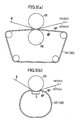
- FIG. 5(a) shows an apparatus in which the pressurizing part is composed of a calender roller CR and a pressing roller PR
- FIG. 5(b) is an apparatus in which the pressurizing part is composed of a calender roller CR and a shoe S.
- an endless calendering belt 100 and the paper W, which is subjected to the calendering process, are sandwiched in the pressurizing part.
- the surface of the calender roller CR which comes into contact with the paper W is smooth and is heated to about 100°C to 200°C by a heating apparatus (not shown).
- these calendering apparatuses can make one surface of the rugged paper W adequately smooth, and the density of the paper W will not exhibit marked local variations.
- the calendering apparatuses of FIGs. 5(a) and 5(b) also have the advantage of excellent durability, because the calendering belt 100 is relatively long, and the heat generated in the pressurizing part is radiated efficiently.
- calendering belts have been designed in which the layer on the web side is made of a comparatively flexible high molecular weight material, and the layer on the pressing side is made of a high molecular weight elastic material which is comparatively hard.
- a belt is disclosed in Unexamined PCT Publication No. 501852/1998.
- the calendering belt 100 which consists chiefly of high-molecular elastic material, lacks adequate heat resistance, and the portion which comes in contact with the calender roller CR readily deteriorates as a result of exposure to heat.
- the heat of the calender roller CR is intercepted by the paper W, and is not transmitted to the calendering belt 100 which is on the back side of the paper W.
- the width of the calendering belt 100 is usually greater than the width of the paper W, both margins of the calendering belt 100 will come into direct contact with the calender roller CR at a high temperature in the pressurizing part of the apparatus. As a result, at both margins of the calendering belt 100, cracks may be generated, and wear becomes more severe due to deterioration and distortion caused by heat.
- fluorocarbon resins such as PTFE (polytetrafluoroethylene) are known as high molecular weight elastic materials having excellent heat resistance and durability, they are expensive, and therefore it is not realistic to manufacture a relatively long calendering belt 100 from such materials.
- PTFE polytetrafluoroethylene
- the improved calendering belt in accordance with the invention is an endless belt comprising a main central portion, and right and left portions located along the right and left sides of the main central portion, said right and left portions comprising high molecular weight elastic material with heat resistance greater than the heat resistance of the main central portion, and said main central portion comprising high molecular weight elastic material having durability higher than the durability of the right and left portions.
- the improved endless calendering belt also preferably has reinforced edge portions located along the outer edges of the right and left portions, the reinforced edge portions comprising high molecular weight elastic material having durability higher than the durability of said right and left portions.
- the right and left portions do not readily deteriorate as a result of heat, even if they come into direct contact with the hot calender roller, because the heat resistance of the right and left portions is higher than that of the main portion.
- the main portion is not worn out easily even if it is repeatedly compressed in the pressing part of the calendering apparatus, because the durability of the main portion is higher than that of the right and left portions.
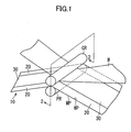
- FIG. 1 is a perspective view of a calendering apparatus in which a calendering belt of the invention is used;
- FIG. 2(a) is a sectional view taken on plane 2-2 of FIG. 1, showing a paper web in place on the main portion of the belt;
- FIG. 2(b) is a sectional view, corresponding to FIG. 2(a), but in which the paper web is laterally displaced;
- FIG. 3 is a sectional view taken on plane 2-2 of FIG. 1, showing the use of a calendering belt in accordance with the invention, provided with reinforced edge portions;
- FIG. 4(a) is a sectional view of the main portion of the calendering belt, formed with layers comprising high-molecular elastic material on the obverse and reverse sides of a base portion;
- FIG. 4(b) is a sectional view of the main portion of a calendering belt in accordance with the invention, in which high-molecular elastic material is provided throughout the entire base portion, on the paper contacting side only;
- FIG. 4(c) is a sectional view of the main portion of a calendering belt in accordance with the invention, in which high-molecular elastic material is provided in a part of the base portion, on the paper contacting side only;
- FIG. 5(a) is a schematic elevational view of a calendering apparatus in which a calendering belt in accordance with the invention is used, and in which the pressurizing part is composed of a calender roller and a pressing roller;
- FIG. 5(b) is a schematic elevational view of a calendering apparatus in which a calendering belt in accordance with the invention is used, and in which the pressurizing part is composed of a calender roller and a shoe;
- FIG. 6 is a perspective view of a tensile test apparatus to test durability of a calendering belt in accordance with the invention.
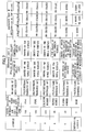
- FIG. 7 is a table showing the results of tests carried out using the test apparatus of FIG. 6.
- FIG. 1 shows the same apparatus in perspective view.
- the calendering belt 10 As in the case of a conventional calendering belt, the calendering belt 10 according to the invention comprises high molecular weight elastic material as a whole, and has a web side WP which comes into contact with the paper W as well as a pressing side MP which comes into contact with the pressing roller PR. In use, the belt 10 passes between the calender roller CR and the pressing roller PR of the calendering apparatus, and the paper W is on the web side WP.
- the calendering belt 10 comprises three sections: a main portion 30 located centrally between the side edges, and right and left marginal portions 20, located on the respective sides of the main portion 30.
- the right and left portions 20 and 20 are composed of a high molecular weight elastic material with high heat resistance, and the main portion 30 is made of high molecular weight elastic material having high durability.
- High molecular weight elastic materials having suitable heat resistance, for composing the right and left marginal portions 20 of the belt include PTFE (polytetrafluoroethylene) which is a fluoro resin, FEP (copolymer of tetrafluoroethylene/hexafluoroethylene), ETFE (copolymer of ethylene/tetrafluoroethylene), AMC (acrylic rubber) which is a heat-resisting rubber materials, EAR (ethylene acrylic rubber), EPDM (ethylene propylenediene rubber), fluoro rubber, silicone rubber, CM (chlorinated polyethylene rubber), CSM (chlorosulfonated polyethylene rubber), IIR (isobutylene-isoprene rubber) and so forth.
- PTFE polytetrafluoroethylene
- FEP copolymer of tetrafluoroethylene/hexafluoroethylene
- ETFE copolymer of ethylene/tetrafluoroethylene
- AMC acrylic rubber which is a
- the paper W which undergoes the calendering process as shown in FIG. 2(a) is usually in register with the main portion 30 of the calendering belt 10 at the location of the pressing part of the calendering apparatus, and the width of the main portion 30 is almost equal to the width of the paper web W.
- heat from the calender roller CR is intercepted by the paper W, and is not transmitted readily to the calendering belt 10 when the paper and calendering belt are compressed between the calender roller CR and the pressing roller PR. Therefore, high temperatures, at which the main portion 30 of the belt 10 deteriorates, are not transmitted to the main portion 30 of the belt.
- Expensive, heat-resistant, high molecular weight elastic material is needed only for the right and left portions 20. Consequently, the manufacturing cost of the belt can be reduced by adoption of the above-described composition and structure. Moreover, the belt does not readily wear out, even though it comes into contact with the pressing roller, because the main portion of the belt comprises a high molecular weight elastic material having high durability.
- the sideward edges of the right and left portions of a calendering belt are places where the pressure applied on the belt is release, and when the belt is installed in a calendering apparatus, these edges are likely to knock against various machine parts. Consequently, it is desirable that those edges be stronger than other sections.
- durability may be improved by providing reinforced edge portions 40, which comprise high molecular weight elastic material with high strength, at the right and left edges of the calendering belt 102.
- compositions and the manufacturing methods of the calendering belt 10 of the invention shown in FIGs. 2(a) and 2(b) will now be explained.
- FIGs. 4(a), 4(b) and 4(c) are sectional views of the main portion 30 of various calendering belts 10 in accordance with the invention.
- the main portion 30 comprises a base portion 32 and a resin part 34.
- the base portion 32 comprises a woven fabric composed of warp and weft yarns, a cloth in which a warp and weft are made to overlap each other, or a cloth in which an elongate cloth element is wound in a spiral.
- the purpose of the base portion is to impart the strength that is needed for a calendering belt.
- two resin parts 34 which comprise a high molecular weight elastic material, lie respectively on the obverse and reverse sides of a base portion 32.
- the high molecular weight elastic material is caused to impregnate the base portion 32.
- high molecular weight elastic material is caused to impregnate the base portion 32 and the high molecular weight elastic material is caused to accumulate, as a resin part 34, on only one side of the belt, which is the side that comes into contact with the paper web.
- FIG. 4(b) two resin parts 34, which comprise a high molecular weight elastic material
- the high molecular weight elastic material is caused to impregnate a part of the base portion 32, and the high molecular weight elastic material is caused to accumulate only on the one side of the belt that comes into contact with the paper.
- the machine-contacting side is composed of the base portion 32 only.
- One method is to impregnate the base portion 32 with the high molecular weight elastic material, and then cause the elastic material to accumulate further on the base portion and cure to form a first layer of high molecular weight elastic material on one side of the base portion, then reversing the assembly, impregnating the base portion 32 with high molecular weight elastic material on its other side, and then accumulating and curing further elastic material to form a second layer of the high molecular weight elastic material on said other side of the base portion.
- the assembly is not reversed. Rather, the high molecular weight elastic material is made to impregnate and pass through the base portion 32 to form one layer on the bottom side, and then further high molecular weight elastic material is accumulated onto the base portion 32 to form the other layer.
- high molecular weight elastic material is caused to impregnate the central part of the base portion 32, which corresponds to the main portion 30, and is then spread and caused to accumulate further on the central part of the base portion.
- a high molecular weight elastic material having a heat resisting property is caused to impregnate the parts of the base portion 32 corresponding to the right and left portions 20 of the belt.
- the heat-resistant, high molecular weight elastic material is spread and accumulated on the right and left portions 20. Afterwards the entire assembly is heated, and the high molecular weight elastic materials are cured, so that the right and left portions 20 are integrated with the main portion 30.
- the high molecular weight elastic materials mix, and an IPN (inter penetration network) is formed, strongly bonding both materials.
- the union at the boundaries where the right and left portions 20 meet the main portion 30 becomes stronger.
- the methods of manufacturing the right and left portions 20 and the main portion 30 are not limited to the above-mentioned examples, and a variety of other manufacturing methods can be adopted.
- Example 1 polyurethane was used in the main portion and PTFE was used for the right and left portions.
- the width of each of the right and left portions was 150 mm, and the width of the main portion was 200 mm, so that the total width of the calendering belt was 500 mm.
- the calendering belt of Example 2 had the same composition as the belt of Example 1, but the width of each of the right and left portions was 100 mm, and the width of the main portion was 300 mm.
- Example 3 polyurethane was used in the main portion and silicone rubber was used for the right and left portions.
- the width of each of the right and left portions was 100 mm and the width of the main portion was 300 mm. so that the calendering belt had a total width of 500 mm.
- the belt of Example 4 had the same composition as that of Example 3, but the width of each of the right and left portions was 80 mm and the width of the main portion was 340 mm.
- polyurethane was used in the main portion and fluoro rubber was used for the right and left portions.
- the width of each of the right and left portions was 50mm, and the width of the main portion was 400 mm, for a total belt width of 500 mm.
- the tensile testing apparatus shown in FIG. 6 was used to test the durability of each calendering belt made according to the above-described examples, and endurance testing was conducted.
- the tensile test apparatus consisted of a feeding roller DR, a heating roller HR, and a support roller SR.
- the endless calendering belt 10 was installed on the feeding roller DR support roller SR and the heating roller HR was arranged above the feeding roller DR, to provide a compressing part.
- a tensile force was applied to the calendering belt 10 by the feeding roller DR and the support roller SR, and the belt was compressed by the heating roller HR and the feeding roller DR.
- the width of each roller DR, HR, and SR was 500mm.
- a heat insulator HR1 covered the central portion of the heating roller HR, the distances from the ends of the insulator HR1 to the ends of the heating roller HR being 100 mm.
- the heat insulator HR1 performed a heat intercepting function equivalent to that of the paper web W in an actual calendering apparatus.
- endurance test I the state of the belt was examined after a run for 100 hours under a tensile force of 1000kgf/500mm, a pressure 1kgf/cm 2 , and at heating roller temperatures of 150°C and 300°C.
- endurance test II the testing apparatus was run until cracks were generated in the calendering belt or separation occurred. Endurance test II was carried out at a tensile force 1000kgf/500mm and a heating roller temperature of 200°C, at three different pressures: 10kgf/cm 2 50kgf/cm 2 , and 100kgf/cm 2 .
- the calendering belt 10 of the invention exhibited overall excellent durability compared with the conventional calendering belt.
- the test results show that a crack is not likely to be caused at the boundaries where the right and left potions 20 meet the main portion 30, and durability is improved, provided that the right and left portions 20 are 80cm or more in width.
- the calendering belt in accordance with the invention has the advantages of excellent durability and heat resistance property at a relatively low cost.
Landscapes
- Paper (AREA)
- Casting Or Compression Moulding Of Plastics Or The Like (AREA)
Abstract
Description
10kgf/cm2 50kgf/cm2, and 100kgf/cm2.
Claims (2)
- An endless calendering belt for use in a calendering apparatus for paper manufacture in which a pressurizing part is composed of a pressing means and a heated calender roller, the belt comprising a main central portion, and right and left portions located along the right and left sides of the main central portion, said right and left portions comprising high molecular weight elastic material with heat resistance greater than the heat resistance of the main central portion, and said main central portion comprising high molecular weight elastic material having durability higher than the durability of the right and left portions.
- An endless calendering belt according to claim 1, having reinforced edge portions located along the outer edges of the right and left portions, the reinforced edge portions comprising high molecular weight elastic material having durability higher than the durability of said right and left portions.
Applications Claiming Priority (2)
| Application Number | Priority Date | Filing Date | Title |
|---|---|---|---|
| JP2001195847 | 2001-06-28 | ||
| JP2001195847A JP4524055B2 (en) | 2001-06-28 | 2001-06-28 | Calendar belt |
Publications (3)
| Publication Number | Publication Date |
|---|---|
| EP1270808A2 true EP1270808A2 (en) | 2003-01-02 |
| EP1270808A3 EP1270808A3 (en) | 2003-02-12 |
| EP1270808B1 EP1270808B1 (en) | 2006-05-24 |
Family
ID=32866142
Family Applications (1)
| Application Number | Title | Priority Date | Filing Date |
|---|---|---|---|
| EP02009612A Expired - Lifetime EP1270808B1 (en) | 2001-06-28 | 2002-04-26 | Belt for calendering |
Country Status (7)
| Country | Link |
|---|---|
| US (1) | US6780287B2 (en) |
| EP (1) | EP1270808B1 (en) |
| CN (1) | CN1182295C (en) |
| AU (1) | AU783423B2 (en) |
| CA (1) | CA2383771C (en) |
| DE (1) | DE60211598T2 (en) |
| TW (1) | TWI223681B (en) |
Cited By (3)
| Publication number | Priority date | Publication date | Assignee | Title |
|---|---|---|---|---|
| WO2005111303A1 (en) * | 2004-05-13 | 2005-11-24 | Voith Patent Gmbh | Press roller |
| EP2392729A1 (en) * | 2010-06-01 | 2011-12-07 | Voith Patent GmbH | Belt assembly and method for treating a sheet of paper in a calendar assembly |
| EP2028317A4 (en) * | 2006-06-05 | 2012-04-25 | Ichikawa Co Ltd | BELT FOR SHOT PRESS |
Families Citing this family (3)
| Publication number | Priority date | Publication date | Assignee | Title |
|---|---|---|---|---|
| EP1653001B1 (en) * | 2003-08-07 | 2012-12-05 | Yamauchi Corporation | Press with press belt and method for producing a press belt |
| DE102005046812A1 (en) * | 2005-09-30 | 2007-04-05 | Voith Patent Gmbh | Band for transferring a fibrous web to be produced |
| DE102021117647A1 (en) * | 2021-07-08 | 2023-01-12 | Voith Patent Gmbh | Process and machine for producing a fibrous web |
Family Cites Families (14)
| Publication number | Priority date | Publication date | Assignee | Title |
|---|---|---|---|---|
| US290147A (en) * | 1883-12-11 | John keil tullis | ||
| US4238287A (en) * | 1979-04-26 | 1980-12-09 | Beliot Corporation | Extended nip press with transverse stiffening means in the belt |
| US4552620A (en) | 1983-09-19 | 1985-11-12 | Beloit Corporation | Paper machine belt |
| US4877472A (en) * | 1988-10-31 | 1989-10-31 | Beloit Corporation | Method of making a bearing blanket |
| US5422165A (en) * | 1993-06-10 | 1995-06-06 | Morrison Company, Inc. | Edge-protected belting |
| DE4322322A1 (en) * | 1993-07-05 | 1993-11-11 | Voith Gmbh J M | Paper-making press mantle - has a smaller roughness depth on outer side against the paper than on the inner side |
| DE4401580A1 (en) * | 1994-01-20 | 1994-06-01 | Voith Gmbh J M | Paper making press section - has reduced stiffness at edges of units forming press gap to reduce wear at edges |
| SE502960C2 (en) | 1994-06-15 | 1996-02-26 | Nordiskafilt Ab Albany | Arrangement for calendaring |
| DE4443598C2 (en) * | 1994-12-07 | 2000-05-25 | Voith Sulzer Papiermasch Gmbh | Process for producing a press jacket |
| DE19652545B4 (en) * | 1996-12-17 | 2006-03-23 | Voith Sulzer Papiermaschinen Gmbh | Press roll for treating web-shaped goods |
| DE19702138A1 (en) * | 1997-01-22 | 1998-07-23 | Voith Sulzer Papiermasch Gmbh | Press mantle for wet paper web(s) |
| JP3045975B2 (en) * | 1997-04-24 | 2000-05-29 | 市川毛織株式会社 | Shoe press belt |
| DE19728399A1 (en) * | 1997-07-03 | 1999-01-07 | Voith Sulzer Papiermasch Gmbh | Machine for the production of a continuous material web |
| DE19860099A1 (en) * | 1998-12-23 | 2000-07-06 | Voith Sulzer Papiertech Patent | Press jacket and manufacturing method |
-
2002
- 2002-04-24 US US10/131,319 patent/US6780287B2/en not_active Expired - Fee Related
- 2002-04-24 AU AU35635/02A patent/AU783423B2/en not_active Ceased
- 2002-04-24 CN CNB021183317A patent/CN1182295C/en not_active Expired - Fee Related
- 2002-04-26 EP EP02009612A patent/EP1270808B1/en not_active Expired - Lifetime
- 2002-04-26 DE DE60211598T patent/DE60211598T2/en not_active Expired - Lifetime
- 2002-04-29 CA CA002383771A patent/CA2383771C/en not_active Expired - Fee Related
- 2002-04-29 TW TW091108797A patent/TWI223681B/en not_active IP Right Cessation
Cited By (4)
| Publication number | Priority date | Publication date | Assignee | Title |
|---|---|---|---|---|
| WO2005111303A1 (en) * | 2004-05-13 | 2005-11-24 | Voith Patent Gmbh | Press roller |
| US8100817B2 (en) | 2004-05-13 | 2012-01-24 | Voith Patent Gmbh | Press roller |
| EP2028317A4 (en) * | 2006-06-05 | 2012-04-25 | Ichikawa Co Ltd | BELT FOR SHOT PRESS |
| EP2392729A1 (en) * | 2010-06-01 | 2011-12-07 | Voith Patent GmbH | Belt assembly and method for treating a sheet of paper in a calendar assembly |
Also Published As
| Publication number | Publication date |
|---|---|
| CA2383771A1 (en) | 2002-12-28 |
| EP1270808A3 (en) | 2003-02-12 |
| US6780287B2 (en) | 2004-08-24 |
| CN1393598A (en) | 2003-01-29 |
| AU783423B2 (en) | 2005-10-27 |
| DE60211598D1 (en) | 2006-06-29 |
| AU3563502A (en) | 2003-01-02 |
| CN1182295C (en) | 2004-12-29 |
| TWI223681B (en) | 2004-11-11 |
| EP1270808B1 (en) | 2006-05-24 |
| US20030201086A1 (en) | 2003-10-30 |
| CA2383771C (en) | 2008-07-29 |
| DE60211598T2 (en) | 2006-10-26 |
Similar Documents
| Publication | Publication Date | Title |
|---|---|---|
| AU658808B2 (en) | Endless belt for dewatering press | |
| CA2230565C (en) | Shoe press belt | |
| US6921461B2 (en) | Elastic belt for papermaking | |
| EP2367980B1 (en) | Shoe press belt | |
| EP1270808B1 (en) | Belt for calendering | |
| EP0886004A1 (en) | Belt for shoe press | |
| CA2557618C (en) | Heat resistant laminated conveyor belt and manufacturing method thereof | |
| EP2319983B1 (en) | Papermaking press felt | |
| CA1260749A (en) | Endless belt | |
| EP2028317B1 (en) | Belt for shoe press | |
| JPH11301824A (en) | Pressure belt for paper bonding | |
| CA2697840C (en) | Shoe press belt | |
| TW200401066A (en) | Shoe press belt | |
| JP4712504B2 (en) | Method of manufacturing cushion material for heat resistant press | |
| JP4524055B2 (en) | Calendar belt | |
| JP5112640B2 (en) | Cushion material for heat-resistant press | |
| JP2904464B2 (en) | Elastic belt for paper calendar | |
| JPH1053992A (en) | Felt for papermaking | |
| JPH11301825A (en) | Pressurized belt for bonding paper |
Legal Events
| Date | Code | Title | Description |
|---|---|---|---|
| PUAI | Public reference made under article 153(3) epc to a published international application that has entered the european phase |
Free format text: ORIGINAL CODE: 0009012 |
|
| PUAL | Search report despatched |
Free format text: ORIGINAL CODE: 0009013 |
|
| AK | Designated contracting states |
Kind code of ref document: A2 Designated state(s): AT BE CH CY DE DK ES FI FR GB GR IE IT LI LU MC NL PT SE TR |
|
| AX | Request for extension of the european patent |
Free format text: AL;LT;LV;MK;RO;SI |
|
| AK | Designated contracting states |
Designated state(s): AT BE CH CY DE DK ES FI FR GB GR IE IT LI LU MC NL PT SE TR |
|
| AX | Request for extension of the european patent |
Extension state: AL LT LV MK RO SI |
|
| 17P | Request for examination filed |
Effective date: 20030416 |
|
| AKX | Designation fees paid |
Designated state(s): DE FI FR GB IT SE |
|
| GRAP | Despatch of communication of intention to grant a patent |
Free format text: ORIGINAL CODE: EPIDOSNIGR1 |
|
| GRAS | Grant fee paid |
Free format text: ORIGINAL CODE: EPIDOSNIGR3 |
|
| GRAA | (expected) grant |
Free format text: ORIGINAL CODE: 0009210 |
|
| AK | Designated contracting states |
Kind code of ref document: B1 Designated state(s): DE FI FR GB IT SE |
|
| PG25 | Lapsed in a contracting state [announced via postgrant information from national office to epo] |
Ref country code: IT Free format text: LAPSE BECAUSE OF FAILURE TO SUBMIT A TRANSLATION OF THE DESCRIPTION OR TO PAY THE FEE WITHIN THE PRESCRIBED TIME-LIMIT;WARNING: LAPSES OF ITALIAN PATENTS WITH EFFECTIVE DATE BEFORE 2007 MAY HAVE OCCURRED AT ANY TIME BEFORE 2007. THE CORRECT EFFECTIVE DATE MAY BE DIFFERENT FROM THE ONE RECORDED. Effective date: 20060524 |
|
| REG | Reference to a national code |
Ref country code: GB Ref legal event code: FG4D |
|
| REF | Corresponds to: |
Ref document number: 60211598 Country of ref document: DE Date of ref document: 20060629 Kind code of ref document: P |
|
| REG | Reference to a national code |
Ref country code: SE Ref legal event code: TRGR |
|
| ET | Fr: translation filed | ||
| PLBE | No opposition filed within time limit |
Free format text: ORIGINAL CODE: 0009261 |
|
| STAA | Information on the status of an ep patent application or granted ep patent |
Free format text: STATUS: NO OPPOSITION FILED WITHIN TIME LIMIT |
|
| 26N | No opposition filed |
Effective date: 20070227 |
|
| REG | Reference to a national code |
Ref country code: FR Ref legal event code: PLFP Year of fee payment: 14 |
|
| PGFP | Annual fee paid to national office [announced via postgrant information from national office to epo] |
Ref country code: GB Payment date: 20150422 Year of fee payment: 14 Ref country code: DE Payment date: 20150422 Year of fee payment: 14 Ref country code: FI Payment date: 20150409 Year of fee payment: 14 Ref country code: SE Payment date: 20150413 Year of fee payment: 14 |
|
| PGFP | Annual fee paid to national office [announced via postgrant information from national office to epo] |
Ref country code: IT Payment date: 20150410 Year of fee payment: 14 Ref country code: FR Payment date: 20150408 Year of fee payment: 14 |
|
| REG | Reference to a national code |
Ref country code: DE Ref legal event code: R119 Ref document number: 60211598 Country of ref document: DE |
|
| REG | Reference to a national code |
Ref country code: SE Ref legal event code: EUG |
|
| GBPC | Gb: european patent ceased through non-payment of renewal fee |
Effective date: 20160426 |
|
| REG | Reference to a national code |
Ref country code: FR Ref legal event code: ST Effective date: 20161230 |
|
| PG25 | Lapsed in a contracting state [announced via postgrant information from national office to epo] |
Ref country code: DE Free format text: LAPSE BECAUSE OF NON-PAYMENT OF DUE FEES Effective date: 20161101 Ref country code: GB Free format text: LAPSE BECAUSE OF NON-PAYMENT OF DUE FEES Effective date: 20160426 Ref country code: FI Free format text: LAPSE BECAUSE OF NON-PAYMENT OF DUE FEES Effective date: 20160426 Ref country code: FR Free format text: LAPSE BECAUSE OF NON-PAYMENT OF DUE FEES Effective date: 20160502 |
|
| PG25 | Lapsed in a contracting state [announced via postgrant information from national office to epo] |
Ref country code: SE Free format text: LAPSE BECAUSE OF NON-PAYMENT OF DUE FEES Effective date: 20160427 Ref country code: IT Free format text: LAPSE BECAUSE OF NON-PAYMENT OF DUE FEES Effective date: 20160426 |