EP1270506A1 - Micro-actuator and method of manufacturing the actuator - Google Patents
Micro-actuator and method of manufacturing the actuator Download PDFInfo
- Publication number
- EP1270506A1 EP1270506A1 EP01912448A EP01912448A EP1270506A1 EP 1270506 A1 EP1270506 A1 EP 1270506A1 EP 01912448 A EP01912448 A EP 01912448A EP 01912448 A EP01912448 A EP 01912448A EP 1270506 A1 EP1270506 A1 EP 1270506A1
- Authority
- EP
- European Patent Office
- Prior art keywords
- microactuator
- movable mass
- driving electrode
- elastic support
- support beam
- Prior art date
- Legal status (The legal status is an assumption and is not a legal conclusion. Google has not performed a legal analysis and makes no representation as to the accuracy of the status listed.)
- Withdrawn
Links
Images









Classifications
-
- H—ELECTRICITY
- H02—GENERATION; CONVERSION OR DISTRIBUTION OF ELECTRIC POWER
- H02N—ELECTRIC MACHINES NOT OTHERWISE PROVIDED FOR
- H02N1/00—Electrostatic generators or motors using a solid moving electrostatic charge carrier
- H02N1/002—Electrostatic motors
- H02N1/006—Electrostatic motors of the gap-closing type
- H02N1/008—Laterally driven motors, e.g. of the comb-drive type
Definitions
- the present invention relates to a micro-actuator and in particular to a microactuator using an electrostatic impact driving mechanism, and to a method of making such a microactuator.
- micro-actuators so far proposed have had a limited extent of their applicability.
- an impact driving mechanism using a piezoelectric element has been proposed (see Toshiro Higuchi, Masahiro Watanabe, Ken-ichi Watanabe, "Ultra-precision Positioning Mechanism utilizing Rapid Deformation of a Piezoelectric Element", Journal of the Society of Precision Engineering, 54-11, 2107 (1998), which using a frictional force and an piezoelectric element, has both a very small displacement in a nanometer range and a movable distance utmost minimum in principle, but needs to be built up individually and has a limitation in miniaturization.
- microactuators so far proposed are poor in reliability measure such as to prevent entry of dust and moisture in air and are thus inferior in environmental reliability.
- a microactuator with an electrostatic impact driving mechanism which as set forth in claim 1 in the appended claims comprises: a closed receptacle formed of an outer frame part, a pedestal part and a lid part; an elastic support beam member disposed in the said closed receptacle; a fixing member disposed in the said closed receptacle and securely connecting a first end of the said elastic support beam member to the said pedestal part; a movable mass member disposed in the said closed receptacle and securely connected to a second end of the said elastic support beam member; a driving electrode and a stopper member disposed in the said closed receptacle, each of which is securely connected to the said pedestal part and spacedly juxtaposed with the said movable mass member; and a power supply circuit disposed in the inside or the outside of the said closed receptacle for applying a voltage between the said movable mass and driving electrode members, wherein the microactuator is so
- the microactuator so constructed with the electrostatic driving mechanism is of a structure that can be built up by an integrated circuit process technology, and which permits the components to be integrated into an identical device, which eliminates the need to fabricate individual components, and which allows the product to be made that is extremely small in size
- the microactuator with the electrostatic impact driving mechanism may as set forth in claim 2 in the appended claims be characterized in that the said first end of the said elastic support beam member is securely connected to a single fixing element constituting the said fixing member, the said movable mass member is securely connected to the said second end of the said elastic support beam member at two places thereon, the said single fixing element is disposed so as to make the said movable mass member capable of rocking over a surface of the said pedestal part, the said driving electrode and stopper members comprise a first and a second driving electrode and a first and a second stopper member, wherein the said first driving electrode and stopper element are each disposed in front of the said movable mass member while the said second driving electrode and stopper elements are each disposed in rear of the said movable mass member, and the said voltage is applied between a said driving electrode and the said movable mass member via the said outer frame part.
- selecting the first or second drive electrode with which the voltage is applied allows the microactuator to be bodily moved forth or back.
- the microactuator with the electrostatic impact driving mechanism may as set forth in claim 3 in the appended claims be characterized in that the said elastic support beam member is capable of elastically supporting the said movable mass member in two axial directions perpendicular to each other, the said elastic support beam member has a pair of first ends securely connected, respectively, to two fixing elements constituting the said fixing member, the said second end of the said elastic support beam member is securely connected at one place to the said movable mass member, the said two fixing elements are arranged so as to make the said movable mass member capable of rocking forth and back and right and left over a surface of the said pedestal part, the said driving electrode and said stopper members comprise a first, a second, a third and a fourth driving electrode and a first, a second, a third and a fourth stopper element, wherein the said first driving electrode and stopper member, the said second driving electrode and stopper member, the said third driving electrode and stopper element and the said fourth driving electrode and stopper element are disposed in front of, in rear
- This construction permits the microactuator to be bodily moved two dimensionally in a given plane and to be so moved in any direction as desired.
- the microactuator with the electrostatic impact driving mechanism may as set forth in claim 4 in the appended claims be characterized in that the said movable mass member is fan-shaped and securely connected to the said second end of the said elastic support beam member, the said first end of said elastic support beam member is securely connected to the said fixing member, the said fixing member is arranged so as to make the said movable mass member capable of rocking about the said fixing member over a surface of the said pedestal part, the said driving electrode member and the said stopper member are each fan-shaped, and the said voltage is applied between the said driving electrode member and the said movable mass member via the said outer frame part.
- the microactuator is rotationally driven and may be applied to form a motor or the like.
- the microactuator with the electrostatic impact driving mechanism may as set forth in claim 5 in the appended claims be characterized in that the said movable mass member is supported in suspension by the said elastic support beam member which obliquely support it, the said driving electrode member is disposed below the said movable mass member, the said stopper member is disposed in front or in rear of the said movable mass member, and the said voltage is applied between the said driving electrode member and the said movable mass member via the said outer frame part.
- the microactuator with the electrostatic impact driving mechanism may as set forth in claim 6 in the appended claims be characterized in that the elastic support beam member has a pair of first ends securely connected, respectively, to two fixing elements constituting the said fixing member, the said second end of the said elastic support member is securely connected at one place thereon to the said movable mass member, the said two fixing elements are arranged so as to make the said movable mass member capable of rocking over a surface of the said pedestal part and are disposed in front and in rear of the said driving electrode and movable mass members, and the said voltage is applied between the said driving electrode member and the said movable mass member via the said outer frame part.
- the said two fixing elements may be monolithic with the said outer frame part as set forth in claim 7 in the appended claims
- the fixing elements serve as stopper members and are monolithic with the outer frame part.
- the microactuator with the electrostatic impact driving mechanism as set forth in claim 8 in the appended claims is characterized in that the said movable mass member is securely connected to a pair of such elastic support beam members as aforesaid, which are in turn securely connected to a pair of such fixing members as aforesaid, respectively.
- microactuator permits the movable mass member to be supported as well-balanced in a horizontal plane and hence to be rocked stably and smoothly there.
- the microactuator with the electrostatic impact driving mechanism as set forth in claim 9 in the appended claims is characterized in that the said driving electrode member is split into two driving electrode elements, which are energizable independently of each other.
- This construction of the microactuator utilizes a torsion effect of the elastic support beam members and thereby allows the microactuator to be advanced in a selected direction alterable, by applying a voltage only to one of the electrodes selected.
- microactuator with the electrostatic impact driving mechanism may as set forth in claim 10 in the appended claims be characterized in that the said outer frame part is composed of Si single crystal, and the said pedestal and lid parts are composed of a material having a preselected friction coefficient.
- microactuator with the electrostatic impact driving mechanism may as set forth in claim 11 in the appended claims be characterized in that the said material having a preselected friction coefficient is pyrex glass.
- microactuator with the electrostatic impact driving mechanism may as set forth in claim 12 in the appended claims be characterized in that the said outer frame part, the said elastic support beam member, the said movable mass member, the said driving electrode member and the said stopper member are composed of a Si single crystal, and the said pedestal and lid parts are composed of a material having a preselected friction coefficient.
- microactuator with the electrostatic impact driving mechanism may as set forth in claim 13 in the appended claims be characterized in that the said outer frame part is composed of Si single crystal, and the said pedestal and lid parts are composed of a material having a preselected friction coefficient.
- microactuator with the electrostatic impact driving mechanism may as set forth in claim 14 in the appended claims be characterized in that the said material having a preselected friction coefficient is pyrex glass.
- the present invention also provides a linear driving stage, which may as set forth in claim 15 in the appended claims comprise: a fixed platform; a movable platform slidably mounted on the said fixed platform; and a microactuator with an electrostatic impact driving mechanism as set forth in any one of claims 1 to 12, or a microactuator as set forth in claim 13, the said microactuator being fastened to the said movable platform.
- a linear driving stage which may as set forth in claim 15 in the appended claims comprise: a fixed platform; a movable platform slidably mounted on the said fixed platform; and a microactuator with an electrostatic impact driving mechanism as set forth in any one of claims 1 to 12, or a microactuator as set forth in claim 13, the said microactuator being fastened to the said movable platform.
- the present invention also provides a linear X-Y driving stage, which may as set forth in claim 16 in the appended claims comprise: a fixed platform; a first movable platform slidably mounted on the said fixed platform for movement in a first direction; a second movable platform slidably mounted on the said first movable platform for movement in a second direction orthogonal to the said first direction; and a microactuator with an electrostatic impact driving mechanism as set forth in any one of claims 1 to 12, or a microactuator as set forth in claim 13, the said microactuator being fastened to the said second movable platform.
- the invention also provides a drive unit which as set forth in claim 17 in the appended claims comprises a movable body and a plurality of microactuators using electrostatic impact driving mechanism incorporated therein, each of which is a microactuator as set forth in any one of claims 1 to 12 or a microactuator as set forth in claim 13.
- a method of making a microactuator with an electrostatic impact driving mechanism by monolithically forming from a Si single crystal substrate, an outer frame part, and an elastic support beam, a movable mass, a driving electrode and a stopper member, and forming a pedestal part and a lid part from a material having a preselected friction coefficient
- which method as set forth in claim 18 in the appended claims is characterized by comprising the steps of: a) forming the said driving electrode member on a front surface of the said Si single crystal substrate; b) etching the said Si substrate from its back side in order to make the said elastic support beam and movable mass members floating in the air; c) attaching a first member having a preselected friction coefficient to rear surfaces of the said Si substrate; d) etching the said Si substrate from its front side in order to form the said outer frame part, the said elastic support beam, movable mass members, the said driving electrode member and
- the method of making a microactuator with an electrostatic impact driving mechanism may as set forth in claim 19 in the appended claims be specifically characterized in that etching steps b), d) and e) are carried out each by inductively coupled plasma - reactive etching.
- the method of making a microactuator with an electrostatic impact driving mechanism may as set forth in claim 20 in the appended claims be specifically characterized in that steps c) and f) in which a first or second member having the preselected friction coefficient is attached to rear or front surfaces of the Si substrate are carried out each by anodic joining of pyrex glass as the first or second member to said Si substrate.
- Fig. 1 is a plan view illustrating the makeup of a microactuator using an electrostatic impact driving mechanism in the first embodiment of the present invention
- Fig. 2 is a cross sectional view of the microactuator taken along the line A-A in Fig. 1
- Fig. 1 shows the inside makeup of the microactuator and its lid part is omitted from illustration.
- This microactuator M using an electrostatic impact driving mechanism is made up of a movable mass member 3 supported by a pair of elastic support beams 2 and a pair of fixing members 1, a pair of (first and a second) driving electrodes 4 disposed in front and in rear of the movable mass member 3, respectively, a pair of (first and second) stopper members 5 disposed at two opposite sides of each electrode 4, and a closed receptacle for hermetically sealing the fixing members 1, the driving electrodes 4, the stopper members 5 and the members mentioned above.
- the closed sealing receptacle is made up of an outer frame part 6 formed of a Si single crystal substrate, a pedestal part 14, and a lid part 16.
- each of the elastic support beams 2 comprises four thin elastic plates 2a, 2b, 2c and 2d, and a thin elastic plate 2e having one end of each of these thin elastic plates securely connected thereto for supporting these thin elastic plates parallel to one another.
- the outer thin elastic plates 2a and 2d have their other ends securely connected to the movable mass member 3 while the inner thin elastic plates 2b and 2c have their other ends securely connected to the opposite ends 1a and 1'a of the fixing member 1, respectively.
- a power supply circuit 9 comprising a power supply 7 and a switch 8 is connected between the movable mass member 3 and one of the (first) driving electrodes 4.
- This power supply circuit 9 may be disposed either outside or inside of the receptacle.
- another (second) power supply circuit 9' comprising a power supply 7' and a switch 8' is connected between the. movable mass member 3 and the other (second) driving electrode 4.
- the entire actuator M is mounted on a platform 10 for self-driving thereon.
- the pedestal part 14 and the lid part 16 can be formed, preferably, of pyrex glass.
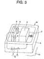
- Figs. 3 to 6 are conceptual views used to illustrate the principles of operation of the microactuator of the present invention. It should be noted here that for the sake of facilitating the illustration, the second electrode 4, the second stopper member 5 and the second power supply 9' are not shown. One end of the power supply circuit 9 is shown connected to the movable mass member 3 via the outer frame 6 and the elastic support beam (spring) 2.
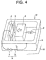
- the switch 8 of the power supply circuit 9 disposed outside of the outer frame 6 is turned ON, as shown in Fig. 4, to apply a voltage across a spacing between the driving electrode 4 and the movable mass member 3 from the power supply 8. Then, an electrostatic force is generated across the spacing between the movable mass member 3 and the driving electrode 4, thereby causing the movable mass member 3 to begin moving towards the driving electrode 4 and then to be slowly accelerated.
- the reaction force generated in the direction opposite to the direction of acceleration namely the force which the actuator M receives from the platform 10 is set not to exceed the static frictional force between the actuator M and the platform 10.
- the movable mass member 3 will continue to be accelerated until it comes into collision with the stopper members 5. Concurrently with the collision, the kinetic energy of the movable mass member 3 is transmitted to the entire body of the actuator M, and the actuator M is bodily moved upon the transmitted energy or force exceeding the static frictional force with the platform 10. And, the actuator M continues to move until the kinetic energy it acquired from the movable mass member 3 is lost by the dynamic frictional force between the actuator M and the platform 10 and then comes to a halt.
- adding a mechanism adapted to effect electrostatic or magnetic attraction to the pedestal part 14 or the lid part 16 allows movement on a vertical wall or a ceiling. Further, the friction may be caused to occur between the actuator M and the platform 10 not by the actuator's own weight but by a weight of a bias spring.
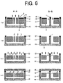
- Fig. 7 illustrates the process of manufacturing the first embodiment of the present invention. It should be noted here that in Fig. 7, each of the views shown at the left hand side corresponds to the cross section taken along the line A-A in Fig. 1 and each of the views shown at the right hand side corresponds to the cross section taken along the line B-B in Fig. 1.
- An actuator being made here has a structure obtained in the manner that in the interest of making the mass of the movable mass member 3 greater, the movable mass member 3 and the fixing member 1 are first micromachined from a Si (silicon) substrate by etching the substrate from the front side surface to the back side surface, and then the fixing member 1 and the driving electrodes 4 are joined to a pyrex glass plate becoming the pedestal part 14.
- the Si substrate 11 which is high in conductivity and of a thickness of 225 micrometers, has an Al (aluminum) layer 12 built up thereon. Then, by using a first photomask (not shown), patterning is effected of the Al layer 12 for forming an electrode.
- a resist layer 13 is applied to the back of the substrate, and patterning is effected of the resist layer by using a second photomask (not shown) to bring the movable mass member into the state that it floats in the air. And, in order to bring the movable mass member into the state that it floats in the air, as shown in Fig.
- the substrate is subjected from its back to a first ICP-RIE (inductively coupled plasma - reactive ion etching step). Those portions of the Si substrate 11 which are becoming the outer frame 6 are then left with the resist thereon and therefore not etched.
- ICP-RIE inductively coupled plasma - reactive ion etching step
- the resist layer 13 is removed, and as shown in Fig. 7 at (e) the pyrex glass plate becoming the pedestal part 14 is joined by anodic joining to the Si substrate 11 and resist layers 15 are applied to the surface of the substrate 11 and the Al layer 12, followed by patterning thereof such as to monolithically form the Si substrate 11 portions becoming the outer frame part, the elastic support beams 2 and the movable mass member 3.
- a second ICP-RIE process step is carried out from the front side.
- the patterned resists are removed, and as shown in Fig. 8 at (c) a third ICP-RIE process step is performed from the front side to dig the substrate down, thereby forming the elastic support beams 2 and the movable mass member 3 so that they lie out of contact with the lid part 16, namely they lie floating in the air. Those portions of the Si substrate 11 and the fixing member 1 on which Al remain to lie are not etched.
- a pyrex glass plate becoming the lid part 16 is joined to the Al layers 12 by anodic joining (a method of joining in which pyrex glass is brought into contact with Si and an elevated electric field is applied between the pyrex glass plate and the Si substrate), or otherwise with an adhesive agent. In this manner, the microactuator using the electrostatic impact driving mechanism is finished up.
- microactuator units are concurrently fabricated and cut by a dicing saw into chips as individual microactuator products.
- the method of manufacture described above uses a highly advanced Si integrated circuit process technology and hence allows mass production of microactuators of a given design and size in a lump with their constituent elements such as the movable mass member, elastic support beams and driving electrodes integrated with precision. Thus, it permits such microactuators to be produced at a reduced cost and with a minimum individual difference.
- This method of manufacture also eliminates the need to fabricate and adjust the individual components and permits making them extremely small in size.
- this method of manufacture permits a microactuator to be formed in an enclosed structure having its top and bottom formed of pyrex glass and its sides formed of silicon crystal, and hence free from entry of dust and moisture, high in environmental reliability and with an extended service life.
- microactuators are made by the method of manufacture, one having the elastic support beams of 500 micrometers long and the other having those of 600 micrometers long. These microactuators are shown to have their driving voltages of 70 and 20 volts required to bring the mass member 3 into collision with the stopper members and their resonant frequencies of 368 Hz and 100 Hz, respectively.
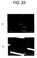
- Figs. 22A and 22B are the electron microscope photographs of such microactuators used in such measurements.
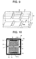
- Fig. 9 is a decomposed perspective view of the second embodiment of the present invention.
- a movable platform 17 formed in its lower surface with V-shaped recesses 17a by anisotropic etching is placed on a fixed platform 18 formed in its upper surface with a V-shaped projections 18a by anisotropic etching so that with the V-shaped recesses 17a fitted on the V-shaped projections 18a the upper platform 17 may be slidably moved over the fixed platform, thereby to making up a linear driving stage 19.
- the movable platform 17 has a one-dimensionally driven impact microactuator M fastened to its upper surface, which enables the movable platform 17 to be moved on the fixed platform 18 in the directions indicated by the arrows.
- the actuator M is basically of the structure which as shown in Fig. 10 and in Fig. 11 that is a cross sectional view thereof taken along the line A-A, is the same as in the first embodiment described above; hence its repeated description in detail is omitted. It is shown, however, that the lid part 16 is formed with a through-hole 20 for wiring such that the driving electrodes 4, the fixing member 1 of the movable mass member 3 and the outer frame part 6 may have an voltage applied thereto or may otherwise be grounded.
- Fig. 12 is a decomposed perspective view showing the third embodiment of the present invention.
- an X-direction movable platform 21 formed in its lower surface with V-shaped recesses 21a by anisotropic etching a Y-direction movable platform 22 formed in its upper surface with V-shaped projections 22a and in its lower surface with V-shaped recesses 22b perpendicular thereto by anisotropic etching, and a fixed platform 23 formed in its upper surface with V-shaped projections 23a by anisotropic etching are assembled together so that with the V-shaped recesses 21a fitted with the V-shaped projections 22a and the V-shaped recesses 22b fitted with the V-shaped projections 23a the platform 21 may be slidably moved on the platform 22 and the latter may be slidably moved on the platform 23, thereby making up an XY driving stage 24.
- the X-direction movable platform 21 has a two-dimensionally driven impact microactuator M1 fastened to its upper surface, which enables the X-direction movable platform 21 to be moved on the Y-direction movable platform 22 in a X-direction indicated by the arrow and the Y-direction movable platform 22 to be moved on the fixed platform 23 in a Y-directions indicated by the arrow.
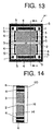
- the basic makeup of this actuator M1 is shown in Fig. 13 and in Fig. 14 that is a cross sectional view thereof taken along the line A-A.
- the microactuator M1 comprises a movable mass member 3 supported by a pair of T-shaped elastic support beams 2 fixed to fixing elements 1 disposed at four corners in the closed receptacle, two pairs of driving electrodes 4 spacedly juxtaposed with the movable mass member 3 at its front and back sides and at its right and left hand sides, respectively, each pair of stopper members 5 disposed at opposite sides of each driving electrode 4, respectively, and an outer frame part 6 made from a Si substrate and having side walls which support and surround therewith the fixing elements 1, the driving electrodes 4 and the stopper members 5.
- each driving electrode 4 and the movable mass member 3 there is connected to each driving electrode 4 and the movable mass member 3, respectively, a power supply circuit such that turning its switch ON and OFF generates a kinetic energy sufficient to move the actuator M1 in the X- , Y-direction.
- a power supply circuit such that turning its switch ON and OFF generates a kinetic energy sufficient to move the actuator M1 in the X- , Y-direction.
- applying a voltage between one of the front and back side driving electrodes 4 and the movable mass member 3 while concurrently removing a voltage between one of the right and left hand side driving electrodes 4 and the movable mass member 3 generates a kinetic energy that moves the actuator M1 diagonally or at an angle.
- the actuator M1 is movable by the single device in any direction as desired in a two-dimensional plane.
- the lid part 16 (as shown) or the pedestal part 14 is formed with a wiring through-hole 20 such that the driving electrodes 4, fixing members 1 of the movable mass member 3 and side walls of the outer frame part 6 may have an voltage applied thereto or may otherwise be grounded.
- the recesses formed in the movable platforms 17, 21 and the projections formed on the fixed platforms 18 (22) may be dovetail grooves 17c (21c) and dovetails 18c (22c), respectively, as shown in Fig. 15.
- a plurality of actuators M or M1 may be fixed in position in a movable body 25 to provide a drive unit larger in size. Further, incorporating into the movable body 25 a plurality of one-dimensionally movable actuators M with the directions of their movements set three-dimensionally therein makes it movable three-dimensionally.
- the movable body 25 is also made movable three-dimensionally by incorporating into it a combination of one-dimensional and two-dimensional actuators M and M1. Further, a displacement of a stage as mentioned above is made detectable by integrating a displacement sensor therein, e.g., incorporating a capacitance type sensor in a slide surface or notching such a surface for reading by an optical encoder.
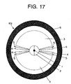
- Fig. 17 is a top plan view showing the makeup of a microactuator using a rotationally driven, electrostatic impact driving mechanism in the fourth embodiment of the present invention.
- a microactuator M2 using this electrostatic impact driving mechanism comprises a pair of fan-shaped movable mass members 3 supported from a fixing member 1 positioned at the center by elastic support beams 2, respectively, each pair of driving electrodes 4 circumferentially juxtaposed spacedly with each of the movable mass members 3, each stopper member disposed between each driving electrode 4 and each movable mass member 3, and an outer frame part 6 that supports the fixing member 1, the driving electrodes 4 and the stopper members 5 and surrounds therewith the outsides of these members.
- the elastic support beams 2 may be weak in elasticity.
- a power supply circuit not shown is connected across each pair of movable mass members 3 and driving electrode 4, respectively.
- the entire body of the actuator M2 may pivotally be supported on a platform not shown. And now, turning ON and OFF the switch in each power supply circuit causes the corresponding movable mass member 3 to rotate clockwise or counterclockwise and then to come to collision with the stopper member 5, thereby generating a kinetic energy sufficient to move the actuator M2 clockwise.
- Fig. 18 is a view showing the makeup of a microactuator using a "bell-ringer” or “bell-striker” driving type electrostatic impact driving mechanism.
- a microactuator M 3 using this electrostatic mechanism comprises an outer frame part 6, a movable mass member 3 suspended and thereby supported from the outer frame part 6 with elastic support beams 2 usually made of obliquely parallel springs, a driving electrode 4 disposed below the movable mass member 3 and spacedly juxtaposed therewith, and a stopper member 5 disposed ahead of the movable mass member 3 and spacedly juxtaposed therewith, wherein the elastic support beams 2, the movable mass member 3, the driving electrode 4 and the stopper member 5 are accommodated in the outer frame part 6.
- the elastic support beams 2 may be weak in elasticity but should as they are inclined be strong or rigid enough to hold the movable mass member 3 in position.
- a power supply circuit 9 comprising a power supply 7 and a switch is connected to the driving electrode 4 and to the movable mass member 3 via the outer frame part 6 and the elastic support beams 2. Also, the entire body of the actuator 3 is mounted on a platform 10. And now, turning ON and OFF the switch 8 in the power supply circuit 9 will, as shown in Fig. 19, cause the movable mass member 3 to be attracted towards the driving electrode 4 but a horizontal component of the attraction in this embodiment to move the movable mass member 3 towards the stopper member 5 and thus to bring the former into collision with the latter, thereby producing a kinetic energy sufficient to move the actuator M3 horizontally on the platform 10.
- Fig. 20 is a top plan view of a one-dimensionally driven microactuator in the sixth embodiment using an electrostatic impact driving mechanism in which a fixing member serves also as a stopper
- Fig. 21 is a cross sectional view of the microactuator taken along the line A-A in Fig. 20.
- a microactuator M4 using this electrostatic impact driving mechanism includes a pair of elastic support beams 2.
- each of the elastic support beams 2 comprises four (4) thin elastic plates 2a, 2b, 2c and 2d, and a thin elastic plate 2e having one end of each of these thin elastic plates securely connected thereto for supporting them parallel to one another, wherein of them the outer thin elastic plates 2a and 2d have the other ends are securely connected to fixing ends 1a and 1'a of fixing elements 1 and 1' and the inner thin elastic plates 2b and 2c have the other ends securely connected to a movable mass member 3.
- the fixing elements 1 and 1' are monolithic with the outer frame part 6, having arms 1b and 1'b extending parallel to sides of the movable mass member 3 and being united to the outer frame part 6.
- the makeup of this microactuator is otherwise identical to that of the first embodiment.
- each elastic support beam 2 supported by two fixing elements 1 and 1' provides an increased mechanical strength and an improved reliability for the microactuator.
- the fixing elements 1 and 1' serve as stopper members.
- Fig. 22 is a top plan view of a microactuator in the seventh embodiment using an electrostatic impact driving mechanism in which a driving electrode 4 is split.
- a microactuator M5 using this electrostatic impact driving mechanism includes four (4) independent power supplies 9a, 9b, 9c and 9d, which are adapted to energize four driving electrodes 4a, 4b, 4c and 4d , respectively, independently of one another.
- the makeup of this microactuator is otherwise identical to those of the other embodiment.
- This makeup utilizes a torsion effect of the elastic support beams and thereby allows the microactuator to be advanced in a selected direction alterable, by energizing one of the electrodes selected.
- a microactuator that is extremely small in size. Especially, provided in its driving source with a movable mass member adapted to be driven electrostatically, a self-driven impact actuator is obtained that is enhanced in environmental reliability.
- the present invention also provides a method of manufacture utilizing a bulk micromachining technique, which permits manufacturing at an extremely high precision and, without the need to assemble individually, at an extremely reduced cost.
Landscapes
- Micromachines (AREA)
Abstract
An extremely small, self-moved, impact driven microactuator
is disclosed that has a movable mass member electrostatically driven
and which eliminates the need for it to be assembled individually. The
microactuator includes a fixing member (1) securely connected to a
pedestal part (14), an elastic support beam member (2) having one end
securely connected to the fixing member, a movable mass member (3)
fastened to the other end of the elastic support beam member, a driving
electrode and a stopper member (4, 5) each securely connected to the
pedestal part and spacedly juxtaposed with the movable mass member,
and a power supply circuit (9) for applying a voltage between the
movable mass and driving electrode members. In operation, turning the
power supply circuit ON generates electrostatic attraction between the
driving electrode member and movable mass members, thereby
bringing the movable member into collision with the stopper member,
followed by the transmission of a kinetic energy then produced to the
outer frame part, and subsequently turning the power supply circuit
OFF removes the electrostatic attraction, thereby permitting the
movable mass member to return to its original position under an elastic
force exerted by the elastic support beam member, followed by the
transmission of a reaction force then produced to outer frame part,
whereby the microactuator is bodily moved in a given direction.
Description
The present invention relates to a micro-actuator and in
particular to a microactuator using an electrostatic impact driving
mechanism, and to a method of making such a microactuator.
Precision positioning techniques required in carrying out a
micromachining or a micro-displacement operation has come to be
ranked to take a very important position, and are sought to be higher in
precision than ever.
Making good use of micromachining technologies for
manufacturing a positioning device allows its bulk production in a
batch process, and has an advantage of eliminating the need to assemble
each device product individually while yielding products small-sized, at
a low cost and with a reduced individual difference. For this reason,
recent years have seen extensive researches conducted on various
microactuators and microsystems for positioning (see M. Steven
Rodger et al, "Intricate Mechanisms-on-a-chip Enabled by 5-Level
Surface Micro Machining", Digest of Transducers '99, Sendai, Japan,
June 1999, pp. 990- 993). Faced with the problem of importance that
the force produced is unsatisfactory and that the movable distance is
insufficient, however, micro-actuators so far proposed have had a
limited extent of their applicability. For example, an impact driving
mechanism using a piezoelectric element has been proposed (see
Toshiro Higuchi, Masahiro Watanabe, Ken-ichi Watanabe,
"Ultra-precision Positioning Mechanism utilizing Rapid Deformation of
a Piezoelectric Element", Journal of the Society of Precision
Engineering, 54-11, 2107 (1998), which using a frictional force and an
piezoelectric element, has both a very small displacement in a
nanometer range and a movable distance utmost minimum in principle,
but needs to be built up individually and has a limitation in
miniaturization.
Further, microactuators so far proposed are poor in reliability
measure such as to prevent entry of dust and moisture in air and are
thus inferior in environmental reliability.
It is accordingly a first object of the present invention to
provide a microactuator that eliminates the need to assemble
individually and can be miniaturized much more than ever and, in
particular, to provide a self-moved impact driven actuator which with
an electrostatically driven, movable mass member in its driving source
is high in environmental reliability. It is a second object of the present
invention to provide a method of making such a microactuator utilizing
a bulk micromachining technique.
In order to achieve the first object mentioned above, there is
provided in accordance with the present invention a microactuator with
an electrostatic impact driving mechanism, which as set forth in claim 1
in the appended claims comprises: a closed receptacle formed of an
outer frame part, a pedestal part and a lid part; an elastic support beam
member disposed in the said closed receptacle; a fixing member
disposed in the said closed receptacle and securely connecting a first
end of the said elastic support beam member to the said pedestal part; a
movable mass member disposed in the said closed receptacle and
securely connected to a second end of the said elastic support beam
member; a driving electrode and a stopper member disposed in the said
closed receptacle, each of which is securely connected to the said
pedestal part and spacedly juxtaposed with the said movable mass
member; and a power supply circuit disposed in the inside or the
outside of the said closed receptacle for applying a voltage between the
said movable mass and driving electrode members, wherein the
microactuator is so operable that turning the said power supply circuit
ON generates electrostatic attraction between the said driving electrode
and movable mass members, thereby bringing the said movable member
into collision with the said stopper member, followed by the
transmission of a kinetic energy then produced to the said closed
receptacle, and subsequently turning the said power supply circuit OFF
removes the said electrostatic attraction, thereby permitting the said
movable mass member to return to its original position under an elastic
force exerted by the said elastic support beam member, followed by the
transmission of a reaction force then produced to the said closed
receptacle, whereby an entire body of the said microactuator is moved
in a given direction.
The microactuator so constructed with the electrostatic driving
mechanism is of a structure that can be built up by an integrated circuit
process technology, and which permits the components to be integrated
into an identical device, which eliminates the need to fabricate
individual components, and which allows the product to be made that is
extremely small in size
Specifically, the microactuator with the electrostatic impact
driving mechanism may as set forth in claim 2 in the appended claims
be characterized in that the said first end of the said elastic support
beam member is securely connected to a single fixing element
constituting the said fixing member, the said movable mass member is
securely connected to the said second end of the said elastic support
beam member at two places thereon, the said single fixing element is
disposed so as to make the said movable mass member capable of
rocking over a surface of the said pedestal part, the said driving
electrode and stopper members comprise a first and a second driving
electrode and a first and a second stopper member, wherein the said
first driving electrode and stopper element are each disposed in front of
the said movable mass member while the said second driving electrode
and stopper elements are each disposed in rear of the said movable
mass member, and the said voltage is applied between a said driving
electrode and the said movable mass member via the said outer frame
part.
In this construction of the microactuator, selecting the first or
second drive electrode with which the voltage is applied allows the
microactuator to be bodily moved forth or back.
Alternatively, the microactuator with the electrostatic impact
driving mechanism may as set forth in claim 3 in the appended claims
be characterized in that the said elastic support beam member is capable
of elastically supporting the said movable mass member in two axial
directions perpendicular to each other, the said elastic support beam
member has a pair of first ends securely connected, respectively, to two
fixing elements constituting the said fixing member, the said second
end of the said elastic support beam member is securely connected at
one place to the said movable mass member, the said two fixing
elements are arranged so as to make the said movable mass member
capable of rocking forth and back and right and left over a surface of
the said pedestal part, the said driving electrode and said stopper
members comprise a first, a second, a third and a fourth driving
electrode and a first, a second, a third and a fourth stopper element,
wherein the said first driving electrode and stopper member, the said
second driving electrode and stopper member, the said third driving
electrode and stopper element and the said fourth driving electrode and
stopper element are disposed in front of, in rear of, at a right hand side
and at a left hand side, of the said movable mass member, respectively,
and the said voltage is applied between a said driving electrode and the
said movable mass member via the said outer frame part.
This construction permits the microactuator to be bodily
moved two dimensionally in a given plane and to be so moved in any
direction as desired.
Alternatively, the microactuator with the electrostatic impact
driving mechanism may as set forth in claim 4 in the appended claims
be characterized in that the said movable mass member is fan-shaped
and securely connected to the said second end of the said elastic
support beam member, the said first end of said elastic support beam
member is securely connected to the said fixing member, the said fixing
member is arranged so as to make the said movable mass member
capable of rocking about the said fixing member over a surface of the
said pedestal part, the said driving electrode member and the said
stopper member are each fan-shaped, and the said voltage is applied
between the said driving electrode member and the said movable mass
member via the said outer frame part.
In this construction, the microactuator is rotationally driven
and may be applied to form a motor or the like.
Alternatively, the microactuator with the electrostatic impact
driving mechanism may as set forth in claim 5 in the appended claims
be characterized in that the said movable mass member is supported in
suspension by the said elastic support beam member which obliquely
support it, the said driving electrode member is disposed below the said
movable mass member, the said stopper member is disposed in front or
in rear of the said movable mass member, and the said voltage is
applied between the said driving electrode member and the said
movable mass member via the said outer frame part.
This construction of the microactuator utilizing a potential
energy of gravity as the additional force provides a driving force larger
in magnitude.
Alternatively, the microactuator with the electrostatic impact
driving mechanism may as set forth in claim 6 in the appended claims
be characterized in that the elastic support beam member has a pair of
first ends securely connected, respectively, to two fixing elements
constituting the said fixing member, the said second end of the said
elastic support member is securely connected at one place thereon to
the said movable mass member, the said two fixing elements are
arranged so as to make the said movable mass member capable of
rocking over a surface of the said pedestal part and are disposed in
front and in rear of the said driving electrode and movable mass
members, and the said voltage is applied between the said driving
electrode member and the said movable mass member via the said outer
frame part.
Advantageously, the said two fixing elements may be
monolithic with the said outer frame part as set forth in claim 7 in the
appended claims
This construction of the microactuator in which two fixing
elements are used to fasten the elastic support beam member thereto
allows the latter to be fixed to the outer frame part with an increased
firmness and provides an improved reliability for the microactuator.
Also, advantageously the fixing elements here serve as stopper
members and are monolithic with the outer frame part. Thus, when the
movable mass member comes into collision with the fixing elements
(stopper members), electric charges on the movable mass member are
advantageously transferred to the fixing elements and then absorbed by
the power supply via the outer frame part. Consequently, there is no
charge accumulation on the stopper members; hence there ensues a
stabilized operation.
Preferably, the microactuator with the electrostatic impact
driving mechanism as set forth in claim 8 in the appended claims is
characterized in that the said movable mass member is securely
connected to a pair of such elastic support beam members as aforesaid,
which are in turn securely connected to a pair of such fixing members
as aforesaid, respectively.
This construction of the microactuator permits the movable
mass member to be supported as well-balanced in a horizontal plane
and hence to be rocked stably and smoothly there.
Preferably, the microactuator with the electrostatic impact
driving mechanism as set forth in claim 9 in the appended claims is
characterized in that the said driving electrode member is split into two
driving electrode elements, which are energizable independently of
each other.
This construction of the microactuator utilizes a torsion effect
of the elastic support beam members and thereby allows the
microactuator to be advanced in a selected direction alterable, by
applying a voltage only to one of the electrodes selected.
Also, the microactuator with the electrostatic impact driving
mechanism may as set forth in claim 10 in the appended claims be
characterized in that the said outer frame part is composed of Si single
crystal, and the said pedestal and lid parts are composed of a material
having a preselected friction coefficient.
Also, the microactuator with the electrostatic impact driving
mechanism may as set forth in claim 11 in the appended claims be
characterized in that the said material having a preselected friction
coefficient is pyrex glass.
Also, the microactuator with the electrostatic impact driving
mechanism may as set forth in claim 12 in the appended claims be
characterized in that the said outer frame part, the said elastic support
beam member, the said movable mass member, the said driving
electrode member and the said stopper member are composed of a Si
single crystal, and the said pedestal and lid parts are composed of a
material having a preselected friction coefficient.
Also, the microactuator with the electrostatic impact driving
mechanism may as set forth in claim 13 in the appended claims be
characterized in that the said outer frame part is composed of Si single
crystal, and the said pedestal and lid parts are composed of a material
having a preselected friction coefficient.
Also, the microactuator with the electrostatic impact driving
mechanism may as set forth in claim 14 in the appended claims be
characterized in that the said material having a preselected friction
coefficient is pyrex glass.
The present invention also provides a linear driving stage,
which may as set forth in claim 15 in the appended claims comprise: a
fixed platform; a movable platform slidably mounted on the said fixed
platform; and a microactuator with an electrostatic impact driving
mechanism as set forth in any one of claims 1 to 12, or a microactuator
as set forth in claim 13, the said microactuator being fastened to the
said movable platform.
The present invention also provides a linear X-Y driving stage,
which may as set forth in claim 16 in the appended claims comprise: a
fixed platform; a first movable platform slidably mounted on the said
fixed platform for movement in a first direction; a second movable
platform slidably mounted on the said first movable platform for
movement in a second direction orthogonal to the said first direction;
and a microactuator with an electrostatic impact driving mechanism as
set forth in any one of claims 1 to 12, or a microactuator as set forth in
claim 13, the said microactuator being fastened to the said second
movable platform.
The invention also provides a drive unit which as set forth in
claim 17 in the appended claims comprises a movable body and a
plurality of microactuators using electrostatic impact driving
mechanism incorporated therein, each of which is a microactuator as set
forth in any one of claims 1 to 12 or a microactuator as set forth in
claim 13.
In order to achieve the second object mentioned above,
there is also provided in accordance with the present invention
a method of making a microactuator with an electrostatic
impact driving mechanism, by monolithically forming from a
Si single crystal substrate, an outer frame part, and an elastic
support beam, a movable mass, a driving electrode and a
stopper member, and forming a pedestal part and a lid part
from a material having a preselected friction coefficient, which
method as set forth in claim 18 in the appended claims is
characterized by comprising the steps of: a) forming the said
driving electrode member on a front surface of the said Si
single crystal substrate; b) etching the said Si substrate from
its back side in order to make the said elastic support beam
and movable mass members floating in the air; c) attaching a
first member having a preselected friction coefficient to rear
surfaces of the said Si substrate; d) etching the said Si
substrate from its front side in order to form the said outer
frame part, the said elastic support beam, movable mass
members, the said driving electrode member and the said
stopper member monolithically; e) etching the said Si
substrate from its front side in order to make the said elastic
support beam and movable mass members floating in the air;
and f) attaching a second member having the said preselected
friction coefficient to front surfaces of the said Si substrate.
The method of making a microactuator with an electrostatic
impact driving mechanism may as set forth in claim 19 in the appended
claims be specifically characterized in that etching steps b), d) and e)
are carried out each by inductively coupled plasma - reactive etching.
Also, the method of making a microactuator with an
electrostatic impact driving mechanism may as set forth in claim 20 in
the appended claims be specifically characterized in that steps c) and f)
in which a first or second member having the preselected friction
coefficient is attached to rear or front surfaces of the Si substrate are
carried out each by anodic joining of pyrex glass as the first or second
member to said Si substrate.
The present invention will better be understood from the
following detailed description and the drawings attached hereto
showing certain illustrative embodiments of the present invention. In
this connection, it should be noted that such embodiments illustrated in
the accompanying drawings hereof are intended in no way to limit the
present invention but to facilitate an explanation and understanding
thereof. In the drawings:
Now, an explanation in detail is given in respect of a first form
of embodiment in a microactuator and a method of its manufacture.
Fig. 1 is a plan view illustrating the makeup of a microactuator
using an electrostatic impact driving mechanism in the first
embodiment of the present invention and Fig. 2 is a cross sectional
view of the microactuator taken along the line A-A in Fig. 1
It should be noted that Fig. 1 shows the inside makeup of the
microactuator and its lid part is omitted from illustration.
This microactuator M using an electrostatic impact driving
mechanism is made up of a movable mass member 3 supported by a
pair of elastic support beams 2 and a pair of fixing members 1, a pair of
(first and a second) driving electrodes 4 disposed in front and in rear of
the movable mass member 3, respectively, a pair of (first and second)
stopper members 5 disposed at two opposite sides of each electrode 4,
and a closed receptacle for hermetically sealing the fixing members 1,
the driving electrodes 4, the stopper members 5 and the members
mentioned above.
The closed sealing receptacle is made up of an outer frame part
6 formed of a Si single crystal substrate, a pedestal part 14, and a lid
part 16.
Further, each of the elastic support beams 2 comprises four
thin elastic plates 2a, 2b, 2c and 2d, and a thin elastic plate 2e having
one end of each of these thin elastic plates securely connected thereto
for supporting these thin elastic plates parallel to one another. The
outer thin elastic plates 2a and 2d have their other ends securely
connected to the movable mass member 3 while the inner thin elastic
plates 2b and 2c have their other ends securely connected to the
opposite ends 1a and 1'a of the fixing member 1, respectively.
It should be noted here that the elastic support beams 2 and 2
may be weak in elasticity. Further, a power supply circuit 9 comprising
a power supply 7 and a switch 8 is connected between the movable
mass member 3 and one of the (first) driving electrodes 4. This power
supply circuit 9 may be disposed either outside or inside of the
receptacle. Also, another (second) power supply circuit 9' comprising a
power supply 7' and a switch 8' is connected between the. movable
mass member 3 and the other (second) driving electrode 4. And, the
entire actuator M is mounted on a platform 10 for self-driving thereon.
Here, the pedestal part 14 and the lid part 16 can be formed,
preferably, of pyrex glass.
Mention is next made of the principles of operation of the
microactuator using the electrostatic impact driving mechanism in the
first embodiment of the invention.
Figs. 3 to 6 are conceptual views used to illustrate the
principles of operation of the microactuator of the present invention. It
should be noted here that for the sake of facilitating the illustration, the
second electrode 4, the second stopper member 5 and the second power
supply 9' are not shown. One end of the power supply circuit 9 is
shown connected to the movable mass member 3 via the outer frame 6
and the elastic support beam (spring) 2.
First, the switch 8 of the power supply circuit 9 disposed
outside of the outer frame 6 is turned ON, as shown in Fig. 4, to apply a
voltage across a spacing between the driving electrode 4 and the
movable mass member 3 from the power supply 8. Then, an
electrostatic force is generated across the spacing between the movable
mass member 3 and the driving electrode 4, thereby causing the
movable mass member 3 to begin moving towards the driving electrode
4 and then to be slowly accelerated. It should be noted here that the
reaction force generated in the direction opposite to the direction of
acceleration, namely the force which the actuator M receives from the
platform 10 is set not to exceed the static frictional force between the
actuator M and the platform 10.
Then, the movable mass member 3 will continue to be
accelerated until it comes into collision with the stopper members 5.
Concurrently with the collision, the kinetic energy of the movable mass
member 3 is transmitted to the entire body of the actuator M, and the
actuator M is bodily moved upon the transmitted energy or force
exceeding the static frictional force with the platform 10. And, the
actuator M continues to move until the kinetic energy it acquired from
the movable mass member 3 is lost by the dynamic frictional force
between the actuator M and the platform 10 and then comes to a halt.
Referring next to Fig. 6, turning the switch 8 in the power
supply circuit 9 OFF to make the applied voltage nil causes the
movable mass member 3 to return to its original position under the
force exerted by the elastic support beams 2. When the movable mass
member 3 so returns, the reaction force then generated, namely the
reaction force which the actuator M receives from the platform 10, is
directed in the direction of advance of the actuator M and hence
contributes to the movement of the actuator M in the direction of its
advance. Repeating the cycle mentioned allows the actuator M to be
self-moved or -driven in one direction. It is a matter of course that
repeating the ON-OFF of the voltage applied across the second driving
electrode 4 and the movable mass member 3 from the power supply
circuit 9' not shown in Figs. 3 to 6 allows the movable mass member 3
to be self-moved or -driven in the opposite direction. The power supply
circuits 9 and 9' may alternatively be disposed inside of the closed
actuator receptacle.
In the above embodiment, adding a mechanism adapted to
effect electrostatic or magnetic attraction to the pedestal part 14 or the
lid part 16 allows movement on a vertical wall or a ceiling. Further, the
friction may be caused to occur between the actuator M and the
platform 10 not by the actuator's own weight but by a weight of a bias
spring.
Mention is next made of a method of making an actuator of the
present invention by taking an example of making a microactuator
using the electrostatic impact driving mechanism in the first
embodiment thereof.
While this example is shown omitting the stopper members
unlike the microactuator makeup shown in Fig. 1, the process of
manufacture equally applies to that makeup.
Fig. 7 illustrates the process of manufacturing the first
embodiment of the present invention. It should be noted here that in Fig.
7, each of the views shown at the left hand side corresponds to the cross
section taken along the line A-A in Fig. 1 and each of the views shown
at the right hand side corresponds to the cross section taken along the
line B-B in Fig. 1. An actuator being made here has a structure obtained
in the manner that in the interest of making the mass of the movable
mass member 3 greater, the movable mass member 3 and the fixing
member 1 are first micromachined from a Si (silicon) substrate by
etching the substrate from the front side surface to the back side surface,
and then the fixing member 1 and the driving electrodes 4 are joined to
a pyrex glass plate becoming the pedestal part 14.
First, as shown in Fig. 7 at (a) the Si substrate 11, which is
high in conductivity and of a thickness of 225 micrometers, has an Al
(aluminum) layer 12 built up thereon. Then, by using a first photomask
(not shown), patterning is effected of the Al layer 12 for forming an
electrode. Next, as shown in Fig. 7 at (b) a resist layer 13 is applied to
the back of the substrate, and patterning is effected of the resist layer
by using a second photomask (not shown) to bring the movable mass
member into the state that it floats in the air. And, in order to bring the
movable mass member into the state that it floats in the air, as shown in
Fig. 7 at (c) with the resist layer 13 used as the mask the substrate is
subjected from its back to a first ICP-RIE (inductively coupled plasma
- reactive ion etching step). Those portions of the Si substrate 11 which
are becoming the outer frame 6 are then left with the resist thereon and
therefore not etched.
Thereafter, as shown in Fig. 7 at (d) the resist layer 13 is
removed, and as shown in Fig. 7 at (e) the pyrex glass plate becoming
the pedestal part 14 is joined by anodic joining to the Si substrate 11
and resist layers 15 are applied to the surface of the substrate 11 and
the Al layer 12, followed by patterning thereof such as to
monolithically form the Si substrate 11 portions becoming the outer
frame part, the elastic support beams 2 and the movable mass member
3.
And, as shown in Fig. 8 at (a) by using the patterned resist
layers 12 as the masks a second ICP-RIE process step is carried out
from the front side. Subsequently, as shown in Fig. 8 at (b) the
patterned resists are removed, and as shown in Fig. 8 at (c) a third
ICP-RIE process step is performed from the front side to dig the
substrate down, thereby forming the elastic support beams 2 and the
movable mass member 3 so that they lie out of contact with the lid part
16, namely they lie floating in the air. Those portions of the Si substrate
11 and the fixing member 1 on which Al remain to lie are not etched.
Finally, as shown in Fig. 8 at (d) a pyrex glass plate becoming the lid
part 16 is joined to the Al layers 12 by anodic joining (a method of
joining in which pyrex glass is brought into contact with Si and an
elevated electric field is applied between the pyrex glass plate and the
Si substrate), or otherwise with an adhesive agent. In this manner, the
microactuator using the electrostatic impact driving mechanism is
finished up.
It should be noted here that normally a plurality of
microactuator units are concurrently fabricated and cut by a dicing saw
into chips as individual microactuator products.
The method of manufacture described above uses a highly
advanced Si integrated circuit process technology and hence allows
mass production of microactuators of a given design and size in a lump
with their constituent elements such as the movable mass member,
elastic support beams and driving electrodes integrated with precision.
Thus, it permits such microactuators to be produced at a reduced cost
and with a minimum individual difference.
This method of manufacture also eliminates the need to
fabricate and adjust the individual components and permits making
them extremely small in size.
Further, this method of manufacture permits a microactuator to
be formed in an enclosed structure having its top and bottom formed of
pyrex glass and its sides formed of silicon crystal, and hence free from
entry of dust and moisture, high in environmental reliability and with
an extended service life.
Two microactuators are made by the method of manufacture,
one having the elastic support beams of 500 micrometers long and the
other having those of 600 micrometers long. These microactuators are
shown to have their driving voltages of 70 and 20 volts required to
bring the mass member 3 into collision with the stopper members and
their resonant frequencies of 368 Hz and 100 Hz, respectively. Figs.
22A and 22B are the electron microscope photographs of such
microactuators used in such measurements.
Mention is next made of a second embodiment of the
invention.
Fig. 9 is a decomposed perspective view of the second
embodiment of the present invention. A movable platform 17 formed in
its lower surface with V-shaped recesses 17a by anisotropic etching is
placed on a fixed platform 18 formed in its upper surface with a
V-shaped projections 18a by anisotropic etching so that with the
V-shaped recesses 17a fitted on the V-shaped projections 18a the upper
platform 17 may be slidably moved over the fixed platform, thereby to
making up a linear driving stage 19. The movable platform 17 has a
one-dimensionally driven impact microactuator M fastened to its upper
surface, which enables the movable platform 17 to be moved on the
fixed platform 18 in the directions indicated by the arrows. It should be
noted here that the actuator M is basically of the structure which as
shown in Fig. 10 and in Fig. 11 that is a cross sectional view thereof
taken along the line A-A, is the same as in the first embodiment
described above; hence its repeated description in detail is omitted. It is
shown, however, that the lid part 16 is formed with a through-hole 20
for wiring such that the driving electrodes 4, the fixing member 1 of the
movable mass member 3 and the outer frame part 6 may have an
voltage applied thereto or may otherwise be grounded.
Mention is next made of a third embodiment of the invention.
Fig. 12 is a decomposed perspective view showing the third
embodiment of the present invention. Here, an X-direction movable
platform 21 formed in its lower surface with V-shaped recesses 21a by
anisotropic etching, a Y-direction movable platform 22 formed in its
upper surface with V-shaped projections 22a and in its lower surface
with V-shaped recesses 22b perpendicular thereto by anisotropic
etching, and a fixed platform 23 formed in its upper surface with
V-shaped projections 23a by anisotropic etching are assembled together
so that with the V-shaped recesses 21a fitted with the V-shaped
projections 22a and the V-shaped recesses 22b fitted with the V-shaped
projections 23a the platform 21 may be slidably moved on the platform
22 and the latter may be slidably moved on the platform 23, thereby
making up an XY driving stage 24. The X-direction movable platform
21 has a two-dimensionally driven impact microactuator M1 fastened to
its upper surface, which enables the X-direction movable platform 21 to
be moved on the Y-direction movable platform 22 in a X-direction
indicated by the arrow and the Y-direction movable platform 22 to be
moved on the fixed platform 23 in a Y-directions indicated by the
arrow.
The basic makeup of this actuator M1 is shown in Fig. 13 and
in Fig. 14 that is a cross sectional view thereof taken along the line A-A.
The microactuator M1 comprises a movable mass member 3 supported
by a pair of T-shaped elastic support beams 2 fixed to fixing elements 1
disposed at four corners in the closed receptacle, two pairs of driving
electrodes 4 spacedly juxtaposed with the movable mass member 3 at
its front and back sides and at its right and left hand sides, respectively,
each pair of stopper members 5 disposed at opposite sides of each
driving electrode 4, respectively, and an outer frame part 6 made from a
Si substrate and having side walls which support and surround
therewith the fixing elements 1, the driving electrodes 4 and the stopper
members 5. Also, there is connected to each driving electrode 4 and the
movable mass member 3, respectively, a power supply circuit such that
turning its switch ON and OFF generates a kinetic energy sufficient to
move the actuator M1 in the X- , Y-direction. For example, applying a
voltage between one of the front and back side driving electrodes 4 and
the movable mass member 3 while concurrently removing a voltage
between one of the right and left hand side driving electrodes 4 and the
movable mass member 3 generates a kinetic energy that moves the
actuator M1 diagonally or at an angle. Thus, the actuator M1 is
movable by the single device in any direction as desired in a
two-dimensional plane. It should be noted further that the lid part 16
(as shown) or the pedestal part 14 is formed with a wiring through-hole
20 such that the driving electrodes 4, fixing members 1 of the movable
mass member 3 and side walls of the outer frame part 6 may have an
voltage applied thereto or may otherwise be grounded. It should also be
noted that in the second and third embodiments mentioned above, the
recesses formed in the movable platforms 17, 21 and the projections
formed on the fixed platforms 18 (22) may be dovetail grooves 17c
(21c) and dovetails 18c (22c), respectively, as shown in Fig. 15.
Also, as shown in Fig. 16 a plurality of actuators M or M1 may
be fixed in position in a movable body 25 to provide a drive unit larger
in size. Further, incorporating into the movable body 25 a plurality of
one-dimensionally movable actuators M with the directions of their
movements set three-dimensionally therein makes it movable
three-dimensionally. The movable body 25 is also made movable
three-dimensionally by incorporating into it a combination of
one-dimensional and two-dimensional actuators M and M1. Further, a
displacement of a stage as mentioned above is made detectable by
integrating a displacement sensor therein, e.g., incorporating a
capacitance type sensor in a slide surface or notching such a surface for
reading by an optical encoder.
Mention is next made of a fourth embodiment of the invention.
Fig. 17 is a top plan view showing the makeup of a
microactuator using a rotationally driven, electrostatic impact driving
mechanism in the fourth embodiment of the present invention.
A microactuator M2 using this electrostatic impact driving
mechanism comprises a pair of fan-shaped movable mass members 3
supported from a fixing member 1 positioned at the center by elastic
support beams 2, respectively, each pair of driving electrodes 4
circumferentially juxtaposed spacedly with each of the movable mass
members 3, each stopper member disposed between each driving
electrode 4 and each movable mass member 3, and an outer frame part
6 that supports the fixing member 1, the driving electrodes 4 and the
stopper members 5 and surrounds therewith the outsides of these
members. It should be noted here that the elastic support beams 2 may
be weak in elasticity. Further, a power supply circuit not shown is
connected across each pair of movable mass members 3 and driving
electrode 4, respectively. Also, the entire body of the actuator M2 may
pivotally be supported on a platform not shown. And now, turning ON
and OFF the switch in each power supply circuit causes the
corresponding movable mass member 3 to rotate clockwise or
counterclockwise and then to come to collision with the stopper
member 5, thereby generating a kinetic energy sufficient to move the
actuator M2 clockwise.
Mention is next made of a fifth embodiment of the invention.
Fig. 18 is a view showing the makeup of a microactuator using
a "bell-ringer" or "bell-striker" driving type electrostatic impact
driving mechanism.
A microactuator M 3 using this electrostatic mechanism
comprises an outer frame part 6, a movable mass member 3 suspended
and thereby supported from the outer frame part 6 with elastic support
beams 2 usually made of obliquely parallel springs, a driving electrode
4 disposed below the movable mass member 3 and spacedly juxtaposed
therewith, and a stopper member 5 disposed ahead of the movable mass
member 3 and spacedly juxtaposed therewith, wherein the elastic
support beams 2, the movable mass member 3, the driving electrode 4
and the stopper member 5 are accommodated in the outer frame part 6.
It should be noted here that the elastic support beams 2 may be weak in
elasticity but should as they are inclined be strong or rigid enough to
hold the movable mass member 3 in position. Further, a power supply
circuit 9 comprising a power supply 7 and a switch is connected to the
driving electrode 4 and to the movable mass member 3 via the outer
frame part 6 and the elastic support beams 2. Also, the entire body of
the actuator 3 is mounted on a platform 10. And now, turning ON and
OFF the switch 8 in the power supply circuit 9 will, as shown in Fig. 19,
cause the movable mass member 3 to be attracted towards the driving
electrode 4 but a horizontal component of the attraction in this
embodiment to move the movable mass member 3 towards the stopper
member 5 and thus to bring the former into collision with the latter,
thereby producing a kinetic energy sufficient to move the actuator M3
horizontally on the platform 10.
Mention is next made of a sixth embodiment of the invention.
Fig. 20 is a top plan view of a one-dimensionally driven
microactuator in the sixth embodiment using an electrostatic impact
driving mechanism in which a fixing member serves also as a stopper,
and Fig. 21 is a cross sectional view of the microactuator taken along
the line A-A in Fig. 20.
A microactuator M4 using this electrostatic impact driving
mechanism includes a pair of elastic support beams 2. And, each of the
elastic support beams 2 comprises four (4) thin elastic plates 2a, 2b, 2c
and 2d, and a thin elastic plate 2e having one end of each of these thin
elastic plates securely connected thereto for supporting them parallel to
one another, wherein of them the outer thin elastic plates 2a and 2d
have the other ends are securely connected to fixing ends 1a and 1'a of
fixing elements 1 and 1' and the inner thin elastic plates 2b and 2c have
the other ends securely connected to a movable mass member 3. The
fixing elements 1 and 1' are monolithic with the outer frame part 6,
having arms 1b and 1'b extending parallel to sides of the movable mass
member 3 and being united to the outer frame part 6. The makeup of
this microactuator is otherwise identical to that of the first embodiment.
This makeup having each elastic support beam 2 supported by
two fixing elements 1 and 1' provides an increased mechanical strength
and an improved reliability for the microactuator. Also, the fixing
elements 1 and 1' serve as stopper members. Thus, when the movable
mass member 3 comes into collision with the fixing elements (stoppers),
electric charges on the movable mass member are advantageously
transferred to the fixing elements 1 and 1' and then absorbed by the
power supply via the outer frame part. Consequently, there is no charge
accumulation on the stopper members; hence there ensues a stabilized
operation.
Mention is next made of a seventh embodiment of the
invention.
Fig. 22 is a top plan view of a microactuator in the seventh
embodiment using an electrostatic impact driving mechanism in which
a driving electrode 4 is split.
A microactuator M5 using this electrostatic impact driving
mechanism includes four (4) independent power supplies 9a, 9b, 9c and
9d, which are adapted to energize four driving electrodes 4a, 4b, 4c and
4d , respectively, independently of one another. The makeup of this
microactuator is otherwise identical to those of the other embodiment.
This makeup utilizes a torsion effect of the elastic support
beams and thereby allows the microactuator to be advanced in a
selected direction alterable, by energizing one of the electrodes
selected.
Although the present invention has hereinbefore been set forth
with respect to certain illustrative embodiments thereof, it will readily
be appreciated to be obvious to a person skilled in the art that many
alterations thereof, omissions therefrom and additions thereto can be
made without departing from the essences of scope of the present
invention. Accordingly, it should be understood that the invention is
not intended to be limited to the specific embodiments thereof set forth
above, but to include all possible embodiments that can be made within
the scope with respect to the features specifically set forth in the
appended claims and to encompass all the equivalents thereof.
As set forth in the foregoing description, in accordance with
the present invention there is provided a microactuator that is extremely
small in size. Especially, provided in its driving source with a movable
mass member adapted to be driven electrostatically, a self-driven
impact actuator is obtained that is enhanced in environmental
reliability.
The present invention also provides a method of manufacture
utilizing a bulk micromachining technique, which permits
manufacturing at an extremely high precision and, without the need to
assemble individually, at an extremely reduced cost.
Claims (20)
- A microactuator using an electrostatic impact driving mechanism, comprising:wherein the microactuator is so operable that turning said power supply circuit ON generates electrostatic attraction between said driving electrode and movable mass members, thereby bringing said movable member into collision with said stopper member, followed by the transmission of a kinetic energy then produced to said closed receptacle, and subsequently turning said power supply circuit OFF removes said electrostatic attraction, thereby permitting said movable mass member to return to its original position under an elastic force exerted by said elastic support beam member, followed by the transmission of a reaction force then produced to said closed receptacle, whereby an entire body of said microactuator is moved in a given direction.a closed receptacle formed of an outer frame part, a pedestal part and a lid part;an elastic support beam member disposed in said closed receptacle;a fixing member disposed in said closed receptacle and securely connecting a first end of said elastic support beam member to said pedestal part;a movable mass member disposed in said closed receptacle and securely connected to a second end of said elastic support beam member;a driving electrode and a stopper member disposed in said closed receptacle, each of which is securely connected to said pedestal part and spacedly juxtaposed with said movable mass member; anda power supply circuit disposed in the inside or the outside of said closed receptacle for applying a voltage between said movable mass and driving electrode members,
- A microactuator using an electrostatic impact driving mechanism as set forth in claim 1, characterized in that said first end of said elastic support beam member is securely connected to a single fixing element constituting said fixing member, said movable mass member is securely connected to said second end of said elastic support beam member at two places thereon, said single fixing element is disposed so as to make said movable mass member capable of rocking over a surface of said pedestal part, said driving electrode and stopper members comprise a first and a second driving electrode and a first and a second stopper element, wherein said first driving electrode and stopper element are each disposed in front of said movable mass member while said second driving electrode and stopper elements are each disposed in rear of said movable mass member, and said voltage is applied between a said driving electrode and said movable mass member via said outer frame part.
- A microactuator using an electrostatic impact driving mechanism as set forth in claim 1, characterized in that said elastic support beam member is capable of elastically supporting said movable mass member in two axial directions perpendicular to each other, said elastic support beam member has a pair of first ends securely connected, respectively, to two fixing elements constituting said fixing member, said second end of said elastic support beam member is securely connected at one place to said movable mass member, said two fixing elements are arranged so as to make said movable mass member capable of rocking forth and back and right and left over a surface of said pedestal part, said driving electrode and said stopper members comprise a first, a second, a third and a fourth driving electrode and a first, a second, a third and a fourth stepper element, wherein said first driving electrode and stopper member, said second driving electrode and stepper member, said third driving electrode and stepper element and said fourth driving electrode and stepper element are disposed in front of, in rear of, at a right hand side and at a left hand side of said movable mass member, respectively, and said voltage is applied between a said driving electrode and said movable mass member via said outer frame part.
- A microactuator using an electrostatic impact driving mechanism as set forth in claim 1, characterized in that said movable mass member is fan-shaped and securely connected to said second end of said elastic support beam member, said first end of said elastic support beam member is securely connected to said fixing member, said fixing member is arranged so as to make said movable mass member capable of rocking about said fixing member over a surface of said pedestal part, said driving electrode member and said stopper member are each fan-shaped, and said voltage is applied between said driving electrode member and said movable mass member via said outer frame part.
- A microactuator using an electrostatic impact driving mechanism as set forth in claim 1, characterized in that said movable mass member is supported in suspension by said elastic support beam member which obliquely support it, said driving electrode member is disposed below said movable mass member, said stopper member is disposed in front or in rear of said movable mass member, and said voltage is applied between said driving electrode member and said movable mass member via said outer frame part.
- A microactuator using an electrostatic impact mechanism as set forth in claim 1, characterized in that said elastic support beam member has a pair of first ends securely connected, respectively, to two fixing elements constituting said fixing member, said second end of said elastic support member is securely connected at one place thereon to said movable mass member, said two fixing elements are arranged so as to make said movable mass member capable of rocking over a surface of said pedestal part and are disposed in front and in rear of said driving electrode and movable mass members, and said voltage is applied between said driving electrode member and said movable mass member via said outer frame part.
- A microactuator using an electrostatic impact mechanism as set forth in claim 6, characterized in that said two fixing elements are monolithic with said outer frame part.
- A microactuator using an electrostatic impact mechanism as set forth in any one of claims 1 to 7, characterized in that said movable mass member is securely connected to a pair of such elastic support beam members as aforesaid, which are in turn securely connected to a pair of such fixing members as aforesaid, respectively.
- A microactuator using an electrostatic impact mechanism as set forth in any one of claims 1 to 8, characterized in that said driving electrode member is split into two driving electrode elements, which are energizable independently of each other.
- A microactuator using an electrostatic impact mechanism as set forth in any one of claims 1 to 9, characterized in that said outer frame part is composed of Si single crystal, and said pedestal and lid parts are composed of a material having a preselected friction coefficient.
- A microactuator using an electrostatic impact mechanism as set forth in claim 10, characterized in that said material having a preselected friction coefficient is pyrex glass.
- A microactuator using an electrostatic impact mechanism as set forth in any one of claims 1 to 11, characterized in that said outer frame part, said elastic support beam member, said movable mass member, said driving electrode member and said stopper member are composed of Si single crystal, and said pedestal and lid parts are composed of a material having a preselected friction coefficient.
- A microactuator including a closed receptacle made of an outer frame part, a pedestal part and a lid part, characterized in that said outer frame part is composed of Si single crystal, and said pedestal and lid parts are composed of a material having a preselected friction coefficient.
- A microactuator as set forth in claim 13, characterized in that said material having a preselected friction coefficient is pyrex glass.
- A linear driving stage, comprising: a fixed platform; a movable platform slidably mounted on said fixed platform; and a microactuator using an electrostatic impact driving mechanism as set forth in any one of claims 1 to 12, or a microactuator as set forth in claim 13, said microactuator being fastened to said movable platform.
- A linear X-Y driving stage, comprising: a fixed platform; a first movable platform slidably mounted on said fixed platform for movement in a first direction; a second movable platform slidably mounted on said first movable platform for movement in a second direction orthogonal to said first direction; and a microactuator using an electrostatic impact driving mechanism as set forth in any one of claims 1 to 12, or a microactuator as set forth in claim 13, said microactuator being fastened to said second movable platform.
- A drive unit, comprising a movable body and a plurality of microactuators using electrostatic impact driving mechanism incorporated therein, each of which is a microactuator as set forth in any one of claims 1 to 12 or a microactuator as set forth in claim 13.
- A method of making a microactuator with an electrostatic impact driving mechanism, by monolithically forming from a Si single crystal substrate, an outer frame part, and an elastic support beam, a movable mass, a driving electrode and a stopper member and forming a pedestal part and a lid part from a material having a preselected friction coefficient, characterized by comprising the steps of:a) forming said driving electrode member on a front surface of said Si single crystal substrate;b) etching said Si substrate from its back side in order to make said elastic support beam and movable mass members floating in the air;c) attaching a first member having a preselected friction coefficient to rear surfaces of said Si substrate;d) etching said Si substrate from its front side in order to form said outer frame part, said elastic support beam and movable mass members, the formed portion of said driving electrode member and said stopper member monolithically;e) etching said Si substrate from its front side in order to make said elastic support beam and movable mass members floating in the air; andf) attaching a second member having said preselected friction coefficient to front surfaces of said Si substrate.
- A method of making a microactuator with an electrostatic impact driving mechanism, as set forth in claim 18, characterized in that etching steps b), d) and e) are carried out each by inductively coupled plasma-reactive etching.
- A method of making a microactuator with an electrostatic impact driving mechanism, as set forth in claim 18, characterized in that steps c) and f) in which a first or second member having the preselected friction coefficient is attached to rear or front surfaces of the Si substrate are carried out each by anodic joining of pyrex glass as the first or second member to said Si substrate.
Applications Claiming Priority (3)
| Application Number | Priority Date | Filing Date | Title |
|---|---|---|---|
| JP2000077105 | 2000-03-17 | ||
| JP2000077105 | 2000-03-17 | ||
| PCT/JP2001/002119 WO2001068512A1 (en) | 2000-03-17 | 2001-03-16 | Micro-actuator and method of manufacturing the actuator |
Publications (2)
| Publication Number | Publication Date |
|---|---|
| EP1270506A1 true EP1270506A1 (en) | 2003-01-02 |
| EP1270506A4 EP1270506A4 (en) | 2008-06-25 |
Family
ID=18594727
Family Applications (1)
| Application Number | Title | Priority Date | Filing Date |
|---|---|---|---|
| EP01912448A Withdrawn EP1270506A4 (en) | 2000-03-17 | 2001-03-16 | MICRO-ACTUATOR AND METHOD OF MANUFACTURING THE SAME |
Country Status (4)
| Country | Link |
|---|---|
| US (2) | US6774533B2 (en) |
| EP (1) | EP1270506A4 (en) |
| JP (1) | JP3831919B2 (en) |
| WO (1) | WO2001068512A1 (en) |
Cited By (1)
| Publication number | Priority date | Publication date | Assignee | Title |
|---|---|---|---|---|
| US6774533B2 (en) * | 2000-03-17 | 2004-08-10 | Japan Science And Technology Agency | Electrostatic impact driving microactuator |
Families Citing this family (21)
| Publication number | Priority date | Publication date | Assignee | Title |
|---|---|---|---|---|
| US6507138B1 (en) * | 1999-06-24 | 2003-01-14 | Sandia Corporation | Very compact, high-stability electrostatic actuator featuring contact-free self-limiting displacement |
| US6593666B1 (en) * | 2001-06-20 | 2003-07-15 | Ambient Systems, Inc. | Energy conversion systems using nanometer scale assemblies and methods for using same |
| US20040238907A1 (en) * | 2003-06-02 | 2004-12-02 | Pinkerton Joseph F. | Nanoelectromechanical transistors and switch systems |
| US7148579B2 (en) | 2003-06-02 | 2006-12-12 | Ambient Systems, Inc. | Energy conversion systems utilizing parallel array of automatic switches and generators |
| US7095645B2 (en) * | 2003-06-02 | 2006-08-22 | Ambient Systems, Inc. | Nanoelectromechanical memory cells and data storage devices |
| US7199498B2 (en) * | 2003-06-02 | 2007-04-03 | Ambient Systems, Inc. | Electrical assemblies using molecular-scale electrically conductive and mechanically flexible beams and methods for application of same |
| US7518283B2 (en) | 2004-07-19 | 2009-04-14 | Cjp Ip Holdings Ltd. | Nanometer-scale electrostatic and electromagnetic motors and generators |
| WO2007012028A2 (en) * | 2005-07-19 | 2007-01-25 | Pinkerton Joseph P | Heat activated nanometer-scale pump |
| JP4759735B2 (en) * | 2005-10-28 | 2011-08-31 | 国立大学法人 東京大学 | Drive actuator |
| EP1879214B1 (en) * | 2006-07-11 | 2011-10-12 | Canon Kabushiki Kaisha | Substrate for mass spectrometry, and method for manufacturing substrate for mass spectrometry |
| DE102006050188A1 (en) * | 2006-10-25 | 2008-04-30 | Robert Bosch Gmbh | Micromechanical component e.g. inertial sensor, has functional unit with functional surface comprising non-adhesive layer applied on regions, where layer is stable with respect to temperature of above specific value |
| WO2008124084A2 (en) * | 2007-04-03 | 2008-10-16 | Pinkerton Joseph F | Nanoelectromechanical systems and methods for making the same |
| US20090190254A1 (en) * | 2008-01-29 | 2009-07-30 | Seagate Technology Llc | Micromachined mover |
| FR2946970B1 (en) * | 2009-06-23 | 2011-07-15 | Commissariat Energie Atomique | MICROMECHANICAL DEVICE FOR AMPLIFYING VIBRATION MOVEMENT |
| JPWO2011102366A1 (en) * | 2010-02-16 | 2013-06-17 | 三洋電機株式会社 | Driving device and moving mechanism using the driving device |
| US10340818B2 (en) | 2013-08-08 | 2019-07-02 | National University Corporation Shizuoka University | Actuator, shutter device, fluid control device, switch, and two-dimensional scanning sensor device |
| WO2016114361A1 (en) * | 2015-01-16 | 2016-07-21 | 国立大学法人 東京大学 | Vibration power generation element |
| CN107360715B (en) * | 2015-03-25 | 2020-07-31 | 琳得科株式会社 | Apparatus for producing plate-like body with gas barrier layer |
| US9608082B2 (en) * | 2015-06-30 | 2017-03-28 | Infineon Technologies Ag | Electro-mechanical switching devices |
| US20210139314A1 (en) * | 2019-11-07 | 2021-05-13 | Innovative Interface Laboratory Corp. | Linear actuator |
| CN118598066B (en) * | 2024-04-30 | 2025-02-28 | 深圳瑞纳电子技术发展有限公司 | MEMS micro brake and manufacturing method thereof |
Family Cites Families (12)
| Publication number | Priority date | Publication date | Assignee | Title |
|---|---|---|---|---|
| JPS6060582A (en) * | 1983-09-13 | 1985-04-08 | 新技術事業団 | Minute moving method and device using impact force |
| JPS63299785A (en) * | 1987-05-29 | 1988-12-07 | Res Dev Corp Of Japan | Micro-movement device employing impact force of piezo-electric and electrostrictive element |
| US5049775A (en) * | 1988-09-30 | 1991-09-17 | Boston University | Integrated micromechanical piezoelectric motor |
| JPH0698584B2 (en) * | 1989-11-24 | 1994-12-07 | 俊郎 樋口 | Micro mover for micro manipulator |
| JPH05137352A (en) * | 1991-11-15 | 1993-06-01 | Ricoh Co Ltd | Drive mechanism |
| JPH05188164A (en) * | 1992-01-10 | 1993-07-30 | Yaskawa Electric Corp | Body moving minute distance and moving method thereof |
| JP3168359B2 (en) * | 1992-10-02 | 2001-05-21 | キヤノン株式会社 | Cantilever-type displacement element unit, cantilever-type probe unit using the same, and information processing apparatus using the same |
| JP3173261B2 (en) * | 1993-11-12 | 2001-06-04 | 株式会社安川電機 | Electrostatic actuator |
| JPH07203689A (en) * | 1993-12-31 | 1995-08-04 | Toshiro Higuchi | Electrostatic actuator |
| JPH08266073A (en) * | 1995-03-27 | 1996-10-11 | Nikon Corp | Impact drive type actuator |
| JP2001242936A (en) * | 2000-02-25 | 2001-09-07 | Toshiro Higuchi | Positioning device and positioning method |
| US6774533B2 (en) * | 2000-03-17 | 2004-08-10 | Japan Science And Technology Agency | Electrostatic impact driving microactuator |
-
2001
- 2001-03-16 US US10/221,151 patent/US6774533B2/en not_active Expired - Fee Related
- 2001-03-16 EP EP01912448A patent/EP1270506A4/en not_active Withdrawn
- 2001-03-16 JP JP2001567619A patent/JP3831919B2/en not_active Expired - Fee Related
- 2001-03-16 WO PCT/JP2001/002119 patent/WO2001068512A1/en not_active Ceased
-
2004
- 2004-06-25 US US10/875,215 patent/US7090781B2/en not_active Expired - Fee Related
Cited By (2)
| Publication number | Priority date | Publication date | Assignee | Title |
|---|---|---|---|---|
| US6774533B2 (en) * | 2000-03-17 | 2004-08-10 | Japan Science And Technology Agency | Electrostatic impact driving microactuator |
| US7090781B2 (en) | 2000-03-17 | 2006-08-15 | Japan Science And Technology Agency | Micro-actuator and method making the same |
Also Published As
| Publication number | Publication date |
|---|---|
| US20050023929A1 (en) | 2005-02-03 |
| US6774533B2 (en) | 2004-08-10 |
| EP1270506A4 (en) | 2008-06-25 |
| US7090781B2 (en) | 2006-08-15 |
| WO2001068512A1 (en) | 2001-09-20 |
| US20030038558A1 (en) | 2003-02-27 |
| JP3831919B2 (en) | 2006-10-11 |
Similar Documents
| Publication | Publication Date | Title |
|---|---|---|
| US6774533B2 (en) | Electrostatic impact driving microactuator | |
| JPWO2001068512A1 (en) | Microactuator and manufacturing method thereof | |
| Liu et al. | A MEMS stage for 3-axis nanopositioning | |
| Schenk et al. | Large deflection micromechanical scanning mirrors for linear scans and pattern generation | |
| Motamedi | Micro-opto-electro-mechanical systems | |
| US8310128B2 (en) | High precision silicon-on-insulator MEMS parallel kinematic stages | |
| Motamedi | MOEMS: micro-opto-electro-mechanical systems | |
| Pokines et al. | A smart material microamplification mechanism fabricated using LIGA | |
| Mita et al. | A micromachined impact microactuator driven by electrostatic force | |
| Brouwer et al. | Design and modeling of a six DOFs MEMS-based precision manipulator | |
| Ceyssens et al. | Actuators: accomplishments, opportunities and challenges | |
| US20090322260A1 (en) | Electrostatic microactuator | |
| JP2012213271A (en) | Vibration type drive device | |
| Tung et al. | A single-layer PDMS-on-silicon hybrid microactuator with multi-axis out-of-plane motion capabilities-Part I: design and analysis | |
| Driesen et al. | Friction based locomotion module for mobile MEMS robots | |
| Sabri et al. | Modeling and experimental validation of the performance of a silicon XY-microstage driven by PZT actuators | |
| Van Hieu et al. | Design and simulation analysis of az axis microactuator with low mode cross-talk | |
| Pham et al. | Straight movement of micro containers based on ratchet mechanisms and electrostatic comb-drive actuators | |
| US7094622B1 (en) | Polymer based tunneling sensor | |
| JPH08182351A (en) | Ultrasonic actuator | |
| Hane et al. | Design and simulation analysis of an integrated xyz micro-actuator for controlling displacement of a scanning probe | |
| JP4686784B2 (en) | Inertial drive actuator | |
| Yan et al. | Design and characterization of slit variable microgratings | |
| JP2008306848A (en) | Multi-axis inertial drive actuator | |
| Sadat et al. | Large-deflection spiral-shaped micromirror actuator |
Legal Events
| Date | Code | Title | Description |
|---|---|---|---|
| PUAI | Public reference made under article 153(3) epc to a published international application that has entered the european phase |
Free format text: ORIGINAL CODE: 0009012 |
|
| 17P | Request for examination filed |
Effective date: 20021016 |
|
| AK | Designated contracting states |
Kind code of ref document: A1 Designated state(s): AT BE CH CY DE DK ES FI FR GB GR IE IT LI LU MC NL PT SE TR |
|
| AX | Request for extension of the european patent |
Free format text: AL;LT;LV;MK;RO;SI |
|
| RAP1 | Party data changed (applicant data changed or rights of an application transferred) |
Owner name: JAPAN SCIENCE AND TECHNOLOGY AGENCY |
|
| A4 | Supplementary search report drawn up and despatched |
Effective date: 20080527 |
|
| STAA | Information on the status of an ep patent application or granted ep patent |
Free format text: STATUS: THE APPLICATION IS DEEMED TO BE WITHDRAWN |
|
| 18D | Application deemed to be withdrawn |
Effective date: 20111001 |