EP1270227A1 - Piezoelectric transducer - Google Patents
Piezoelectric transducer Download PDFInfo
- Publication number
- EP1270227A1 EP1270227A1 EP02014181A EP02014181A EP1270227A1 EP 1270227 A1 EP1270227 A1 EP 1270227A1 EP 02014181 A EP02014181 A EP 02014181A EP 02014181 A EP02014181 A EP 02014181A EP 1270227 A1 EP1270227 A1 EP 1270227A1
- Authority
- EP
- European Patent Office
- Prior art keywords
- piezoelectric transducer
- outer perimeter
- chamber aperture
- ink
- chamber
- Prior art date
- Legal status (The legal status is an assumption and is not a legal conclusion. Google has not performed a legal analysis and makes no representation as to the accuracy of the status listed.)
- Withdrawn
Links
- 238000000034 method Methods 0.000 claims abstract description 10
- 230000008569 process Effects 0.000 claims abstract description 9
- 230000035945 sensitivity Effects 0.000 claims abstract description 7
- 238000006073 displacement reaction Methods 0.000 description 11
- 230000007246 mechanism Effects 0.000 description 6
- 238000013461 design Methods 0.000 description 5
- 238000005452 bending Methods 0.000 description 4
- 230000008859 change Effects 0.000 description 4
- 230000007423 decrease Effects 0.000 description 4
- 238000004519 manufacturing process Methods 0.000 description 4
- 239000002184 metal Substances 0.000 description 3
- 238000004458 analytical method Methods 0.000 description 2
- 239000000853 adhesive Substances 0.000 description 1
- 230000001070 adhesive effect Effects 0.000 description 1
- 230000003190 augmentative effect Effects 0.000 description 1
- 230000001010 compromised effect Effects 0.000 description 1
- 230000000694 effects Effects 0.000 description 1
- 238000011156 evaluation Methods 0.000 description 1
- 239000012530 fluid Substances 0.000 description 1
- 230000007774 longterm Effects 0.000 description 1
- 230000005499 meniscus Effects 0.000 description 1
- 238000012986 modification Methods 0.000 description 1
- 230000004048 modification Effects 0.000 description 1
- 230000009290 primary effect Effects 0.000 description 1
- 238000004513 sizing Methods 0.000 description 1
- 229910001220 stainless steel Inorganic materials 0.000 description 1
- 239000010935 stainless steel Substances 0.000 description 1
- 238000012546 transfer Methods 0.000 description 1
Images


Classifications
-
- B—PERFORMING OPERATIONS; TRANSPORTING
- B41—PRINTING; LINING MACHINES; TYPEWRITERS; STAMPS
- B41J—TYPEWRITERS; SELECTIVE PRINTING MECHANISMS, i.e. MECHANISMS PRINTING OTHERWISE THAN FROM A FORME; CORRECTION OF TYPOGRAPHICAL ERRORS
- B41J2/00—Typewriters or selective printing mechanisms characterised by the printing or marking process for which they are designed
- B41J2/005—Typewriters or selective printing mechanisms characterised by the printing or marking process for which they are designed characterised by bringing liquid or particles selectively into contact with a printing material
- B41J2/01—Ink jet
- B41J2/135—Nozzles
- B41J2/16—Production of nozzles
- B41J2/1621—Manufacturing processes
- B41J2/1623—Manufacturing processes bonding and adhesion
-
- B—PERFORMING OPERATIONS; TRANSPORTING
- B41—PRINTING; LINING MACHINES; TYPEWRITERS; STAMPS
- B41J—TYPEWRITERS; SELECTIVE PRINTING MECHANISMS, i.e. MECHANISMS PRINTING OTHERWISE THAN FROM A FORME; CORRECTION OF TYPOGRAPHICAL ERRORS
- B41J2/00—Typewriters or selective printing mechanisms characterised by the printing or marking process for which they are designed
- B41J2/005—Typewriters or selective printing mechanisms characterised by the printing or marking process for which they are designed characterised by bringing liquid or particles selectively into contact with a printing material
- B41J2/01—Ink jet
- B41J2/135—Nozzles
- B41J2/14—Structure thereof only for on-demand ink jet heads
- B41J2/14201—Structure of print heads with piezoelectric elements
- B41J2/14233—Structure of print heads with piezoelectric elements of film type, deformed by bending and disposed on a diaphragm
-
- B—PERFORMING OPERATIONS; TRANSPORTING
- B41—PRINTING; LINING MACHINES; TYPEWRITERS; STAMPS
- B41J—TYPEWRITERS; SELECTIVE PRINTING MECHANISMS, i.e. MECHANISMS PRINTING OTHERWISE THAN FROM A FORME; CORRECTION OF TYPOGRAPHICAL ERRORS
- B41J2/00—Typewriters or selective printing mechanisms characterised by the printing or marking process for which they are designed
- B41J2/005—Typewriters or selective printing mechanisms characterised by the printing or marking process for which they are designed characterised by bringing liquid or particles selectively into contact with a printing material
- B41J2/01—Ink jet
- B41J2/135—Nozzles
- B41J2/14—Structure thereof only for on-demand ink jet heads
- B41J2/14201—Structure of print heads with piezoelectric elements
- B41J2/14274—Structure of print heads with piezoelectric elements of stacked structure type, deformed by compression/extension and disposed on a diaphragm
-
- B—PERFORMING OPERATIONS; TRANSPORTING
- B41—PRINTING; LINING MACHINES; TYPEWRITERS; STAMPS
- B41J—TYPEWRITERS; SELECTIVE PRINTING MECHANISMS, i.e. MECHANISMS PRINTING OTHERWISE THAN FROM A FORME; CORRECTION OF TYPOGRAPHICAL ERRORS
- B41J2/00—Typewriters or selective printing mechanisms characterised by the printing or marking process for which they are designed
- B41J2/005—Typewriters or selective printing mechanisms characterised by the printing or marking process for which they are designed characterised by bringing liquid or particles selectively into contact with a printing material
- B41J2/01—Ink jet
- B41J2/135—Nozzles
- B41J2/16—Production of nozzles
- B41J2/1607—Production of print heads with piezoelectric elements
- B41J2/161—Production of print heads with piezoelectric elements of film type, deformed by bending and disposed on a diaphragm
-
- B—PERFORMING OPERATIONS; TRANSPORTING
- B41—PRINTING; LINING MACHINES; TYPEWRITERS; STAMPS
- B41J—TYPEWRITERS; SELECTIVE PRINTING MECHANISMS, i.e. MECHANISMS PRINTING OTHERWISE THAN FROM A FORME; CORRECTION OF TYPOGRAPHICAL ERRORS
- B41J2/00—Typewriters or selective printing mechanisms characterised by the printing or marking process for which they are designed
- B41J2/005—Typewriters or selective printing mechanisms characterised by the printing or marking process for which they are designed characterised by bringing liquid or particles selectively into contact with a printing material
- B41J2/01—Ink jet
- B41J2/135—Nozzles
- B41J2/16—Production of nozzles
- B41J2/1607—Production of print heads with piezoelectric elements
- B41J2/1612—Production of print heads with piezoelectric elements of stacked structure type, deformed by compression/extension and disposed on a diaphragm
-
- B—PERFORMING OPERATIONS; TRANSPORTING
- B41—PRINTING; LINING MACHINES; TYPEWRITERS; STAMPS
- B41J—TYPEWRITERS; SELECTIVE PRINTING MECHANISMS, i.e. MECHANISMS PRINTING OTHERWISE THAN FROM A FORME; CORRECTION OF TYPOGRAPHICAL ERRORS
- B41J2202/00—Embodiments of or processes related to ink-jet or thermal heads
- B41J2202/01—Embodiments of or processes related to ink-jet heads
- B41J2202/11—Embodiments of or processes related to ink-jet heads characterised by specific geometrical characteristics
Definitions
- each ink jet of a multiple-orifice drop-on-demand ink jet array print head operates by the displacement of ink in an ink pressure chamber and the subsequent ejection of ink droplets from an associated orifice.
- Ink is supplied from a common ink supply manifold through an ink inlet to the ink pressure chamber.
- a jet driver mechanism is used to displace the ink in the ink pressure chamber.
- the jet driver mechanism typically includes a piezoelectric transducer bonded to a thin diaphragm overlaying a chamber aperture defined by the ink pressure chamber.
- Jet efficiency is affected by the size of the piezoelectric transducer in relationship to the ink pressure chamber. Choosing a piezoelectric transducer size smaller than the ink pressure chamber may optimize nominal driver efficiency, but manufacturing robustness may be compromised. Additionally, high voltage sensitivity results in variations in the alignment and size of the piezoelectric transducer to the ink pressure chamber. High voltage sensitivity requires tight tolerances on manufacturing variations.
- a piezoelectric transducer that when used in a jet driver mechanism design reduces voltage sensitivity while improving manufacturability.
- a piezoelectric transducer for use in an ink jet print head having an outer perimeter sized and positioned to overlap the chamber aperture of the ink pressure chamber such that the overlap improves process capability and reduces voltage sensitivity. Therefore, manufacturability may be improved without significant impact to driver efficiency simply by increasing the piezoelectric transducer size to overlap the edge of the ink pressure chamber.
- the piezoelectric transducer as defined in claim 1 further comprises said outer perimeter defining a radius and the chamber aperture defining a radius wherein said outer perimeter overlaps the chamber aperture approximately five percent or less. In a further embodiment the piezoelectric transducer further comprises said outer perimeter overlaps the chamber aperture having a width of approximately 40 mil by approximately 5 mils or less.
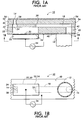
- FIGS. 1A and 1B shows a prior art single ink jet 10 that is suitable for use in a high-resolution ink jet array print head.
- the ink jet 10 has a body that defines an ink manifold 12 through which ink is delivered to the ink jet print head.
- the body also defines an ink drop-forming orifice 14 together with an ink flow path from ink manifold 12 to orifice 14.
- the ink jet print head preferably includes an array of orifices 14 that are closely spaced apart from one another for use in ejecting drops of ink onto an image-receiving medium (not shown), such as a sheet of paper or a transfer drum.
- a typical ink jet print head has at least four manifolds for receiving black (“K”), cyan (“C”), magenta (“M”), and yellow (“Y”) ink for use in black plus subtractive three-color printing.
- Ink flows from manifold 12 through an inlet port 16, an inlet channel 18, a pressure chamber port 20 and into an ink pressure chamber 22.
- Ink leaves pressure chamber 22 by way of an outlet port 24 and flows through an outlet channel 28 to nozzle 14, from which ink drops are ejected.
- an offset channel may be added between pressure chamber 22 and orifice 14 to suit particular ink jet applications.
- Ink pressure chamber 22 is bounded on one side by a flexible diaphragm 30.
- a piezoelectric transducer 32 is secured to diaphragm 30 by an appropriate adhesive and overlays ink pressure chamber 22.
- piezoelectric transducer 32 has metal film layers 34 to which an electronic transducer driver 36 is electrically connected. Although other forms of transducers may be used, piezoelectric transducer 32 is operated in its bending mode such that when a voltage is applied across metal film layers 34, transducer 32 attempts to change its dimensions.
- piezoelectric transducer 32 bends, deforming diaphragm 30, thereby displacing ink in ink pressure chamber 22, causing the outward flow of ink through outlet port 24 and outlet channel 28 to orifice 14. Refill of ink pressure chamber 22 following the ejection of an ink drop is augmented by the orifice meniscus, reverse bending of piezoelectric transducer 32 and the concomitant movement of diaphragm 30.
- ink jet 10 is preferably formed of multiple laminated plates or sheets, such as of stainless steel. These sheets are stacked in a superimposed relationship. Referring once again to FIGS. 1A and 1B, these sheets or plates include a diaphragm plate 40, which forms diaphragm 30 and a portion of manifold 12; an ink pressure chamber plate 42, which defines ink pressure chamber 22 and a portion of manifold 12; an inlet channel plate 46, which defines inlet channel 18 and outlet port 24; an outlet plate 54, which defines outlet channel 28; and an orifice plate 56, which defines orifice 14 of ink jet 10.
- diaphragm plate 40 which forms diaphragm 30 and a portion of manifold 12
- an ink pressure chamber plate 42 which defines ink pressure chamber 22 and a portion of manifold 12
- an inlet channel plate 46 which defines inlet channel 18 and outlet port 24
- an outlet plate 54 which defines outlet channel 28
- an orifice plate 56 which defines orifice 14 of ink jet 10.
- the piezoelectric transducer 32 is bonded to a thin plate (diaphragm 30) above a fluid filled chamber or ink pressure chamber 22. As described above, when voltage is applied to the piezoelectric transducer 22, it tries to change shape. Since one edge is constrained by the diaphragm 30, bending occurs instead. In prior art applications, the piezoelectric transducer 32 is intended to be the same size and shape as the ink pressure chamber 22.
- FIGS. 2A and 2B there is shown a single ink jet 10 with the piezoelectric transducer 32 in accordance with one preferred embodiment of the present invention for use in a high-resolution ink jet array print head.
- diaphragm plate 40 overlays the chamber aperture 42 of ink pressure chamber 22 forming the overlaying diaphragm 30.
- the piezoelectric transducer 32 having metal film layers 34 on a top side 44 and underside 46 is bonded to diaphragm 30 on the underside 46 above the ink pressure chamber 22.
- the outer perimeter 48 of piezoelectric transducer 32 overlaps the chamber aperture 42 of ink pressure chamber 22 to improve process capability and reduce voltage sensitivity, as is more fully described below.
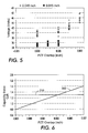
- FIG. 6 by centering the piezoelectric transducer width in the flat spot, alignment specifications may be opened up or process capabilities for a given specification range increase.
- Cpks ⁇ 1.3 With smaller nominal piezoelectric transducer widths, preliminary calculations and empirical data indicated that narrow width piezoelectric transducers would cause unacceptable manufacturing process 210 (i.e., Cpks ⁇ 1.3). Larger piezoelectric transducers allow larger tolerances on misalignment for this process.
- FIG. 6 demonstrates a Cpk > 1.4 200 for this alignment process with the larger piezoelectric transducer.
- the present invention addresses efficiency variation introduced by piezoelectric transducer misregistration and other process-related yield issues without significant loss in jetting efficiency.
- process improvements are made without significant loss to jetting efficiency.
- bonding layer alignment capability in addition to reducing the overall voltage variation inherent in the design is accomplished.
Landscapes
- Engineering & Computer Science (AREA)
- Manufacturing & Machinery (AREA)
- Particle Formation And Scattering Control In Inkjet Printers (AREA)
Abstract
A piezoelectric transducer for use in an ink jet print head is
disclosed. The ink jet print head defines an ink pressure chamber that further
defines a chamber aperture having an overlaying flexible diaphragm. The
piezoelectric transducer has a top side, an under side secured to the flexible
diaphragm and an outer perimeter sized and positioned to overlap the chamber
aperture wherein the overlap improves process capability and reduces voltage
sensitivity.
Description
- There are well-known apparatuses and methods for implementing multiple-orifice drop-on-demand ink jet print heads. In general, each ink jet of a multiple-orifice drop-on-demand ink jet array print head operates by the displacement of ink in an ink pressure chamber and the subsequent ejection of ink droplets from an associated orifice. Ink is supplied from a common ink supply manifold through an ink inlet to the ink pressure chamber. A jet driver mechanism is used to displace the ink in the ink pressure chamber. The jet driver mechanism typically includes a piezoelectric transducer bonded to a thin diaphragm overlaying a chamber aperture defined by the ink pressure chamber. When a voltage is applied to the piezoelectric transducer, it displaces ink in the ink pressure chamber, causing the ink to flow through the inlet from the ink manifold to the ink pressure chamber and through an outlet and passageway to the orifice.
- Individual jet driver mechanism design plays a major role in determining jet efficiency and maximum operating frequency. Jet efficiency is affected by the size of the piezoelectric transducer in relationship to the ink pressure chamber. Choosing a piezoelectric transducer size smaller than the ink pressure chamber may optimize nominal driver efficiency, but manufacturing robustness may be compromised. Additionally, high voltage sensitivity results in variations in the alignment and size of the piezoelectric transducer to the ink pressure chamber. High voltage sensitivity requires tight tolerances on manufacturing variations.
- What is needed, therefore, is a piezoelectric transducer that when used in a jet driver mechanism design reduces voltage sensitivity while improving manufacturability. To achieve the foregoing, a piezoelectric transducer for use in an ink jet print head is disclosed having an outer perimeter sized and positioned to overlap the chamber aperture of the ink pressure chamber such that the overlap improves process capability and reduces voltage sensitivity. Therefore, manufacturability may be improved without significant impact to driver efficiency simply by increasing the piezoelectric transducer size to overlap the edge of the ink pressure chamber.
- In one embodiment the piezoelectric transducer as defined in
claim 1 further comprises said outer perimeter defining a radius and the chamber aperture defining a radius wherein said outer perimeter overlaps the chamber aperture approximately five percent or less.
In a further embodiment the piezoelectric transducer further comprises said outer perimeter overlaps the chamber aperture having a width of approximately 40 mil by approximately 5 mils or less. - The disclosed piezoelectric transducer is capable of other different embodiments and its details are capable of modifications in various, obvious aspects all without departing from the invention. Accordingly, the drawings and descriptions will be regarded as illustrative in nature and not as restrictive. And now for a brief description of the drawings.
-
- FIG. 1A is an enlarged prior art diagrammatical cross-sectional view of an piezoelectric transducer driven ink jet showing a plate-stacking arrangement of internal features thereof suitable for use in an ink jet array print head;
- FIG. 1B is a top plan view of FIG. 1A;
- FIG. 2A is an enlarged diagrammatical cross-sectional view of an piezoelectric transducer driven ink jet showing a plate-stacking arrangement of internal features for use in the present invention;
- FIG. 2B is an enlarged top plan view of the piezoelectric transducer of FIG. 1A for use in accordance with the present invention;
- FIG. 3 is a graphical representation of maximum deflection obtained as piezoelectric width is varied relative to chamber aperture width;
- FIG. 4 is a graphical representation of normalized displacement versus piezoelectric overlap;
- FIG. 5 is a graphical representation of voltage versus piezoelectric overlap relative to chamber aperture width; and
- FIG. 6 is a graphical representation of capability index versus piezoelectric overlap.
-
- FIGS. 1A and 1B shows a prior art
single ink jet 10 that is suitable for use in a high-resolution ink jet array print head. Theink jet 10 has a body that defines anink manifold 12 through which ink is delivered to the ink jet print head. The body also defines an ink drop-formingorifice 14 together with an ink flow path fromink manifold 12 to orifice 14. In general, the ink jet print head preferably includes an array oforifices 14 that are closely spaced apart from one another for use in ejecting drops of ink onto an image-receiving medium (not shown), such as a sheet of paper or a transfer drum. A typical ink jet print head has at least four manifolds for receiving black ("K"), cyan ("C"), magenta ("M"), and yellow ("Y") ink for use in black plus subtractive three-color printing. Ink flows from manifold 12 through aninlet port 16, aninlet channel 18, apressure chamber port 20 and into anink pressure chamber 22. Inkleaves pressure chamber 22 by way of anoutlet port 24 and flows through anoutlet channel 28 tonozzle 14, from which ink drops are ejected. Alternatively, an offset channel may be added betweenpressure chamber 22 andorifice 14 to suit particular ink jet applications. -
Ink pressure chamber 22 is bounded on one side by aflexible diaphragm 30. Apiezoelectric transducer 32 is secured todiaphragm 30 by an appropriate adhesive and overlaysink pressure chamber 22. In a conventional manner,piezoelectric transducer 32 hasmetal film layers 34 to which anelectronic transducer driver 36 is electrically connected. Although other forms of transducers may be used,piezoelectric transducer 32 is operated in its bending mode such that when a voltage is applied acrossmetal film layers 34, transducer 32 attempts to change its dimensions. However, because it is securely and rigidly bonded to thediaphragm 30,piezoelectric transducer 32 bends, deformingdiaphragm 30, thereby displacing ink inink pressure chamber 22, causing the outward flow of ink throughoutlet port 24 andoutlet channel 28 to orifice 14. Refill ofink pressure chamber 22 following the ejection of an ink drop is augmented by the orifice meniscus, reverse bending ofpiezoelectric transducer 32 and the concomitant movement ofdiaphragm 30. - To facilitate manufacture of an ink jet array print head,
ink jet 10 is preferably formed of multiple laminated plates or sheets, such as of stainless steel. These sheets are stacked in a superimposed relationship. Referring once again to FIGS. 1A and 1B, these sheets or plates include adiaphragm plate 40, which formsdiaphragm 30 and a portion ofmanifold 12; an inkpressure chamber plate 42, which definesink pressure chamber 22 and a portion ofmanifold 12; aninlet channel plate 46, which definesinlet channel 18 andoutlet port 24; anoutlet plate 54, which definesoutlet channel 28; and anorifice plate 56, which definesorifice 14 ofink jet 10. Thepiezoelectric transducer 32 is bonded to a thin plate (diaphragm 30) above a fluid filled chamber orink pressure chamber 22. As described above, when voltage is applied to thepiezoelectric transducer 22, it tries to change shape. Since one edge is constrained by thediaphragm 30, bending occurs instead. In prior art applications, thepiezoelectric transducer 32 is intended to be the same size and shape as theink pressure chamber 22. - Referring now to FIGS. 2A and 2B, there is shown a
single ink jet 10 with thepiezoelectric transducer 32 in accordance with one preferred embodiment of the present invention for use in a high-resolution ink jet array print head. As in the priorart diaphragm plate 40 overlays thechamber aperture 42 ofink pressure chamber 22 forming theoverlaying diaphragm 30. Thepiezoelectric transducer 32 havingmetal film layers 34 on atop side 44 andunderside 46 is bonded todiaphragm 30 on theunderside 46 above theink pressure chamber 22. In accordance with the present invention, theouter perimeter 48 ofpiezoelectric transducer 32 overlaps thechamber aperture 42 ofink pressure chamber 22 to improve process capability and reduce voltage sensitivity, as is more fully described below. - As stated before, individual jet driver mechanism design plays a major role in determining jet efficiency and maximum operating frequency. More specifically, jet driver mechanism design is a trade off between the maximum deflection of the
diaphragm 30 obtained for a given voltage and the maximum natural frequency that can be obtained with theelectronic transducer driver 36. That is, there is a trade off between driver efficiency and the maximum jetting frequency of the individual jet. Jetting efficiency is defined as: - Turning now to the graphical representations of FIGS. 3 and 4, deflection of the driver and natural frequency can be predicted using simple pressure generation models known in the art. In many cases, a rectangular geometry may be reduced using simple plate bending theory to a circular geometry suitable for evaluation in this simpler model. Using these tools, analytical work directed toward finding the important effects of piezoelectric transducer width on jetting parameters was performed. Referring to FIG. 2, the
results 100 of this analysis shows that the primary effect ofpiezoelectric transducer overlap 104 would be to change thevolumetric displacement 102 generated by the electronic transducer driver at a fixed applied voltage. The optimum displacement is obtained with a piezoelectric transducer sized at approximately 95% of the chamber aperture width. - Referring to FIG. 4, conversely, the amount of voltage needed to produce a desired displacement (or drop size) would be changed by the piezoelectric transducer overlap as shown in 140, 142 and 145 for a fixed voltage. The analysis predicted that the critical parameter with respect to piezoelectric transducer/body configuration is piezoelectric transducer overlap, and not the actual piezoelectric transducer or body sizes themselves. Within a small underlap region, almost no change in displacement at fixed voltage should be expected (or voltage at fixed displacement). Beyond this region, a decrease in displacement is seen as overlap increases. The rate at which displacement decreases increases exponentially as piezoelectric transducer overlap increases.
- Referring to FIG. 5, experimental results graphically reveal a flat spot in efficiency for an oversized piezoelectric transducer. Regardless of nominal body width, driver efficiency remains relatively unchanged over the range of piezoelectric transducer overlap from 0 to 5 mils for a chamber aperture width of 40 to 45 mils. Beyond this, efficiency begins to rapidly decrease. Therefore, referring once again to FIG. 2B, for a given
aperture width 50 orlength 52, theoverlap 31 of the outer perimeter edges 54 ofpiezoelectric transducer 32 is approximately five percent or less or a total often percent or less from the center of the piezoelectric transducer's center of either thechambers aperture width 50 orlength 52 or both. Additionally, although not shown, it should be understood that the chamber aperture and piezoelectric transducers outer perimeter may have a circular configuration wherein the overlap is five percent or less the radius of the outer perimeter to the radius of the chamber aperture. - Lastly, referring to FIG. 6, by centering the piezoelectric transducer width in the flat spot, alignment specifications may be opened up or process capabilities for a given specification range increase. With smaller nominal piezoelectric transducer widths, preliminary calculations and empirical data indicated that narrow width piezoelectric transducers would cause unacceptable manufacturing process 210 (i.e., Cpks < 1.3). Larger piezoelectric transducers allow larger tolerances on misalignment for this process. FIG. 6 demonstrates a Cpk > 1.4 200 for this alignment process with the larger piezoelectric transducer.
- In summary, the present invention addresses efficiency variation introduced by piezoelectric transducer misregistration and other process-related yield issues without significant loss in jetting efficiency. By over sizing the piezoelectric transducer relative to chamber aperture width, length or both, process improvements are made without significant loss to jetting efficiency. Additionally, bonding layer alignment capability in addition to reducing the overall voltage variation inherent in the design is accomplished.
Claims (10)
- A piezoelectric transducer for use in an ink jet print head defining an ink pressure chamber aperture, comprising:a piezoelectric transducer defining an outer perimeter, said outer perimeter sized and positioned to overlap the chamber aperture.
- The piezoelectric transducer according to Claim 1 further comprising:said outer perimeter defining first and second opposing outer perimeter edges wherein any two opposing outer perimeter edges overlaps the chamber aperture.
- The piezoelectric transducer according to Claim 1 further comprising:said outer perimeter overlaps the chamber aperture having a width a total of approximately ten percent or less the chamber aperture's width.
- The piezoelectric transducer according to Claim 1 further comprising:said outer perimeter overlaps the chamber aperture having a length a total of approximately ten percent or less the chamber aperture's length.
- The piezoelectric transducer according to Claim 3 further comprising:said first opposing outer perimeter edges overlaps the chamber aperture approximately five percent or less of the chamber aperture width on each said edge.
- The piezoelectric transducer according to claim 4 further comprising:said second opposing outer perimeter edges overlaps the chamber aperture approximately five percent or less of the chamber aperture length on each said edge.
- The piezoelectric transducer according to claim 2 further comprising:said first and second opposing outer perimeter edges overlaps the chamber aperture approximately five percent or less of the chamber aperture on each said edge.
- The piezoelectric transducer according to claim 2 further comprising:said first and second opposing outer perimeter edges overlaps a width and length of the chamber aperture for a total of approximately ten percent or less of the chamber aperture's width and length.
- An ink jet print head, comprising:an ink pressure chamber, said ink pressure chamber defining a chamber aperture;a flexible diaphragm overlaying said chamber aperture;a piezoelectric transducer according to any of the claims 1 to 8.
- An ink jet print head, comprising:an ink pressure chamber, said ink pressure chamber defining a chamber aperture;a flexible diaphragm overlaying said chamber aperture;a piezoelectric transducer having a top side, an under side and an outer perimeter, said underside secured to said flexible diaphragm, said outer perimeter defining first and second opposing outer perimeter edges wherein any two opposing outer perimeter edges are sized and positioned to overlap said chamber aperture wherein said overlap improves process capability and reduces voltage sensitivity.
Applications Claiming Priority (2)
| Application Number | Priority Date | Filing Date | Title |
|---|---|---|---|
| US891742 | 1992-06-01 | ||
| US09/891,742 US20020196314A1 (en) | 2001-06-25 | 2001-06-25 | Piezoelectric transducer |
Publications (1)
| Publication Number | Publication Date |
|---|---|
| EP1270227A1 true EP1270227A1 (en) | 2003-01-02 |
Family
ID=25398743
Family Applications (1)
| Application Number | Title | Priority Date | Filing Date |
|---|---|---|---|
| EP02014181A Withdrawn EP1270227A1 (en) | 2001-06-25 | 2002-06-25 | Piezoelectric transducer |
Country Status (3)
| Country | Link |
|---|---|
| US (1) | US20020196314A1 (en) |
| EP (1) | EP1270227A1 (en) |
| JP (1) | JP2003025573A (en) |
Families Citing this family (8)
| Publication number | Priority date | Publication date | Assignee | Title |
|---|---|---|---|---|
| JP4706913B2 (en) * | 2004-08-27 | 2011-06-22 | 富士フイルム株式会社 | Discharge head and image forming apparatus |
| US7585061B2 (en) * | 2004-08-27 | 2009-09-08 | Fujifilm Corporation | Ejection head and image forming apparatus |
| JP4876554B2 (en) * | 2005-12-02 | 2012-02-15 | リコープリンティングシステムズ株式会社 | Inkjet head manufacturing method |
| US7530675B2 (en) * | 2006-07-20 | 2009-05-12 | Xerox Corporation | Piezoelectric actuator device |
| US7819509B2 (en) * | 2006-09-29 | 2010-10-26 | Fujifilm Corporation | Liquid ejection head and manufacturing method thereof |
| JP5101966B2 (en) * | 2006-09-29 | 2012-12-19 | 富士フイルム株式会社 | Liquid discharge head and manufacturing method thereof |
| US7857432B2 (en) * | 2009-02-24 | 2010-12-28 | Xerox Corporation | Drop generator |
| WO2011053320A1 (en) * | 2009-10-30 | 2011-05-05 | Hewlett-Packard Development Company, L.P. | Piezoelectric actuator having embedded electrodes |
Citations (5)
| Publication number | Priority date | Publication date | Assignee | Title |
|---|---|---|---|---|
| EP0786346A2 (en) * | 1996-01-26 | 1997-07-30 | Seiko Epson Corporation | Ink-jet recording head |
| US6070972A (en) * | 1993-10-19 | 2000-06-06 | Francotyp-Postalia Ag & Co. | Face shooter ink jet printing head |
| US6073321A (en) * | 1994-04-26 | 2000-06-13 | Seiko Epson Corporation | Manufacturing method for an ink jet recording head |
| EP1083048A1 (en) * | 1998-06-02 | 2001-03-14 | NEC Corporation | Ink jet recording head and manufacturing method thereof |
| EP1108543A1 (en) * | 1999-12-01 | 2001-06-20 | Seiko Epson Corporation | Ink-jet recording head |
-
2001
- 2001-06-25 US US09/891,742 patent/US20020196314A1/en not_active Abandoned
-
2002
- 2002-06-24 JP JP2002182356A patent/JP2003025573A/en not_active Withdrawn
- 2002-06-25 EP EP02014181A patent/EP1270227A1/en not_active Withdrawn
Patent Citations (5)
| Publication number | Priority date | Publication date | Assignee | Title |
|---|---|---|---|---|
| US6070972A (en) * | 1993-10-19 | 2000-06-06 | Francotyp-Postalia Ag & Co. | Face shooter ink jet printing head |
| US6073321A (en) * | 1994-04-26 | 2000-06-13 | Seiko Epson Corporation | Manufacturing method for an ink jet recording head |
| EP0786346A2 (en) * | 1996-01-26 | 1997-07-30 | Seiko Epson Corporation | Ink-jet recording head |
| EP1083048A1 (en) * | 1998-06-02 | 2001-03-14 | NEC Corporation | Ink jet recording head and manufacturing method thereof |
| EP1108543A1 (en) * | 1999-12-01 | 2001-06-20 | Seiko Epson Corporation | Ink-jet recording head |
Also Published As
| Publication number | Publication date |
|---|---|
| US20020196314A1 (en) | 2002-12-26 |
| JP2003025573A (en) | 2003-01-29 |
Similar Documents
| Publication | Publication Date | Title |
|---|---|---|
| EP0732208B1 (en) | Ink jet print head having ceramic ink pump member and metallic nozzle member bonded thereto | |
| EP2343187B1 (en) | Droplet deposition apparatus | |
| US6290340B1 (en) | Multi-layer ink jet print head and manufacturing method therefor | |
| US8042919B2 (en) | Piezoelectric inkjet printhead | |
| JP4727382B2 (en) | Piezoelectric inkjet printhead with one-way shutter | |
| US7571990B2 (en) | Inkjet heads | |
| US20020196314A1 (en) | Piezoelectric transducer | |
| US6592216B2 (en) | Ink jet print head acoustic filters | |
| US7645032B2 (en) | Droplet ejection head and method of manufacturing the same | |
| JP4661354B2 (en) | Liquid transfer device | |
| JP4945647B2 (en) | Droplet generator | |
| US7934814B2 (en) | Droplet ejection head and method of manufacturing the same | |
| JP2012061689A (en) | Liquid droplet ejection head, method for manufacturing liquid droplet ejection head, liquid cartridge and image forming apparatus | |
| US7334879B2 (en) | Ink-jet head | |
| JPS60232967A (en) | Ink jet head | |
| JP4013625B2 (en) | Inkjet head | |
| JP7800075B2 (en) | Liquid ejection head | |
| JP2005297557A (en) | Inkjet head | |
| EP1972449B1 (en) | Liquid droplet ejection apparatus | |
| JP2002001945A (en) | Ink jet head and ink jet recording apparatus | |
| KR20070079296A (en) | Piezoelectric inkjet printheads | |
| JP2005022135A (en) | Piezoelectric inkjet head | |
| JP2006347169A (en) | Droplet generator | |
| JP2006123275A (en) | Liquid transfer device and method for manufacturing liquid transfer device | |
| JP2002248758A (en) | Ink jet recording head and ink jet recording apparatus |
Legal Events
| Date | Code | Title | Description |
|---|---|---|---|
| PUAI | Public reference made under article 153(3) epc to a published international application that has entered the european phase |
Free format text: ORIGINAL CODE: 0009012 |
|
| AK | Designated contracting states |
Kind code of ref document: A1 Designated state(s): AT BE CH CY DE DK ES FI FR GB GR IE IT LI LU MC NL PT SE TR |
|
| AX | Request for extension of the european patent |
Free format text: AL;LT;LV;MK;RO;SI |
|
| 17P | Request for examination filed |
Effective date: 20021114 |
|
| AKX | Designation fees paid |
Designated state(s): DE FR GB |
|
| 17Q | First examination report despatched |
Effective date: 20041207 |
|
| STAA | Information on the status of an ep patent application or granted ep patent |
Free format text: STATUS: THE APPLICATION IS DEEMED TO BE WITHDRAWN |
|
| 18D | Application deemed to be withdrawn |
Effective date: 20050103 |