EP1270145A2 - Machine outil avec porte-outil rotative pour plusieurs outils - Google Patents
Machine outil avec porte-outil rotative pour plusieurs outils Download PDFInfo
- Publication number
- EP1270145A2 EP1270145A2 EP02013041A EP02013041A EP1270145A2 EP 1270145 A2 EP1270145 A2 EP 1270145A2 EP 02013041 A EP02013041 A EP 02013041A EP 02013041 A EP02013041 A EP 02013041A EP 1270145 A2 EP1270145 A2 EP 1270145A2
- Authority
- EP
- European Patent Office
- Prior art keywords
- axis
- tool
- tools
- tool carrier
- carrier head
- Prior art date
- Legal status (The legal status is an assumption and is not a legal conclusion. Google has not performed a legal analysis and makes no representation as to the accuracy of the status listed.)
- Withdrawn
Links
Images


Classifications
-
- B—PERFORMING OPERATIONS; TRANSPORTING
- B23—MACHINE TOOLS; METAL-WORKING NOT OTHERWISE PROVIDED FOR
- B23Q—DETAILS, COMPONENTS, OR ACCESSORIES FOR MACHINE TOOLS, e.g. ARRANGEMENTS FOR COPYING OR CONTROLLING; MACHINE TOOLS IN GENERAL CHARACTERISED BY THE CONSTRUCTION OF PARTICULAR DETAILS OR COMPONENTS; COMBINATIONS OR ASSOCIATIONS OF METAL-WORKING MACHINES, NOT DIRECTED TO A PARTICULAR RESULT
- B23Q39/00—Metal-working machines incorporating a plurality of sub-assemblies, each capable of performing a metal-working operation
- B23Q39/02—Metal-working machines incorporating a plurality of sub-assemblies, each capable of performing a metal-working operation the sub-assemblies being capable of being brought to act at a single operating station
- B23Q39/021—Metal-working machines incorporating a plurality of sub-assemblies, each capable of performing a metal-working operation the sub-assemblies being capable of being brought to act at a single operating station with a plurality of toolheads per workholder, whereby the toolhead is a main spindle, a multispindle, a revolver or the like
- B23Q39/022—Metal-working machines incorporating a plurality of sub-assemblies, each capable of performing a metal-working operation the sub-assemblies being capable of being brought to act at a single operating station with a plurality of toolheads per workholder, whereby the toolhead is a main spindle, a multispindle, a revolver or the like with same working direction of toolheads on same workholder
- B23Q39/024—Metal-working machines incorporating a plurality of sub-assemblies, each capable of performing a metal-working operation the sub-assemblies being capable of being brought to act at a single operating station with a plurality of toolheads per workholder, whereby the toolhead is a main spindle, a multispindle, a revolver or the like with same working direction of toolheads on same workholder consecutive working of toolheads
-
- B—PERFORMING OPERATIONS; TRANSPORTING
- B23—MACHINE TOOLS; METAL-WORKING NOT OTHERWISE PROVIDED FOR
- B23Q—DETAILS, COMPONENTS, OR ACCESSORIES FOR MACHINE TOOLS, e.g. ARRANGEMENTS FOR COPYING OR CONTROLLING; MACHINE TOOLS IN GENERAL CHARACTERISED BY THE CONSTRUCTION OF PARTICULAR DETAILS OR COMPONENTS; COMBINATIONS OR ASSOCIATIONS OF METAL-WORKING MACHINES, NOT DIRECTED TO A PARTICULAR RESULT
- B23Q39/00—Metal-working machines incorporating a plurality of sub-assemblies, each capable of performing a metal-working operation
- B23Q39/02—Metal-working machines incorporating a plurality of sub-assemblies, each capable of performing a metal-working operation the sub-assemblies being capable of being brought to act at a single operating station
- B23Q39/021—Metal-working machines incorporating a plurality of sub-assemblies, each capable of performing a metal-working operation the sub-assemblies being capable of being brought to act at a single operating station with a plurality of toolheads per workholder, whereby the toolhead is a main spindle, a multispindle, a revolver or the like
- B23Q39/025—Metal-working machines incorporating a plurality of sub-assemblies, each capable of performing a metal-working operation the sub-assemblies being capable of being brought to act at a single operating station with a plurality of toolheads per workholder, whereby the toolhead is a main spindle, a multispindle, a revolver or the like with different working directions of toolheads on same workholder
- B23Q39/026—Metal-working machines incorporating a plurality of sub-assemblies, each capable of performing a metal-working operation the sub-assemblies being capable of being brought to act at a single operating station with a plurality of toolheads per workholder, whereby the toolhead is a main spindle, a multispindle, a revolver or the like with different working directions of toolheads on same workholder simultaneous working of toolheads
-
- B—PERFORMING OPERATIONS; TRANSPORTING
- B23—MACHINE TOOLS; METAL-WORKING NOT OTHERWISE PROVIDED FOR
- B23Q—DETAILS, COMPONENTS, OR ACCESSORIES FOR MACHINE TOOLS, e.g. ARRANGEMENTS FOR COPYING OR CONTROLLING; MACHINE TOOLS IN GENERAL CHARACTERISED BY THE CONSTRUCTION OF PARTICULAR DETAILS OR COMPONENTS; COMBINATIONS OR ASSOCIATIONS OF METAL-WORKING MACHINES, NOT DIRECTED TO A PARTICULAR RESULT
- B23Q39/00—Metal-working machines incorporating a plurality of sub-assemblies, each capable of performing a metal-working operation
- B23Q39/04—Metal-working machines incorporating a plurality of sub-assemblies, each capable of performing a metal-working operation the sub-assemblies being arranged to operate simultaneously at different stations, e.g. with an annular work-table moved in steps
- B23Q39/048—Metal-working machines incorporating a plurality of sub-assemblies, each capable of performing a metal-working operation the sub-assemblies being arranged to operate simultaneously at different stations, e.g. with an annular work-table moved in steps the work holder of a work station transfers directly its workpiece to the work holder of a following work station
-
- B—PERFORMING OPERATIONS; TRANSPORTING
- B23—MACHINE TOOLS; METAL-WORKING NOT OTHERWISE PROVIDED FOR
- B23Q—DETAILS, COMPONENTS, OR ACCESSORIES FOR MACHINE TOOLS, e.g. ARRANGEMENTS FOR COPYING OR CONTROLLING; MACHINE TOOLS IN GENERAL CHARACTERISED BY THE CONSTRUCTION OF PARTICULAR DETAILS OR COMPONENTS; COMBINATIONS OR ASSOCIATIONS OF METAL-WORKING MACHINES, NOT DIRECTED TO A PARTICULAR RESULT
- B23Q39/00—Metal-working machines incorporating a plurality of sub-assemblies, each capable of performing a metal-working operation
- B23Q2039/004—Machines with tool turrets
Definitions
- the invention relates to a machine tool comprising a machine frame, one held on the machine frame and rotatable about a spindle axis Work spindle for holding a workpiece, a first tool holder with a tool carrier head rotatable about an axis relative to a bearing housing, the work spindle and the tool carrier head being relative to each other by means of a control at least in the direction of one transverse to Spindle axis running transverse movement axis and one parallel to the spindle axis extending longitudinal movement axis are controlled and the Working spindle can be rotated around the spindle axis as a controlled C axis is positionable.
- the solution according to the invention consists of suitable ones Rotation of the tool holder head allows the tools to be attached to one Use the circumferential side or an end face of the workpiece.
- the tool carrier head on at least two different Side tool holders for tools carries.
- the tool carrier head on at least four different Side tool holders for tools carries.
- the different sides of the tool carrier head are preferred formed by side surfaces of the tool carrier head, the Side surfaces are arranged so that their surface normals into different Show directions.
- the side surfaces can be curved. However, it is particularly favorable if the side surfaces are flat surfaces.
- Tool carrier head With regard to the design of the tool carrier head, the most varied geometric shapes conceivable. For example, it would be conceivable that Tool carrier head spherical or ellipsoidal or also conical train, these body shapes also with additional flats can be provided.
- the tool carrier head as a prismatic body is formed and the axis of the prismatic body parallel to one Side surface interspersed.
- the axis preferably runs here parallel to the central axis of the prismatic body.
- the prismatic body is in Direction of the axis has an extent which is at least as large as in any direction across the axis.
- the prismatic body is one in the direction of the axis Expansion that is at least 1.5 times the maximum expansion across the axis.
- the base of the prismatic body can be the most varied Have shapes.
- the base can also be round or have an elliptical shape.
- a particularly favorable solution provides that the prismatic body as Base area has a polygon.
- the polygon is preferably a maximum of one hexagon, more advantageously are base areas in the form of a pentagon or a quadrangle, on the one hand to be able to provide as many tool holders as possible and on the other hand the To be able to use tools with the lowest possible risk of collision.
- the tool carrier head With regard to the expansion of the tool carrier head, none have so far details given. So that the tool carrier head, however its size does not adversely affect the size of the machine tool preferably provided that the tool carrier head transverse to the axis maximum extent, which is at most 8 times a maximum Corresponds to the workpiece diameter.
- the tool carrier head has a maximum transverse to the axis Expansion that is at most 6 times a maximum Corresponds to the workpiece diameter.
- the tool carrier head has side faces, it is preferred provided that the side surfaces are spaced from the axis which is a maximum of 4 times the maximum workpiece diameter equivalent.
- the tool carrier head at least around the axis Can be rotated 360 °, so that optimum flexibility in assembly the tool carrier head with tools and when using these tools given is.
- a preferred solution provides that the tool carrier head can be rotated about the axis in discrete rotational positions is.
- the rotational positions by the main directions on the Tool carrier head provided tools are specified and the Main directions of the tools correspond, so that each tool with can bring its main direction into working position.
- the discrete rotational positions it is particularly favorable if the discrete rotary positions arranged at the same angular distance from each other are so that fixing devices for fixing the tool carrier head can be provided with a corresponding multiple symmetry.
- the tool carrier head has more discrete rotational positions has as main directions in which the tool holders tools that can be used on the tool carrier head can extend.
- the individual tools can also be aligned to be used in which the main directions are not parallel to the X axis or extend parallel to the Z axis, but also at least at an angle this.
- a particularly favorable solution provides that angular distances between the discrete rotational positions of the tool carrier head are less than 10 °.
- the angular distances are an integral multiple of 1.25 °, that is 1.25 ° or 2.5 ° or 5 °.
- the tool carrier head is rotatable about the axis as controlled by the control B axis and thus the control has the option of turning the tool carrier head into any Rotate rotary positions to analogous to the known in these rotary positions B axis to be able to machine the workpiece.
- the tool carrier head With regard to the storage of the tool carrier head, none have so far details given. It would be conceivable, for example, the tool carrier head to be rotatably supported on the bearing housing.
- the tool carrier head can be stored particularly cheaply if this is rotatably supported between the arms of a holding fork about the axis, so that a sufficiently stable and space-saving for a machine tool Construction is possible.
- the tool carrier head with mounted tools can be rotated without collision with respect to the holding fork.
- the tool holders for the tools can be any be distributed on the tool carrier head.
- One especially for control and Also the freedom from collisions when using the tool carrier head is favorable Solution provides that the tool carrier head for at least two receptacles Carries tools that are common to themselves with their main directions tool plane perpendicular to the axis. With so arranged Tool holders can be particularly cheap Arrange several tools and avoid collisions.
- the tool change direction runs parallel to the axis about which the tool carrier head is rotatable.
- the Tool holder head has such arranged tool holders that in these used tools point in the main directions that in the respective Tool plane in the direction in which they have a cutting effect, an angular distance with respect to the axis of at least 60 ° from each other, so that through this angular distance there is sufficient space for in the azimuthal direction adjacent tool.
- such a structure also has the Advantage that the tool carrier head is as small and compact as possible can be formed and thus the tool tips as a whole are close to the axis, so that those occurring during machining Torques around the axis due to the smallest possible lever arm for the fixing device provided for the tool carrier head is easily accommodated can be.
- the tools are arranged in this way on the tool carrier head are that the main directions in the respective tool plane in the Direction in which the tools are cutting, an angular distance of have at least 90 ° from each other.
- the tool carrier head has a plurality of tool holder receptacles which are arranged in such a way that main directions of tools used in these are in one lie parallel to the alignment plane.
- the alignment level can run in a wide variety of ways.
- Another solution provides that the alignment plane is opposite the axis laterally offset.
- the tool carrier head Has tool holders, which are arranged so that main directions of tools used in these in two parallel to the axis and transversely mutually aligned alignment planes.
- a particularly expedient solution proposes that a first alignment plane running parallel to the axis this runs through and at least a second one running parallel to the axis Alignment plane is transverse to this and at a distance from the axis.
- the second alignment plane can be at any angle first alignment level. It is particularly favorable if the second Alignment level is perpendicular to the first alignment level.
- Tool holders are holders for stationary tools.
- the tool carrier head with at least one tool holder for a rotating driven Tool is provided.
- This tool holder can be aligned in many different ways his. It is particularly favorable if an axis of rotation of the tool holder for the rotating driven tool in the working position parallel to that of the transverse movement axis and the longitudinal movement axis spanned plane.
- At least one of the rotating drivable tool holder as Tool holder is designed for a heavy-duty tool.
- a heavy-duty tool can be, for example, a gear milling tool, Polygonal milling or a rough milling cutter.
- a tool holder for a rotating driven can be particularly favorable Realize the tool when the tool carrier head has a this tool spindle passing through transversely to the axis with at least has a tool holder.
- Such a spindle which is mounted in the tool carrier head, is in particular suitable for heavy duty tools, for example heavy milling tools that This is an advantage for complete machining that can be carried out as quickly as possible are.
- the tool spindle on both opposite ends each have a tool holder.
- the tool holders for the several rotating driven tools could in principle be driven by their own drives.
- the drive can be designed so that it all Tool holders constantly drives, but only the tool one of the rotating driven tool holders is in use and the other tools run freely. But it is also conceivable to take tool holders can be switched on and off, in which case a detachable one Coupling of the individual tool holders is required.
- Another advantageous solution provides that the individual tool holders are driven at different speeds. For example, a lower speed is selected for heavy-duty tools than for usual rotatingly driven tools, such as usual Drilling and milling. At these different speeds with one To be able to realize common drive, it is preferably provided that through the common drive with at least one of the tool holders greater reduction can be driven than at least one of the other tool holders.
- the drive motor can be started arrange the holding fork for the tool carrier head, so that a directly into the Tool carrier head-guided drive train can be implemented coaxially to the axis is.
- a particularly favorable solution provides that the tool carrier head is movable relative to the work spindle such that in a working position of one of the tools with a transverse to the longitudinal movement axis Main direction the workpiece can be machined circumferentially and that in a working position of one of the tools with transverse to the transverse movement axis machining the workpiece in the main direction can be.
- the first one having the tool carrier head Arrange the tool holder particularly cheaply when the bearing housing is in all possible positions of the tool carrier head relative to the work spindle always on the same side through the spindle axis and across to the spanned by the transverse movement axis and the longitudinal movement axis Plane running center plane is arranged. So that the Make the guidance of the first tool carrier particularly inexpensive.
- the bearing housing of the first tool carrier and a bearing housing of a second tool carrier on opposite one another Sides one through the spindle axis and parallel to the one through the Transverse axis of movement and the longitudinal axis spanned extending Middle plane are arranged.
- the machine frame is one Machine bed body comprises, on one side of which the work spindle is arranged and on the further side of which a sled system is arranged, which is the first tool carrier with the tool carrier head rotatable about the axis wearing.
- a particularly useful solution if a second tool carrier is provided provides that a carriage system which the second tool carrier bears on one side of the Machine bed body is arranged.
- the machine bed body is preferably an elongated prismatic one Body, on the different long sides of which the work spindle and the carriage system are arranged.
- a work spindle Spindle housing can be moved stationary or only in the direction of the longitudinal movement axis arranged on the machine frame, in particular on the machine bed body is.
- Such controlled mobility in the direction of the further transverse movement axis advantageously allows the possibility of different tools Tool levels by moving the tool carrier head in this direction in use on the workpiece.
- the travel paths in the direction of the transverse movement axis and the direction of the longitudinal movement axis are so large that the tool carrier head for processing of the workpiece on a side of the workpiece facing away from the work spindle can be positioned and is therefore easy and inexpensive face machining of the workpiece is possible.
- Machining on an inventive device can be particularly advantageous Carry out the machine tool when the work spindle is opposite a counter spindle is arranged so that machining of the workpiece on a first side in the work spindle and on a second side can take place in the counter spindle.
- the tool carrier head is preferably in the direction of the transverse movement axis and the longitudinal movement axis can be moved such that it can be processed at least one of the workpieces between the work spindle and the counter spindle can be positioned.
- An embodiment of the solution according to the invention is even more advantageous which both the work spindle and the counter spindle according to the invention arranged and trained tool carrier head is assigned.
- FIG. 1 Another embodiment of a lathe according to the invention is seen as a tool carrier head, a first work area and a first one Work spindle assigned to the first tool carrier on the front.
- first tool carrier on the front and the second work spindle in the direction of the spindle axes independently of one another are movable so that when editing the first and second workpiece, the tools of the first tool carrier on the front and the tools of the second front tool carrier independently can be used from each other.
- the movability of the first tool carrier on the front can be designed Realize particularly favorably in the Z direction in that this on a Z-carriage that can be moved in the Z-direction, which in turn sits on the Cross slide for the first tool holder on the front sits.
- the first tool carrier on the front a series of consecutively arranged in a longitudinal direction Has tools.
- the longitudinal direction of such a row can run differently.
- the longitudinal direction runs approximately parallel to the transverse direction, so that by moving the first front tool carrier in the transverse direction at the same time different Tools of the same can be used.
- the number of tools can be multiplied by that the first front tool carrier at least two about a pivot axis has tools arranged at an angular distance from one another, which by pivoting the tool carrier around the pivot axis in a active or inactive position can be brought.
- the pivot axis as by the Machine control controllable B-axis is formed so that the swivel axis not only can the multiple tools be used in Bring active or inactive positions, but also to the tools in inclined with respect to the first spindle axis, for example in one to bring acute angles.
- the invention Machine tool as a tool carrier head in a second work area and a second tool spindle assigned to a second work spindle intended.
- the longitudinal direction can preferably also run differently. As However, it has proven particularly favorable if the longitudinal direction is approximately parallel to the direction of movement of the second front tool carrier runs.
- the second front tool carrier at least two angularly spaced about a pivot axis
- Has tools by pivoting the second tool carrier around the swivel axis from an active to an inactive position and vice versa are movable.
- the pivot axis runs parallel to the rows, so that by swiveling around the Swivel axis different rows of tools of the second front Tool carrier can be used.
- pivot axis is approximately parallel to the direction of movement of the second front tool carrier, so that by swiveling the tools around the swivel axis, no displacement in the direction of the direction of movement.
- the Swivel axis for the second front tool carrier than through the Machine control controllable B-axis is formed, so that also a complete B-axis functionality when swiveling the tools of the second tool holder on the front, and thus this Tools, for example, at defined acute angles relative to the second Spindle axis can be aligned.
- the tools are relative to the pivot axis are arranged so that those acting on the tools during machining Force is directed essentially in the radial direction to the pivot axis, so that the force occurring during machining is negligible or generates at least low torque in the direction of the pivot axis and so the swivel drive for the front tool carrier is not a big one Must withstand moments, which means simple mechanical construction a sufficiently high rigidity can be achieved.
- a lathe comprising a machine frame, a first held on the machine frame and about a first spindle axis rotatable work spindle with a first holder for a first workpiece, at least one first tool carrier, which is used to machine the first Workpiece can be moved in an X direction transversely to the first spindle axis, a second work spindle rotatable about a second spindle axis, which has a second workpiece holder for a second workpiece and which is opposite the first work spindle in a direction transverse to the X direction and transversely to the first spindle axis transverse direction of one with the second spindle axis to the first spindle axis coaxial position in a not Coaxial position can be brought in which the first and the second spindle axis are arranged at a distance from each other, and a first work space assigned first tool holder on the front for machining the first Workpiece
- the first front tool carrier and the second work spindle can be moved together in the transverse direction, so it is required to machine the first workpiece with those in the first front Tool carrier arranged tools and the machining of the second workpiece with the arranged on the second front tool carrier To coordinate tools exactly.
- first front tool carrier and the second work spindle in the transverse direction controlled relative to each other by the machine control are so that the movements of the second work spindle and the first front Tool carrier can be implemented independently of each other.
- a front tool holder is within the scope of this application to understand a tool carrier attached to a front of a work area, in particular opposite the work spindle.
- This front tool carrier can carry tools with which one Front of the workpiece is editable, but also tools for the peripheral Machining at least near the front of the workpiece.
- the relative mobility of the second work spindle and the first on the front Tool carriers can be realized in many different ways become. For example, it would be conceivable to have both on the same Sledge move in the transverse direction and on this common Cross slide an additional cross slide for movement either the second work spindle or the first tool holder on the front to be provided in the transverse direction.
- the first tool carrier on the front could be directly opposite the machine frame with the cross slide to be movable and independent including the second work spindle with the cross slide on the machine frame be movably arranged.
- first cross slide front tool carrier and the cross slide of the second work spindle provide common guides on which both in the transverse direction are led.
- first tool carrier on the front and the second work spindle on a common, opposite in the X direction sit on the machine frame movable carriage.
- Such one Carriage can be formed, for example, by the console.
- This sled offers the possibility, on the one hand, of the tools of the first front tool carrier not only to move in the transverse direction, but also in the X direction, on the other hand this solution opens up a simple possibility the second work spindle coaxial with the first work spindle for transfer position the first machined workpiece in the second work spindle.
- the second front tool carrier with one in the Transverse row of tools provided, so can by Moving in the transverse direction also approached different tools and by the relative position of the second spindle axis the respective tool in the transverse direction also machining in different ways radial distance from the second spindle axis become.
- the second front tool carrier is preferably approximately in the X direction movable.
- the second front Tool carrier on the cross slide for the second work spindle supporting console is movably guided so that the movement of the second Tool carrier relative to the cross slide of the second work spindle load-bearing part and thus no additional position inaccuracies affect the precision when machining the second workpiece.
- the second work spindle is preferably arranged on a Z-slide, which in turn sits on the cross slide.
- this pivot axis could cross in different directions to the second spindle axis.
- a particularly favorable design the solution provides that the pivot axis runs transversely to the X direction.
- pivot axis is approximately parallel to the transverse direction runs so that no by pivoting the second work spindle The same is offset in the transverse direction.
- the first tool carrier on the front is movable in the direction parallel to the first spindle axis.
- the first workpiece it is therefore only necessary for the first workpiece to be movable in the Z direction by means of the first work spindle for the relative positioning of the Tools of the first tool carrier relative to the first workpiece in the Z direction and regardless of the tools of the first front Use tool holder for machining on the first workpiece, with the Z-axis positioning of the first tool holder on the front then the Z-axis positions of the first workpiece, due to the displacement of the first work spindle must be taken into account.
- this gives you the option of using the tools on the front Tool carrier independent of the tools of the first tool carrier to edit.
- the lathe according to the invention can be used when processing the first Workpiece be designed in a variety of ways.
- the lathe as a so-called short lathe train and the first workpiece exclusively through the to lead the first work spindle.
- the first work spindle in the direction the first spindle axis is movably guided on the machine frame, that is is movable in the Z direction, so that a complete machining of the workpiece due to a movability of the first tool carrier in the X direction is possible.
- first tool carrier in the Y direction designed to be movable transversely to the first spindle axis.
- Solution is preferably provided that the guidance of the first workpiece during machining is carried out by a long turning guide bush. So that is done machining the first workpiece in the manner of long turning, the If possible, guide across the spindle axis through the swivel guide bush is done close to the working tools.
- Swiss turning can be done in many different ways be, always a relative movement between the long turning guide bush and the work spindle is required.
- a particularly favorable solution provides that the long turning guide bush in the direction of the first spindle axis on the machine frame is held while expediently the displaceability in the Z direction by moving the first work spindle relative to the long turning guide bush he follows.
- the transverse movement axis is preferably oriented such that it is an X axis corresponds to the machine tool, with the X axis according to usual Definitions in the machine tool industry, especially the lathe industry is aligned.
- the longitudinal axis of movement is aligned according to a Z axis of the machine tool.
- An embodiment of a lathe according to the invention comprises a machine frame 10 with a machine bed body 12, which is designed for example as an elongated body and in particular a base side 14, a spindle carrier side opposite this 16 and between the spindle carrier side 16 and the base side 14 extending carriage support sides 18 and 20, wherein the base side 14, the spindle carrier side 16 and the slide carrier sides 18 and 20 extend parallel to a longitudinal direction 22 of the machine bed body 12.
- a spindle housing sits on the spindle carrier side 16 of the machine bed body 12 24, in which a work spindle designated as a whole by 26 a spindle axis 28 is rotatably supported and drivable.
- a work spindle designated as a whole by 26 a spindle axis 28 is rotatably supported and drivable.
- a workpiece holder 30 On the work spindle 26 is provided a workpiece holder 30, in which one as a whole workpiece designated with W can be used for machining.
- the workpiece W are, for example, on one side through the spindle axis 28 of the work spindle 26 and parallel to an X direction extending center plane 31 a first tool carrier 32 and on the opposite side of the work spindle 26, a second tool carrier 34 provided, preferably each of the tool carriers 32, 34 on a X-slide 36 movable in the X-direction perpendicular to the spindle axis 28 or 38 sits, which in turn is preferably in each case on a Y-slide 40 or 42 sits, which is movable parallel to a Y direction, which is perpendicular to the spindle axis 28 and perpendicular to the X direction.
- the Y-slides 40 and 42 are either directly on the machine bed body 12 out or, as shown in Fig. 1, each on Z-slide 44 and 46, the in turn on the slide carrier sides 18 and 20 of the machine bed body 12 in the longitudinal direction 22 and also parallel to one in the direction of Spindle axis 28 extending Z direction are guided.
- the tool carriers 32 and 34 are thus opposite to those in the work spindle 26 picked up workpiece W in the X, Y and Z directions by a programmable control S movable, with which also the work spindle 26 can be rotated about the spindle axis 28 as a controlled C axis is.
- the tool carrier 34 is, for example, one in the patent application mentioned Tool turret already described, comprising a turret housing 48 and a turret 50 with tools 51, which opposite the turret housing 48 is rotatable about a turret axis 52, wherein the turret axis 52 lies in a plane 54 which is parallel to one through the Z direction and the X direction spanned X / Z plane 56, where both planes extend perpendicular to the central plane 31.
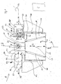
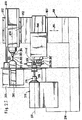
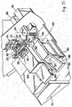
- the machine tool comprises a compact tool carrier trained tool carrier 32 to a bearing housing 58 which a tool carrier head 60 is rotatably mounted about an axis 62, which, in contrast to the tool carrier 34, preferably transversely to the X / Z plane 56 runs perpendicular to this.
- the bearing housing 58 is provided with a Holding fork 64 provided, the two enclosing a space 66 between them Has arms 68 and 70, between which the tool carrier head 60 is held.
- the tool carrier head 60 is designed so that it is a the holding fork 68 facing top 72 and one of the holding fork 70 facing Bottom 74 has, which are parallel to each other and preferably run perpendicular to axis 62 and base surfaces one between them extending prismatic body 76 which form multiple sides, for example four sides 78a, 78b, 78c and 78d, formed by corresponding ones flat side surfaces, which preferably run parallel to the axis 62, preferably at least one pair facing each other Side surfaces, for example the side surfaces 78a and 78c or the side surfaces 78b and 78d, parallel to each other and in the case of a cuboid as a prismatic body 76 aligned in pairs perpendicular to each other are.
- the prismatic Body 76 Regardless of the shape of the prismatic body 76, however, are each other opposite sides 78, that is, for example, the side surfaces of the Pages 78a and 78c or the side faces of pages 78b and 78c, the prismatic Body 76 arranged at a distance A1 or A2 from each other, that is smaller than 6 times the maximum diameter of the workpiece holder 30 and thus smaller than 6 times a maximum diameter of the workpiece W in the work spindle 26.
- the distances A1, A2 are even smaller than 4 times the maximum diameter of the workpiece holder 30 and thus the maximum diameter of the workpiece W.
- the maximum extent of the prismatic body can preferably be adjusted limit transverse to axis 62 to values that are less than 8 times of the maximum diameter of the workpiece holder.
- each side surface 78 can have one or more Tools can be assigned.
- pages 78a and 78c are heavy duty tools, in particular assigned heavy milling tools 80a and 80b, which are driven in rotation and preferably about a common axis of rotation 82 rotate, taking up and driving these heavy milling tools 80a and 80b further explanations follow.
- the axis of rotation 82 is such that it intersects the axis 62 around which the tool carrier head 60 relative to the bearing housing 58 is rotatable.
- the side 78b is on Assigned drilling tool 84, which is also driven in rotation and thus rotates about an axis of rotation 86.
- the axis of rotation 86 is arranged so that it axis 62 does not cut, but in an alignment plane running parallel to axis 62 88 is located at a distance from the axis 62.
- the alignment plane 88 placed so that it is perpendicular to the axis of rotation 82 of the heavy milling tools runs, and thus perpendicular to an alignment plane 90, which runs through the axis 62 and in which the axis of rotation 82 lies.
- Tools for example a tool holder 96 for stationary tools in the form of cutting plates 98a and 98b, such stationary ones Tools a main direction defined by the cutting edge geometry exhibit.
- the cutting plates 98a and 98b have main directions 100a and 100b, which on the one hand are aligned parallel to one another and on the other hand, for example, run such that the main direction 100a in the alignment plane 88 or a plane parallel to this and the Main direction 100b in an alignment plane 102 which is parallel and at a distance from Axis 62 and then preferably also runs parallel to alignment plane 88.
- a particularly favorable solution provides that the alignment levels 88 and 102 run symmetrically to a tool carrier head center plane 104, which in turn runs through the axis 62 and perpendicular to the alignment plane 90 stands.
- main directions opposing tools for example the main directions 94 and 100a in the same alignment plane, in this case the alignment plane 88.
- the different sides 78a and 78c and 78b and 78d are assigned in different directions.
- the main directions 92a and 92b close the sides 78a and 78c associated heavy milling tools 80a and 80b with the Main directions 94 or 100a or 100b of those assigned to sides 78b and 78d Tools 84, 98a, 98b, an angle of 90 ° with one another, thereby avoiding tools that are not in the working position collide with the workpiece W or parts of the work spindle 26, if one of the tools of the tool carrier head 60 on the workpiece W im Use is.
- main directions 100a and 100b can also be parallel be aligned with each other.
- one of the tools 80a or 80b or 84 assume that this with respect to the azimuthal direction 106 in both opposite directions Machining directions, so that the angle of> 60 ° between the Main direction 94 and the main direction 92a or the main direction 92b also should exist in both opposite directions.
- the tools are preferred arranged so that their main directions 92a, b, 94, 100a, b in lie on one level.
- all of the tools shown in FIG the heavy milling tools 80a and 80b are called the drilling tool 84 and the stationary tools 98a and 98b with their main directions 92a and 92b, 94 and 100a and 100b in a common tool plane 108, which in in this case is identical to the drawing level.
- a tool level 110 for example with Tool 80a, b, 84, 98a, b similarly designed tool and similar main directions provided, each with the tools can be used on the workpiece W, the tool plane 108 or 110 of which Spindle axis 28 is closest.
- the tool planes 108 or 110 are preferably arranged here such that on one side of the tool to be used Tool plane 108 or 110 the spindle axis lies while the other Tool plane 110 or 108 on the opposite of the spindle axis 28 Side of this tool level 108 or 110 runs.
- a tool from tool plane 108 for example the heavy milling tool 80a
- the tool carrier head 60 positioned such that the spindle axis 28 is always on the Tool plane 110 runs opposite side of the tool plane 108 and so that the spindle axis 28 maximally in the tool plane 108 runs itself.
- Tool carrier head 60 with the greatest possible flexibility of the used Tools that 60 on each side of the tool carrier head per level 88, 90, 102 tools at most in two in the direction of Axis 62 spaced tool planes 108 and 110 are arranged.
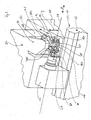
- each of its ends 122 and 124 has a receiving bore 126 or 128 as tool holders for a respective shaft 130a or 130b of the respective milling tool 80a or 80b.
- the spindle 120 is preferably near its ends 122 and 124 arranged pivot bearings 132 and 134 rotatable in the tool carrier head 60 supported and in each case carries a crown gear 138 in a central region 136, the teeth of a plane perpendicular to the axis of rotation 82 is facing so that the toothing 140 with a peripheral toothing 142 of a pinion 144 can be engaged, the axis of rotation 146 thereof coincides with axis 62.
- This pinion 144 is seated on a coaxial to the axis of rotation 146
- Drive shaft 148 which in an extension 150 of the tool carrier head 60th is stored, which is in one of the arms of the holding fork 64, for example the the upper arm 68 of the same and in turn by means of a pivot bearing 100 is rotatably mounted in this around the axis 62.
- the spindle 120 carries in its center Area 126 still a gear 162 with a peripheral toothing 164, compared to the toothing 140 radially inward to the axis of rotation 82 is offset and axially displaced and this toothing 164 is in engagement with a toothing 166 of a gear wheel 168 seated on the spindle 160, which in turn sits firmly on the spindle 160.
- the spindle 160 is similar or even identical to that Spindle 120, so that for further details on the comments on Spindle 120 can be referenced. Consequently, in the spindle 160 heavy-duty tools 80a 'and 80b' are also included, which around a common axis of rotation 82 'can be driven in rotation.
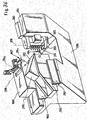
- the drilling tool 84 is arranged in a tool holder 170, the Tool holder body 172 is fixable on the tool carrier head 60 and in which one receiving the drilling tool 84 as a tool holder Spindle 174 is rotatably mounted.
- the tool holder body 172 is also provided with a drive finger 176 provided, in which a drive shaft 178 is rotatably mounted, the Drive shaft 178 a drive pinion arranged at the end of drive finger 176 180 carries.
- the drive finger 176 is in a receiving bore 182 of the tool carrier head 60 can be used, which is such that at in the receiving bore 182 inserted drive finger 176 the same end lying drive pinion 180 with the toothing 140 of the crown gear 138 is engaged and can be driven by this.
- the axis of rotation 184 of the drive pinion 180 and the drive shaft 178 to be arranged so that the axis of rotation 82 of the respective spindle 120 or 160 cuts and preferably in the respective tool plane 108 or 110.
- the tool holder 170 can either be constructed so that the Axis of rotation 184 and the axis of rotation 86 of the drilling tool 84 with one another aligned or spaced from each other, as shown in Fig. 3.
- the tool holder 170 For securely fixing the tool holder 170 is its tool holder body 172 additionally provided with an extension 188, which in a Receptacle 190 can be used in the tool carrier head 60 and can be fixed therein.
- the extension 188 is preferably arranged coaxially to the spindle 174, so that it can extend into the extension 188 and in this can still be supported by a pivot bearing 192, which is in addition to a pivot bearing 194 is provided for the spindle 174, the rotary bearing 194 the Spindle 174 in a mounting body 196 of the Tool holder body 172 is supported, from which the drive finger 176 and the extension 188 of the tool holder body 172 extend.
- the tool carrier head 60 Rotate in a controlled manner about the tool carrier head 60 about the axis of rotation 62 the tool carrier head 60 is provided with an extension 200, which is in an arm, for example the arm 70 of the holding fork 64 stretched in and is rotatably mounted in this via a pivot bearing 202.
- the extension 200 also carries a worm wheel 204 which is coaxial with the Axis 62 is arranged and is engaged with a worm 206 which around an axis 208 is rotatable, which is perpendicular to the axis of rotation 62 lying level.
- the worm 206 is seated on a swivel drive shaft 210, which extends in the arm 70 to the bearing housing 58 and with a drive motor arranged in the bearing housing 58 for Pivoting the tool carrier head 60 is coupled.
- the tool carrier head 60 must be positioned securely already with a self-locking gear, including for example that Worm gear 204 and worm 206 possible, especially if this is designed as a backlash-free gear.
- a fixation of the tool carrier head 60 provided in the holding fork 64 by a Hirth toothing 212 comprising a toothing ring which can be moved hydraulically in the direction of the axis 62 214, which is arranged coaxially with this and provided in the arm 68 of the holding fork 64 toothed ring 216 and a also arranged coaxially to these and firmly connected to the extension 150
- Tooth ring 218 is engageable or disengageable, thus to fix the extension 150 relative to the arm 68 or to fix it to solve.
- the Hirth toothing 212 preferably has a division which is one rotationally fixed fixing of the tool carrier head 60 relative to the holding fork 64 in 1.25 ° steps or an integer multiple of 1.25 ° steps allows so that not only rotations of the tool carrier head 60 relative to Holding fork 64 are possible by angles that allow the main direction 92a, b, 94, 100a, b each of the tools parallel to the X axis or parallel to the Z axis align, but also intermediate positions between such Alignments must be provided to finish machining complex workpieces can.
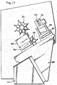
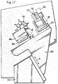
- Tool carrier head 60 can, as shown in FIGS. 5 to 10, the most varied Carry out machining of the workpiece W, in particular when the tool carrier head 60 is movable in the X direction and Z direction is that it has a side 78 facing a peripheral side 219 of the workpiece W. can be (Fig. 5 to 7) or with a side 78 of an end face 220 of the Workpiece W (Fig. 8, 9) can face.
- the drilling tool 84 can be used on the circumference of the workpiece W, a hole in any orientation to the X axis be introduced, that is, both a hole with an orientation the axis of rotation 86 in the X direction as well as a bore with a Alignment of the axis of rotation 76 at an angle other than 0 X-direction.
- the angle can be varied so far that the axis of rotation 86 is aligned parallel to the Z direction, for example at the end of the workpiece W drill holes.
- FIGS. 7 to 10 can also be used, for example the heavy milling tools 80a and 80b different processing of the workpiece W, for example, extensive machining with an orientation of the axis of rotation 82 parallel to the X direction, as in Fig. 7 shown or parallel to the Z direction, as shown in Fig. 8. Or Machining of the workpiece W on the end face over its entire end face 220, as shown in Fig. 9, or machining of the workpiece W with a Alignment of the axis of rotation 82 at acute angles to the X direction and Z direction, as shown in Fig. 10.
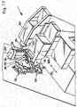
- FIGS. 5 to 10 it can also be seen in FIGS. 5 to 10 that at the same time with the machining of the workpiece W by one of the tools 80 or 84 of the tool carrier head still machining the workpiece W. by tools 51 of the turret 50 can be done without a Collision with tools 80a, b, 84, 98 of tool carrier head 60 he follows.
- 11 and 12 show the drive of the spindles 120 and 160 modified from the first embodiment.
- the gear wheels 162 seated on the spindles 120, 160 and 168 with each other so that the direction of rotation of one spindle 120, 160 opposite to the direction of rotation of the other spindle 160, 120.
- the coupled drive of the spindles takes place 120 and 160 also via the spindles 120 and 160 Gears 222 and 224, but these mesh with an idler gear 226, so that the two spindles 120 and 160 with this solution with the same Direction of rotation are driven.
- the intermediate wheel 226 also allows the distance between the spindles 120 and 160 advantageously enlarge without changing the diameter the gears 222 and 224 must be larger.
- the pinion 144 is direct arranged on a motor shaft of a drive motor 230, the drive motor 230 preferably on one facing away from the tool carrier head 60 Side of the arm 68 of the holding fork 64 is seated.
- the ability to drive large Drive the heavy milling tools 80 to be used to drive the same a reduction of 1: 4 takes place while driving for example of the drilling tools 84 selected a lower reduction in the ratio 1: 2 is, the drive motors 230 usually at a speed of 3000 to Work at 6000 rpm.
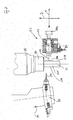
- a tool carrier head 60 ' In a third embodiment, shown in Figs. 13 and 14, comprises a tool carrier head 60 ', only in a tool plane 108 with their Main directions 92, 94 lying tools, for example the heavy ones Milling tools 80a and 80b and additionally the drilling tool 84 are available are.
- the lower arm 70 'of the holding fork 64' is Guide of the tool carrier head 60 'in turn also as a tool carrier trained and carries one to accommodate a rotating driven Tool 240 trained spindle 242, the rotating driven Tool 240 can be driven to rotate about an axis of rotation 244 and in particular that coinciding with the axis of rotation 244 Main direction 246 runs parallel to the X direction.
- the rotatingly driven tool 240 expediently stands here over a side 248a of the holding arm 70 'over.
- another side 248b of the holding arm 70 ' is preferably one stationary tool 250 associated with a tool holder 252 is held.
- the stationary tool 250 can be any tool.
- a preferred one Solution provides that this is a tailstock tip for one in a counter spindle represents held workpiece.
- a fourth embodiment of a machine tool according to the invention shown in Fig. 15 are those parts that start with the first Embodiment are identical, provided with the same reference numerals, so that with regard to the description of the full content of the first embodiment Can be referenced.
- the slides 40 'and 42' cannot be moved in a Y direction perpendicular to the X / Z plane, but in a Y 'direction that is inclined to the X / Z plane.
- carriages 36 'and 38' are also not parallel in the X direction movable to the X / Z plane, but in an X 'direction opposite to the X / Z plane is inclined.
- a machine tool is not only the work spindle 26 on the machine bed body 12 provided, but preferably on the same machine bed body 12 and on the spindle carrier side one positioned in alignment with the work spindle or positionable counter spindle 270, in their tool holder 272 the workpiece W with a first machined in the work spindle 26 Side W1 is recordable, for processing a second side W2.
- the Turret heads 50, 280 and 290 are preferably of identical design.
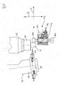
- the tool carrier head is 60 "not only on opposite sides 78a and 78c with rotatingly driven tools 80, but also on opposite sides 78b and 78d, for example are drilling tools 84a and 84b.
- the tool carrier head 60 "can thus between the spindle 26 and Counter spindle 270 are retracted that that recorded in the work spindle 26 Workpiece W on its first side W1 on its entire Front side 220 with the tool in the working position, for example can be edited with the drilling tool 84b, and that in the Counter spindle 270 picked up workpiece W on its second side W2 also on its entire end face 220 with the opposite Tool, such as the drilling tool 84a, can be drilled, this machining is possible without a collision with the turret heads 50 and 290 to bring about.
- the turret 280 is advantageously also replaced by a tool carrier head 60, which is designed, for example, like the tool carrier head 60 of the first embodiment.
- Each of the tool carrier heads 60 and 60 can be rotated about its axis 62 in such a way that that either the tools 80a, b, 84a, b with their main directions 92a, b, 94a, b aligned transverse to the Z axis or aligned transverse to the X axis Machining the workpiece W on the first W1 or the second side W2 can be used either on the circumference 219 or on the end face 220.
- a tool carrier head 60 is also assigned.
- the second side W2 is that received in the counter spindle 270 Workpiece W, for example, by two heavy milling tools 80a the tool carrier heads 60 'and 60 "which are assigned to the counter spindle 270 are editable.
- Fig. 19 shown in Fig. 19 are the work spindle 26 two tool carrier heads on opposite sides of the spindle axis 28 60 assigned and the counter spindle 270 are a tool carrier head 60 and a tool carrier head 60 "assigned so that by means of Tool carrier head 60 'is also possible, both on the first side W1 of the workpiece W held in the work spindle 26 as also on the face of the second side W2 of the counter spindle 270 held tool W to perform machining.
- a basic version of a ninth embodiment of an inventive Machine tool, in particular a lathe, shown in 20 comprises a machine frame, designated as a whole by 310 which a first spindle housing 312 is mounted, in which a first Working spindle 314 is rotatably mounted about a first spindle axis 316.
- the first work spindle 314 has a first receptacle 318 for a provided the first workpiece 320, which in the case shown as a End piece of a material rod 321 is formed.
- the material bar 321 runs through the first work spindle 314 and further from the first receptacle 318 to a long turning guide bush 322, which is held stationary on the machine frame 310.
- the first spindle housing 312 held on a carriage 324, which in a parallel to the first Spindle axis 316 running Z direction opposite the machine frame 310 is displaceable.
- first working spindle 314 On a side of the first working spindle 314 opposite Long turning guide sleeve 322 projects workpiece 320 into a first one Working space 330 into which, as shown in FIGS. 20 to 23, machining the workpiece 320 with two tool carriers 332 and 334 is possible on opposite sides of one through the first spindle axis 316 passing through plane 336 are arranged and parallel to an X direction perpendicular to the plane 336 in the direction of the Workpiece 320 are movable.
- one or both tool carriers 332, 334 additionally in the Y direction, that is, movable parallel to plane 336
- the tool carriers 332 and 334 are preferably a tool turret formed, which can be equipped with a variety of tools 342 and 344 with the tool turrets 332, 334 about turret axes 346 and 348, respectively are rotatable, which preferably run parallel to the first spindle axis 316, whereby the individual tools 342 and 344 in their the workpiece 320 each facing work position can be brought.
- the machining of out of the long turning guide bush 322 in the first work space 330 of projecting workpiece 320 takes place on the one hand by advancing tools 342 and 344 in the X direction and on the other hand by moving the workpiece 320 in the Z direction by moving the Working spindle 314 in the Z direction by means of the Z slide 324, the Work spindle 314 clamped the workpiece 320 with the receptacle 318 holds and drives rotating about the first spindle axis 316, while the Long turning guide bush 322 the first workpiece 320 only near the first Working space 330 in the radial direction to the first spindle axis 316 precise leads and absorbs the cutting forces.
- first workpiece 320 not only by means of the tool carrier 332 and 334 with the tools 342 and 344, but one To be able to carry out complete machining of workpiece 320 is on Machine frame 310 in addition to the work spindle 314 in a second Spindle housing 352 rotatably mounted second work spindle 354 is provided, which is aligned around a preferably parallel to the first spindle axis 316 second spindle axis 356 is rotatable.
- the second work spindle is 352 arranged so that they on one of the long-turning guide bush 322nd opposite side of the first working space 330 can be positioned.
- the second work spindle 354 is also with a second holder 358 for clamping a workpiece 360, the second workpiece 360 by parting the first workpiece 320 from the material bar 321 can be generated.
- the second spindle housing 352 sits on one designated as a whole by 362 Cross slide, which is in a transverse direction 364, also called the Y direction could be referred to, transversely to the second spindle axis 356 and transversely is movable relative to the machine frame 310 in the X direction, the Movability of the cross slide 362 in the transverse direction 364 the possibility includes the second work spindle 354 with the second spindle axis 356 Align coaxially to the first spindle axis 316 and thus the workpiece 320 to take over from the first recording 318.
- the second spindle housing 352 is additionally on a Z-slide 366 arranged, which sits on the cross slide 362 and a mobility of the second spindle housing 352 relative to the cross slide 362 in the direction parallel to the first spindle axis 316 and the second spindle axis 356 allowed.
- the second tool holder 372 on the front is preferably on one the second work spindle 354 opposite in its working position Side of the second work space 370 arranged, for example, the Tools 374 extend parallel to the second spindle axis 356 and preferably, 20 and 26 to 28, as row 376 as shown in FIGS a longitudinal direction 377, which are preferably parallel to the X direction runs.
- tool holder 372 itself compared to one of the cross slides 362 for the second work spindle 354 carrying bracket 380 is movable by means of an X-carriage 382, the X-carriage 382 preferably on a cheek extending in the X direction 384 of the console 380 is guided.
- Tool carrier 392 is provided, which on a work space 330 opposite side of the swivel guide bush 322 is arranged and carries tools 394, which on the first workpiece 320, for example for Machining of the front side 320S, can be used.
- the tool carrier 392 sits on a cross slide 402, which is movable relative to the console 380 in the transverse direction 364 and on this cross slide 402 is a Z slide 406, which in turn is the Tool carrier 392 carries.
- the cross slide 402 is, according to the invention, independent of the cross slide 362 for the second work spindle 354 in the transverse direction 364 the bracket 380 is movable so that the machining of the first workpiece 320, guided in the swivel guide bush 322 by means of the tools 394 independently in both the transverse direction 364 and the Z direction from machining the second workpiece 316 using the tools 374 can be done.
- the total Console 380 designed as an X-slide and as such relative to Machine frame 310 can be moved parallel to the X direction, as in FIGS. 25 and 26 shown.
- the workpiece then represents a second workpiece 360, which by method the second work spindle 354 in the transverse direction 364 through the tools 374 of the tool carrier 372 in the second work space 370 can be machined, primarily machining the second workpiece 360 in the area of its end face 360S in the second working space 370 can take place next to the first work space 330.
- This machining of the second workpiece 360 by means of the tools 374 is completely independent of the position of the console 380 in the X direction, since the Tool carrier 372 is held on the X-slide 382, which in turn is guided on the cheek 384 of the bracket 380 so as to be displaceable in the X direction that the tool carrier 372 thereby always relative movements to the console 380 and thus relative movements also to the second spindle axis 56 in the X direction that is immovable in the X direction relative to the console 380 is arranged so that the positions of the console 380 only in the X direction to the relative positions of the tools 394 of the first front Tool carrier 392 for machining the first workpiece 320 in the affect the way already described.
- a machine control 410 is provided to carry out the machining operations, which controls all axis movements precisely, i.e. in particular the movements of the Z slide 324 for the first work spindle 14, the tool carrier 332 and 334 for the tools 342 and 344, the cross slide 402 and the Z-carriage 406 and the X-carriage 380 for the first tool carrier 392 on the front with the tools 394, the cross slide 362 and the Z-slide 366 for the second work spindle 354 and of the X-slide 382 for the second tool holder 372 on the front the tools 374.
- the work spindles 314 and 354 are preferably not only drivable, but also as C-axes using the / machine control 410 precisely controllable.
- the lathe according to the invention can thereby be particularly advantageously control the axis movements for machining the second workpiece 360 by means of tools 374, namely the movements of the second front Tool carrier 372 along the X axis, the movements of the second Working spindle 354 in the direction of the transverse axis 364, which is also referred to as the Y axis could be, and in the direction of the Z axis as well as the rotation of the second workpiece 360 through the second work spindle 354 about a C axis are completely independent due to the design of the lathe, from the axis movements for machining the first workpiece 320, namely the movement of the first workpiece 320 in the Z direction by displacement the first work spindle 314, the movement of the tools 342 and 344 in the X direction, the movement of the tools 394 in the X direction by displacement the console 380, in the transverse direction by moving the cross slide 402 and in the Z direction by moving the cross slide 406 and around C-axis by suitable controlled turning of
- the displacement of the console 380 in the X direction still the advantage that a two-axis movement of the second work spindle 354 for coaxially positioning the second spindle axis 356 relative to the first spindle axis 316, namely along the transverse axis 364 and the X axis is available.
- Figs. 29 to 36 are those parts that correspond to those of the first embodiment are identical, provided with the same reference numerals, so that the full content of the comments on the first embodiment Can be referenced.
- the row 396b can be brought into the active position by tools 394b, while the row 936a of tools 394a is in the inactive position.
- the pivot axis 398 is formed as B axis controllable by the machine controller 410, as shown in FIG. 33, the possibility of using the tools, for example the tools 394a Row 396a into an angle with respect to the first spindle axis 316 Bring position so that oblique to the first spindle axis 316th directional machining of the first workpiece 320, for example bores, are realizable.
- the tools 394a, 394b preferably run in the radial direction Swivel axis 398 so that the cutting forces have a minimal torque with respect to the pivot axis 398.
- pivot axis 398 is oriented to be parallel to the longitudinal direction 397 of the rows 396a and 396b and also preferably parallel to level 336, so that the most collision-free processing possible of the first workpiece 320 with tools 394 and 395 of the tool carrier 392 in addition to the tools 342 and 344 can be realized.
- the pivot axis 378 is oriented so that it is parallel to Longitudinal direction 377 runs along which the tools forming the row 376 374 are aligned and also preferably parallel to the X direction, so that by pivoting the tools 374 about the pivot axis 378 whose position in the X direction relative to the second work spindle 354 is not changes.
- the tools 374 are preferably oriented so that they run radially to the pivot axis 378.
- the spindle housing is in the second embodiment 352 'of the second work spindle 354 also by the machine control 410 controllable pivot axis 359 pivotable, which preferably extends transversely to the pivot axis 378, so that the second overall Spindle axis 356 can be moved out of its orientation parallel to plane 336 is and thus in any angular position, for example in one acute angle to plane 336, can be positioned, for example, with the Tools 374, which are preferably all oriented parallel to plane 336, To be able to carry out machining at an angle to the second spindle axis 356.
- the ninth embodiment has the additional advantages that by the pivot axis 378 for the second front tool carrier 372, in particular their control as a B-axis by means of the machine control 410, together with the control of the second work spindle 354 as C-axis, through all usual machining of the second workpiece 360 a B axis of a lathe can be realized.
- the constructive solution can be particularly stable shape in that the tools 374 of the second tool carrier preferably extend radially to the pivot axis 378 so that the on this machining forces a slight, if not disappearing Apply torque to the pivot axis 378 so that it is mechanically limited effort is sufficiently stiff.
- the pivot axis 378 is preferably implemented such that at least one Pivotal movement of the second front tool carrier 392 'by one Angle of 90 ° can be realized.
- the ninth embodiment also has the provision of Pivot axis 398 for the first front tool carrier 392 the advantage that the number of tools can be used by the provision of Multiply two rows 396a and 396b of tools 394a and 394b, respectively leaves.
- the first tool carrier 392 'on the front is also preferably around the Swivel axis 398 can be swiveled at an angle of at least 90 °.
- pivot axis 359 also creates for the second work spindle 314 the advantage of setting a further inclination between the Tools 374 of the second front tool carrier 372 and the second workpiece 360 so that for finishing the second workpieces 360 highly complex machining is also possible.
Applications Claiming Priority (4)
| Application Number | Priority Date | Filing Date | Title |
|---|---|---|---|
| DE10130760 | 2001-06-22 | ||
| DE10130760A DE10130760A1 (de) | 2001-06-22 | 2001-06-22 | Drehmaschine |
| DE2002113778 DE10213778A1 (de) | 2002-03-22 | 2002-03-22 | Werkzeugmaschine |
| DE10213778 | 2002-03-22 |
Publications (2)
| Publication Number | Publication Date |
|---|---|
| EP1270145A2 true EP1270145A2 (fr) | 2003-01-02 |
| EP1270145A3 EP1270145A3 (fr) | 2004-02-11 |
Family
ID=26009588
Family Applications (1)
| Application Number | Title | Priority Date | Filing Date |
|---|---|---|---|
| EP02013041A Withdrawn EP1270145A3 (fr) | 2001-06-22 | 2002-06-13 | Machine outil avec porte-outil rotative pour plusieurs outils |
Country Status (1)
| Country | Link |
|---|---|
| EP (1) | EP1270145A3 (fr) |
Cited By (13)
| Publication number | Priority date | Publication date | Assignee | Title |
|---|---|---|---|---|
| WO2008016076A1 (fr) | 2006-08-04 | 2008-02-07 | Citizen Holdings Co., Ltd. | Ensemble combiné de tour de transformation et son support porte-outil |
| ITVR20080082A1 (it) * | 2008-07-25 | 2010-01-26 | Socomac S R L | Dispositivo automatizzato per la lavorazione di colonne, pilastri e angolari in genere |
| DE102009038403A1 (de) * | 2009-08-24 | 2011-03-31 | Oliver Schmid | Werkzeugeinsatz für eine Maschine, insbesondere für einen Werkzeugrevolver einer Drehmaschine, Verfahren zum Betätigen eines Werkzeugeinsatzes und Maschine mit einem Werkzeugeinsatz |
| ITMO20100312A1 (it) * | 2010-11-05 | 2012-05-06 | Sir Soc Italiana Resine Spa | Cella per la lavorazione automatizzata di lame |
| DE102014113204A1 (de) * | 2014-09-12 | 2016-03-17 | Index-Werke Gmbh & Co. Kg Hahn & Tessky | Werkzeugmaschine |
| EP3064297A1 (fr) * | 2015-03-03 | 2016-09-07 | Tornos SA | Equipement à accessoire amovible et ensemble pour tour d'usinage, et tour d'usinage à commande numérique |
| EP3183095A4 (fr) * | 2014-08-22 | 2018-12-05 | Superior Industries International, Inc. | Appareil et procédé d'usinage d'une pièce |
| CN110315352A (zh) * | 2019-08-13 | 2019-10-11 | 东莞市鑫屹机械设备有限公司 | 一种可拆卸式数控取丝机床 |
| JP2019198909A (ja) * | 2018-05-15 | 2019-11-21 | 株式会社ツガミ | 工作機械 |
| CN111975070A (zh) * | 2020-08-21 | 2020-11-24 | 新昌白云机床设备有限公司 | 一种轴承套圈双主轴三刀架车削机床 |
| EP3782784A1 (fr) * | 2019-08-20 | 2021-02-24 | Jingwei Systemtechnik Ltd. | Tête de machine de coupe et machine de coupe associée |
| EP4049786A1 (fr) * | 2021-02-26 | 2022-08-31 | PITTLER T&S GmbH | Dispositif et procédé d'usinage d'une pièce |
| IT202100031547A1 (it) * | 2021-12-16 | 2023-06-16 | Scm Group Spa | Dispositivo operativo con uscite a velocità di rotazione differenziate e macchina utensile comprendente tale dispositivo operativo |
Families Citing this family (1)
| Publication number | Priority date | Publication date | Assignee | Title |
|---|---|---|---|---|
| CN210132298U (zh) * | 2019-06-25 | 2020-03-10 | 苏州迈卡孚工业科技有限公司 | 一种可快速更换的工业刀具 |
Citations (3)
| Publication number | Priority date | Publication date | Assignee | Title |
|---|---|---|---|---|
| EP0614724A2 (fr) * | 1993-03-10 | 1994-09-14 | MAX RHODIUS GmbH | Machine-outil |
| DE10019669A1 (de) * | 2000-04-19 | 2001-10-31 | Heckert Werkzeugmaschinen Gmbh | Verfahren und Werkzeugmaschine zur Bearbeitung von Werkstücken |
| EP1193027A2 (fr) * | 2000-09-29 | 2002-04-03 | Traub Drehmaschinen GmbH | Tour |
-
2002
- 2002-06-13 EP EP02013041A patent/EP1270145A3/fr not_active Withdrawn
Patent Citations (3)
| Publication number | Priority date | Publication date | Assignee | Title |
|---|---|---|---|---|
| EP0614724A2 (fr) * | 1993-03-10 | 1994-09-14 | MAX RHODIUS GmbH | Machine-outil |
| DE10019669A1 (de) * | 2000-04-19 | 2001-10-31 | Heckert Werkzeugmaschinen Gmbh | Verfahren und Werkzeugmaschine zur Bearbeitung von Werkstücken |
| EP1193027A2 (fr) * | 2000-09-29 | 2002-04-03 | Traub Drehmaschinen GmbH | Tour |
Cited By (22)
| Publication number | Priority date | Publication date | Assignee | Title |
|---|---|---|---|---|
| EP2428295A1 (fr) | 2006-08-04 | 2012-03-14 | Citizen Holdings Co., Ltd. | Porte-outil |
| US8297158B2 (en) | 2006-08-04 | 2012-10-30 | Citizen Holdings Co., Ltd. | Combined processing lathe and its tool post |
| JP5100652B2 (ja) * | 2006-08-04 | 2012-12-19 | シチズンホールディングス株式会社 | 複合加工旋盤とその刃物台 |
| CN103223504A (zh) * | 2006-08-04 | 2013-07-31 | 西铁城控股株式会社 | 刀架和复合加工车床 |
| CN103223504B (zh) * | 2006-08-04 | 2015-09-02 | 西铁城控股株式会社 | 刀架和复合加工车床 |
| WO2008016076A1 (fr) | 2006-08-04 | 2008-02-07 | Citizen Holdings Co., Ltd. | Ensemble combiné de tour de transformation et son support porte-outil |
| ITVR20080082A1 (it) * | 2008-07-25 | 2010-01-26 | Socomac S R L | Dispositivo automatizzato per la lavorazione di colonne, pilastri e angolari in genere |
| DE102009038403A1 (de) * | 2009-08-24 | 2011-03-31 | Oliver Schmid | Werkzeugeinsatz für eine Maschine, insbesondere für einen Werkzeugrevolver einer Drehmaschine, Verfahren zum Betätigen eines Werkzeugeinsatzes und Maschine mit einem Werkzeugeinsatz |
| ITMO20100312A1 (it) * | 2010-11-05 | 2012-05-06 | Sir Soc Italiana Resine Spa | Cella per la lavorazione automatizzata di lame |
| EP3183095A4 (fr) * | 2014-08-22 | 2018-12-05 | Superior Industries International, Inc. | Appareil et procédé d'usinage d'une pièce |
| DE102014113204A1 (de) * | 2014-09-12 | 2016-03-17 | Index-Werke Gmbh & Co. Kg Hahn & Tessky | Werkzeugmaschine |
| EP3064297A1 (fr) * | 2015-03-03 | 2016-09-07 | Tornos SA | Equipement à accessoire amovible et ensemble pour tour d'usinage, et tour d'usinage à commande numérique |
| US10099293B2 (en) | 2015-03-03 | 2018-10-16 | Tornos Sa | Equipment with a detachable accessory and assembly for a machining lathe, and machining lathe with digital control |
| JP2019198909A (ja) * | 2018-05-15 | 2019-11-21 | 株式会社ツガミ | 工作機械 |
| JP7036662B2 (ja) | 2018-05-15 | 2022-03-15 | 株式会社ツガミ | 工作機械 |
| CN110315352A (zh) * | 2019-08-13 | 2019-10-11 | 东莞市鑫屹机械设备有限公司 | 一种可拆卸式数控取丝机床 |
| EP3782784A1 (fr) * | 2019-08-20 | 2021-02-24 | Jingwei Systemtechnik Ltd. | Tête de machine de coupe et machine de coupe associée |
| CN111975070A (zh) * | 2020-08-21 | 2020-11-24 | 新昌白云机床设备有限公司 | 一种轴承套圈双主轴三刀架车削机床 |
| EP4049786A1 (fr) * | 2021-02-26 | 2022-08-31 | PITTLER T&S GmbH | Dispositif et procédé d'usinage d'une pièce |
| WO2022180223A1 (fr) * | 2021-02-26 | 2022-09-01 | Pittler T&S Gmbh | Dispositif et procédé d'usinage d'une pièce à usiner, et produit programme d'ordinateur pour commander un dispositif d'usinage d'une pièce à usiner |
| IT202100031547A1 (it) * | 2021-12-16 | 2023-06-16 | Scm Group Spa | Dispositivo operativo con uscite a velocità di rotazione differenziate e macchina utensile comprendente tale dispositivo operativo |
| EP4197693A1 (fr) * | 2021-12-16 | 2023-06-21 | SCM Group S.p.A. | Dispositif d'usinage avec des sorties avec des vitesses de rotation différentes ainsi que machine-outil avec un tel dispositif |
Also Published As
| Publication number | Publication date |
|---|---|
| EP1270145A3 (fr) | 2004-02-11 |
Similar Documents
| Publication | Publication Date | Title |
|---|---|---|
| EP1193027B1 (fr) | Tour | |
| EP0538515B1 (fr) | Tour | |
| EP1027955B1 (fr) | Machine-outil | |
| EP1409182B1 (fr) | Machine-outil | |
| EP1180407B1 (fr) | Machine-outil | |
| DE19740379A1 (de) | Werkzeugrevolver für eine Werkzeugmaschine sowie Drehmaschine mit einem solchen Werkzeugrevolver | |
| EP2344301B1 (fr) | Machine-outil | |
| WO2006094712A2 (fr) | Machine-outil | |
| EP1270145A2 (fr) | Machine outil avec porte-outil rotative pour plusieurs outils | |
| EP2021149B1 (fr) | Machine-outil | |
| EP1752241B1 (fr) | Tour d'usinage | |
| DE10213778A1 (de) | Werkzeugmaschine | |
| DE3236356A1 (de) | Bearbeitungszentrum | |
| EP1160052B1 (fr) | Tour | |
| EP1281475B1 (fr) | Machine-outil avec deux broches pour pièces de travail et deux supports d'outils | |
| EP1025953B1 (fr) | Machine-outil | |
| EP2567782B1 (fr) | Tour multibroche | |
| DE19504370A1 (de) | Mehrspindeldrehmaschine | |
| EP0717669B1 (fr) | Dispositif d'usinage de pieces sur un tour automatique a commande numerique et tour automatique a commande numerique | |
| DE4022572A1 (de) | Drehmaschine mit doppelrevolver | |
| EP1291101A2 (fr) | Machine-outil avec broche porte-pièce et porte-outil multiple | |
| DE10027189A1 (de) | Drehmaschine | |
| DE19910953A1 (de) | Werkzeugmaschine |
Legal Events
| Date | Code | Title | Description |
|---|---|---|---|
| PUAI | Public reference made under article 153(3) epc to a published international application that has entered the european phase |
Free format text: ORIGINAL CODE: 0009012 |
|
| AK | Designated contracting states |
Kind code of ref document: A2 Designated state(s): AT BE CH CY DE DK ES FI FR GB GR IE IT LI LU MC NL PT SE TR |
|
| AX | Request for extension of the european patent |
Free format text: AL;LT;LV;MK;RO;SI |
|
| PUAL | Search report despatched |
Free format text: ORIGINAL CODE: 0009013 |
|
| AK | Designated contracting states |
Kind code of ref document: A3 Designated state(s): AT BE CH CY DE DK ES FI FR GB GR IE IT LI LU MC NL PT SE TR |
|
| AX | Request for extension of the european patent |
Extension state: AL LT LV MK RO SI |
|
| RIC1 | Information provided on ipc code assigned before grant |
Ipc: 7B 23Q 39/04 B Ipc: 7B 23Q 39/02 A |
|
| 17P | Request for examination filed |
Effective date: 20040720 |
|
| AKX | Designation fees paid |
Designated state(s): CH DE FR GB IT LI |
|
| 17Q | First examination report despatched |
Effective date: 20081126 |
|
| STAA | Information on the status of an ep patent application or granted ep patent |
Free format text: STATUS: THE APPLICATION IS DEEMED TO BE WITHDRAWN |
|
| 18D | Application deemed to be withdrawn |
Effective date: 20090407 |