EP1270090B1 - Improved vibration monitoring system and method - Google Patents
Improved vibration monitoring system and method Download PDFInfo
- Publication number
- EP1270090B1 EP1270090B1 EP02254473A EP02254473A EP1270090B1 EP 1270090 B1 EP1270090 B1 EP 1270090B1 EP 02254473 A EP02254473 A EP 02254473A EP 02254473 A EP02254473 A EP 02254473A EP 1270090 B1 EP1270090 B1 EP 1270090B1
- Authority
- EP
- European Patent Office
- Prior art keywords
- drive
- circuit
- current
- ultrasonic generator
- ultrasonic
- Prior art date
- Legal status (The legal status is an assumption and is not a legal conclusion. Google has not performed a legal analysis and makes no representation as to the accuracy of the status listed.)
- Expired - Lifetime
Links
- 238000012544 monitoring process Methods 0.000 title claims description 23
- 238000000034 method Methods 0.000 title claims description 9
- 239000013078 crystal Substances 0.000 claims description 15
- 238000003466 welding Methods 0.000 claims 1
- 230000000638 stimulation Effects 0.000 description 20
- 239000003990 capacitor Substances 0.000 description 18
- 230000008878 coupling Effects 0.000 description 3
- 238000010168 coupling process Methods 0.000 description 3
- 238000005859 coupling reaction Methods 0.000 description 3
- 238000001514 detection method Methods 0.000 description 3
- 238000006073 displacement reaction Methods 0.000 description 3
- 230000000694 effects Effects 0.000 description 2
- 238000007641 inkjet printing Methods 0.000 description 2
- 230000010355 oscillation Effects 0.000 description 2
- 230000010363 phase shift Effects 0.000 description 2
- 230000015572 biosynthetic process Effects 0.000 description 1
- 238000013467 fragmentation Methods 0.000 description 1
- 238000006062 fragmentation reaction Methods 0.000 description 1
- 238000003754 machining Methods 0.000 description 1
- 239000011159 matrix material Substances 0.000 description 1
- 238000004804 winding Methods 0.000 description 1
Images



Classifications
-
- B—PERFORMING OPERATIONS; TRANSPORTING
- B06—GENERATING OR TRANSMITTING MECHANICAL VIBRATIONS IN GENERAL
- B06B—METHODS OR APPARATUS FOR GENERATING OR TRANSMITTING MECHANICAL VIBRATIONS OF INFRASONIC, SONIC, OR ULTRASONIC FREQUENCY, e.g. FOR PERFORMING MECHANICAL WORK IN GENERAL
- B06B1/00—Methods or apparatus for generating mechanical vibrations of infrasonic, sonic, or ultrasonic frequency
- B06B1/02—Methods or apparatus for generating mechanical vibrations of infrasonic, sonic, or ultrasonic frequency making use of electrical energy
- B06B1/0207—Driving circuits
- B06B1/0223—Driving circuits for generating signals continuous in time
- B06B1/0238—Driving circuits for generating signals continuous in time of a single frequency, e.g. a sine-wave
- B06B1/0246—Driving circuits for generating signals continuous in time of a single frequency, e.g. a sine-wave with a feedback signal
-
- B—PERFORMING OPERATIONS; TRANSPORTING
- B41—PRINTING; LINING MACHINES; TYPEWRITERS; STAMPS
- B41J—TYPEWRITERS; SELECTIVE PRINTING MECHANISMS, i.e. MECHANISMS PRINTING OTHERWISE THAN FROM A FORME; CORRECTION OF TYPOGRAPHICAL ERRORS
- B41J2/00—Typewriters or selective printing mechanisms characterised by the printing or marking process for which they are designed
- B41J2/005—Typewriters or selective printing mechanisms characterised by the printing or marking process for which they are designed characterised by bringing liquid or particles selectively into contact with a printing material
- B41J2/01—Ink jet
- B41J2/015—Ink jet characterised by the jet generation process
- B41J2/02—Ink jet characterised by the jet generation process generating a continuous ink jet
- B41J2/025—Ink jet characterised by the jet generation process generating a continuous ink jet by vibration
Definitions
- the present invention relates to vibration monitoring and more particularly to monitoring the stimulation in any ultrasonic generator.
- Ultrasonic generators including ultrasonic cleaners, ultrasonic welders, ultrasonic machining, and continuous ink jet drop generators, are used for a variety of purposes. For example, in order to provide precise charging and deflection of drops in a continuous ink jet printer, it is important that the drop break-up process produce uniformly sized and timed drops. Drop generators for such printers produce the required drop formation by vibrating the orifices from which the ink emerges.
- Feedback transducers have been utilized for control of the stimulation amplitude and for tracking the resonance of the drop generator as discussed in U.S. Patent No. 5,384,583 , totally incorporated herein by reference. These feedback transducers work appropriately when the feedback signal has sufficient signal to noise.
- the use of a push-pull feedback system as discussed in that disclosure can effectively suppress noise due to charging transients or due to electronic coupling from the stimulation drive signal.
- the individual transducers can be placed close to each other so that the noise picked up by the two transducers are similar, allowing the noise to be canceled. Proper placement of the individual transducers can help suppress output signals from extraneous vibrational modes.
- US 3,868,698 A discloses a drive circuit for a stimulation transducer that suppresses generation of satellite drops in an ink jet recorder.
- the drive circuit is an oscillator which tracks the resonant frequency of the stimulation transducer. As the resonant frequency of the transducer changes during normal operation, the frequency of the driving signal also changes, so that the power output of the transducer remains essentially unchanged. This provides accurate regulation of the filament length for the jets being stimulated and unexpectedly also suppresses generation of satellite drops.
- the drive circuit comprises an amplifier, a load resistor and positive and negative feedback paths to the input terminals of the amplifier. The load resistor is incorporated within the negative feedback path as well as within the supply path for the stimulation transducer.
- the impedance of the stimulation transducer is minimum at the resonant frequency thereof, so that for any shifting of the resonant frequency there is an increase in the input impedance to the transducer. This produces a voltage variation across the load resister which in turn alters the negative feedback to the amplifier. Means are provided for adjusting the negative feedback signal so as to maintain the amplifier in a state of continuous oscillation.
- the frequency at which this oscillation occurs is the frequency at which the impedance of the transducer is minimum, and therefore the drive circuit tracks the resonant frequency of the stimulation transducer.
- US 6,083,191 A discloses an electrical apparatus for driving an ultrasonic piezoelectric crystal transducer in a surgical hand piece for the fragmentation and aspiration of tissue.
- the apparatus includes an electronic control loop in combination with a voltage source amplifier having an output which is connected to the piezoelectric crystal transducer with a tuning inductor in parallel.
- a control system for monitoring the control loop and a component for controlling tissue selectivity are also disclosed.
- piezoelectric drive crystals for both driving the drop generator and detecting the resulting vibration.
- the large capacitance of piezoelectric drive transducers when operated at high frequencies, can provide significant loading to the drive electronics. This can significantly limit the maximum drive amplitudes. It would, therefore, be desirable to have a means to allow for higher drive amplitudes, even with large capacitance levels of drive transducers.
- the present invention provides a means, such as a circuit, which uses the driving piezoelectric transducers to monitor the induced vibration or stimulation in an ultrasonic generator, such as the drop generator of an ink jet printing system.
- the present invention finds utility not just in the field of ink jet printing, but in other fields including monitoring ultrasonic cleaners and welders.
- Objects of the present invention include providing a method for monitoring the ultrasonic amplitude of an ultrasonic generator and providing a vibration monitoring system.
- the value r is the strain in the piezoelectric, corresponding to the displacement at the transducer.
- the clamped capacitance term, C p * v corresponds to the charge supplied to the capacitance of the transducer, which is independent of the motion of the piezoelectric.
- the drive signal 12 from the oscillator is supplied both to the piezoelectric transducer 14 and to a matching capacitor 16, whose capacitance equals the clamped capacitance of the piezoelectric transducer.
- a matching capacitor 16 On the ground side of the piezoelectric transducer and the matching capacitor are matched amplifiers 18.
- the matched charge amplifiers each produce a voltage output which is proportional to the charge on the input piezoelectric or capacitor. Since the capacitance of the matching capacitor has been set equal to the clamped capacitance of the piezoelectric, the charge on the matching capacitor will equal the charge on the piezoelectric due to the clamped capacitance.
- the voltage out of the lower charge amplifier will equal the voltage out of the upper amplifier produced by the clamped capacitance term of the sensor equation.
- the output from the difference amplifier 20 therefore, has removed the effect of the clamped capacitance, yielding an output which is directly proportional to the displacement produced by the transducer.
- this sensor actuator circuit 10 provides the desired output, to be used as a feedback signal 22, it has some shortcomings.
- the drop generator to be grounded by the feedback circuit forces the drop charging current to flow through this circuit.
- the charging current would therefore also be amplified by the amplifiers.
- the charging current would be expected to have an AC component at the stimulation frequency, this noise signal could not be readily filtered out.
- the resulting feedback signal would be modulated in conjunction with the print-catch duty cycle of the printhead.
- the drive signal since the drive signal must be supplied not only to the piezoelectric transducer but also to the matching capacitor, the drive electronics has an increased current load.
- transformer circuit embodiments in accordance with the present invention are illustrated.
- the drive voltage is supplied to both the drop generator and a matching capacitor.
- Transformers in the drive lines for both the piezoelectric and the matching capacitor couple the drive currents to their secondaries.
- the current produced in the secondaries flows through the resistors on the secondaries to produce a voltage across each proportional to the current.
- transformer circuits of the present invention therefore, eliminate the problem of needing to sink a lot of current into operational amplifiers.
- These transformer circuits also allow for the circuit to be moved from the ground side of the transducers to the drive side of the transducers. This eliminates the problems associated with attempts to electrically isolate the drop generator, and the problem of drop charging current being monitored and coupled into the stimulation feedback system.
- the circuit 24 of Fig. 2 requires the two transformers 32, 34 and the resistors 36, 38 to be matched. This circuit, however, still has the problem of loading the stimulation drive circuit. A second potential problem is the power drop through the resistors on the secondaries.
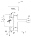
- the present invention proposes an alternative transformer circuit 26, illustrated in Fig. 3.
- the differential transformer circuit of Fig. 3 eliminates problems that may be encountered with the circuit 24 of Fig. 2.
- the differential transformer circuit uses a three leg transformer 40.
- the drive signal is supplied to the two primary legs of the transformer. These are connected in turn to the piezoelectric transducer 14 and the matching capacitor 42.
- the primary for the matching capacitor 42 leg is reversed so that if the current to the two primary windings are matched, there will be no current induced in the secondary. If the current to the piezoelectric transducer differs from that to the matched capacitor, the current in the output leg of the transformer will be proportional to the current difference of the primaries.
- the output current produces a voltage across the resistor 46, which is seen at the output 44. Since only a current related to the current difference is produced in the secondary, the power dumped into the resistor 46 is reduced.
- the piezoelectric transducer had a clamped capacitance of about 68 nf.
- the circuit in Fig. 3 makes use of a ten-to-one step up transformer 40.
- step up transformers is useful not only for increasing the output amplitude but also for stepping down the impedance seen in the primary leg of the transformers as a result of the resistance across the secondary.
- the 100 ohm resistor on the secondary produces only one ohm of impedance on the primaries.
- the circuit 26 includes an inductor 48 for power factor correction.
- the proper inductance value for a desired operating frequency can be obtained from an analysis of the circuit impedance.
- the inductance for which the imaginary term of the circuit impedance is zero at the operating frequency yields the desired power factor correction.
- the capacitive current seen by the drive source can be reduced. As a result, the loading of the drive source is reduced.
- this stimulation monitor includes the power factor correcting inductor to reduce the current load on the drive circuit
- the differential transformer system can be used without this feature. This may be preferred where the capacitances are low, or where system is to be operated over a large frequency range.
- the output from differential transformer circuit 26 tracks the amplitude and phase of the vibrational velocity as the drive frequency and the ultrasonic loading of the drop generator are changed.
- a comparison of the output from the differential transformer is made with that from a push-pull feedback system, such as is disclosed and claimed in U.S. Patent No. 5,384,583 on the same drop generator, shows approximately 10 db higher from the differential transformer circuit than from a push-pull feedback system. Since the differential transformer circuit output is derived from the current going to all the drive crystals, it tends to suppress the detection of resonances which are not uniform down the length of the array. As a result, output gain and phase plots can show that the differential transformer is more successful at suppressing the detection of extraneous modes than push-pull feedback systems of the prior art.
- the differential transformer circuit of Fig. 3 provides an output which tracks the velocity at the piezoelectric transducer. If desired, the circuit can be made to track displacement. This can be accomplished by replacing the resistor 46 across the transformer secondary, in Fig. 3, with a capacitor 48, as shown in Fig. 4. This circuit 28 will produce a 90° phase shift between the drive signal and the feedback signal at the mechanical resonance of the transducer. The circuit of Fig. 3, on the other hand, produces a 0° phase shift between the drive signal and the feedback signal at the mechanical resonance of the transducer. The choice between these two circuits is based on the design of the control circuit, which will use the output from this vibration monitoring circuit.
- Fig. 5 shows such a push-pull configuration 50, symmetric around ground.
- the vibration monitoring circuits shown above all use capacitors matched to the clamped capacitance of the piezoelectric transducer.
- Fig. 6 shows an alternate embodiment in which the turns ratio of the two primaries are no longer one to one. This allows the capacitance of the matching capacitor to be scaled by the primary turns ratio relative to the clamped capacitance of the piezoelectric transducer. This can be useful allow smaller, more convenient matching capacitors to be used.
- the reduced current requirements to the transformer circuit may also reduce or eliminate the need for the power factor correcting inductor 48.
- transformer circuits particularly differential transformer circuits illustrated herein, is particularly useful for monitoring the vibration amplitude in drop generators for continuous ink jet printers.
- the circuits taught herein are also useful for monitoring the vibration amplitude in many other piezoelectrically driven vibrating systems. Such systems include ultrasonic welders and ultrasonic cleaners.
- the circuit can provide the amplitude and phase information that is desirable for locking the drive frequency onto resonance and for servo controlling the amplitude of vibration.
- this vibration monitoring circuit is preferred over the prior art for those applications where significant amounts of power are supplied to the piezoelectric transducers to produce a vibration. It is also preferred where it is not desirable or possible to insert the monitoring circuit on the ground side of the transducer.
Landscapes
- Engineering & Computer Science (AREA)
- Mechanical Engineering (AREA)
- Apparatuses For Generation Of Mechanical Vibrations (AREA)
- Measurement Of Mechanical Vibrations Or Ultrasonic Waves (AREA)
- Transducers For Ultrasonic Waves (AREA)
Description
- The present invention relates to vibration monitoring and more particularly to monitoring the stimulation in any ultrasonic generator.
- Vibration monitoring is useful in multiple systems and industries. Ultrasonic generators, including ultrasonic cleaners, ultrasonic welders, ultrasonic machining, and continuous ink jet drop generators, are used for a variety of purposes. For example, in order to provide precise charging and deflection of drops in a continuous ink jet printer, it is important that the drop break-up process produce uniformly sized and timed drops. Drop generators for such printers produce the required drop formation by vibrating the orifices from which the ink emerges.
- Feedback transducers have been utilized for control of the stimulation amplitude and for tracking the resonance of the drop generator as discussed in
U.S. Patent No. 5,384,583 , totally incorporated herein by reference. These feedback transducers work appropriately when the feedback signal has sufficient signal to noise. The use of a push-pull feedback system as discussed in that disclosure can effectively suppress noise due to charging transients or due to electronic coupling from the stimulation drive signal. - The individual transducers can be placed close to each other so that the noise picked up by the two transducers are similar, allowing the noise to be canceled. Proper placement of the individual transducers can help suppress output signals from extraneous vibrational modes.
- However, for some drop generator designs, it is not practical to place the transducer appropriately to suppress all the other extraneous modes. This might be a result of insufficient space to place the feedback transducers, or low output amplitudes on available surface space. For some drop generator designs, to effectively suppress the detection of extraneous modes would require placement of feedback transducers in the space already occupied by the drive transducers. This results from the need to place drive transducers in a particular pattern to suppress the exciting of undesirable modes.
- For such systems it would be desirable to employ the driving transducers as feedback transducers as well. While
U.S. Patent No. 3,868,698 makes use of the drive transducer impedance characteristics to track resonant frequency, it does not teach a means to monitor the vibration amplitude and phase for use in the control of the ink jet system. -
US 3,868,698 A discloses a drive circuit for a stimulation transducer that suppresses generation of satellite drops in an ink jet recorder. The drive circuit is an oscillator which tracks the resonant frequency of the stimulation transducer. As the resonant frequency of the transducer changes during normal operation, the frequency of the driving signal also changes, so that the power output of the transducer remains essentially unchanged. This provides accurate regulation of the filament length for the jets being stimulated and unexpectedly also suppresses generation of satellite drops. The drive circuit comprises an amplifier, a load resistor and positive and negative feedback paths to the input terminals of the amplifier. The load resistor is incorporated within the negative feedback path as well as within the supply path for the stimulation transducer. In general the impedance of the stimulation transducer is minimum at the resonant frequency thereof, so that for any shifting of the resonant frequency there is an increase in the input impedance to the transducer. This produces a voltage variation across the load resister which in turn alters the negative feedback to the amplifier. Means are provided for adjusting the negative feedback signal so as to maintain the amplifier in a state of continuous oscillation. The frequency at which this oscillation occurs is the frequency at which the impedance of the transducer is minimum, and therefore the drive circuit tracks the resonant frequency of the stimulation transducer. -
US 6,083,191 A discloses an electrical apparatus for driving an ultrasonic piezoelectric crystal transducer in a surgical hand piece for the fragmentation and aspiration of tissue. The apparatus includes an electronic control loop in combination with a voltage source amplifier having an output which is connected to the piezoelectric crystal transducer with a tuning inductor in parallel. A control system for monitoring the control loop and a component for controlling tissue selectivity are also disclosed. - It would be desirable to have an effective means to employ the piezoelectric drive crystals for both driving the drop generator and detecting the resulting vibration. Additionally, the large capacitance of piezoelectric drive transducers, when operated at high frequencies, can provide significant loading to the drive electronics. This can significantly limit the maximum drive amplitudes. It would, therefore, be desirable to have a means to allow for higher drive amplitudes, even with large capacitance levels of drive transducers.
- The present invention provides a means, such as a circuit, which uses the driving piezoelectric transducers to monitor the induced vibration or stimulation in an ultrasonic generator, such as the drop generator of an ink jet printing system. The present invention finds utility not just in the field of ink jet printing, but in other fields including monitoring ultrasonic cleaners and welders.
- Objects of the present invention include providing a method for monitoring the ultrasonic amplitude of an ultrasonic generator and providing a vibration monitoring system. These objects are achieved by the present invention as defined by the appended claims.
-
- Fig. 1 illustrates a prior art circuit for a self-sensing transducer;
- Fig. 2 illustrates a transformer circuit for stimulation monitoring, in accordance with the present invention;
- Fig. 3 illustrates a differential transformer circuit for stimulation monitoring, in accordance with the present invention;
- Fig. 4 illustrates an alternative embodiment of a differential transformer circuit for stimulation monitoring, in accordance with the present invention;
- Fig. 5 illustrates yet another alternative embodiment of a differential transformer circuit for stimulation monitoring, in accordance with the present invention; and
- Fig. 6 illustrates yet another alternative embodiment of a differential transformer circuit for stimulation monitoring, in accordance with the present invention.
- The present invention uses a method for monitoring the stimulation amplitude that makes use of the sensor equation for piezoelectric transducers:

where, ΘT is the piezoelectric coupling matrix; q is the charge produced by or supplied to the piezoelectric transducer; Cp is the clamped capacitance of the piezoelectric; and ν is the time derivative of the voltage. The value r is the strain in the piezoelectric, corresponding to the displacement at the transducer. The clamped capacitance term, Cp * v , corresponds to the charge supplied to the capacitance of the transducer, which is independent of the motion of the piezoelectric. - From the above equation, it is seen that if the clamped capacitance term could be eliminated from the right side of the equation, then the current would be directly proportional to the velocity. To accomplish this, the circuit of Fig. 1 is proposed.
- As shown in the
prior art circuit 10 of Fig. 1, thedrive signal 12 from the oscillator is supplied both to thepiezoelectric transducer 14 and to amatching capacitor 16, whose capacitance equals the clamped capacitance of the piezoelectric transducer. On the ground side of the piezoelectric transducer and the matching capacitor are matchedamplifiers 18. The matched charge amplifiers each produce a voltage output which is proportional to the charge on the input piezoelectric or capacitor. Since the capacitance of the matching capacitor has been set equal to the clamped capacitance of the piezoelectric, the charge on the matching capacitor will equal the charge on the piezoelectric due to the clamped capacitance. As the charge on the matching capacitor will equal the charge on the piezoelectric due to the clamped capacitance, the voltage out of the lower charge amplifier will equal the voltage out of the upper amplifier produced by the clamped capacitance term of the sensor equation. The output from thedifference amplifier 20, therefore, has removed the effect of the clamped capacitance, yielding an output which is directly proportional to the displacement produced by the transducer. - While this
sensor actuator circuit 10 provides the desired output, to be used as afeedback signal 22, it has some shortcomings. First, when used for the stimulation drive system, the inputs for each of the charge amplifiers will have to handle quite a large amount of current. Obtaining the desired operational amplifiers which can handle the current can be difficult. Second, the circuit monitors the current on the ground side of the transducers. For a drop generator, this would require either that the piezoelectrics be isolated from the drop generator or that the drop generator be isolated from the rest of the printhead. Since electrically isolating the piezoelectrics from the drop generator can have a negative effect on the acoustic coupling, this would imply electrically isolating the drop generator. Third, requiring the drop generator to be grounded by the feedback circuit forces the drop charging current to flow through this circuit. The charging current would therefore also be amplified by the amplifiers. As the charging current would be expected to have an AC component at the stimulation frequency, this noise signal could not be readily filtered out. The resulting feedback signal would be modulated in conjunction with the print-catch duty cycle of the printhead. Fourth, since the drive signal must be supplied not only to the piezoelectric transducer but also to the matching capacitor, the drive electronics has an increased current load. - The problems associated with the typical circuit for self-sensing actuators can be overcome by a transformer system proposed by the present invention. Referring to Figs. 2-5, transformer circuit embodiments in accordance with the present invention are illustrated. In
circuits - The transformer circuits of the present invention, therefore, eliminate the problem of needing to sink a lot of current into operational amplifiers. These transformer circuits also allow for the circuit to be moved from the ground side of the transducers to the drive side of the transducers. This eliminates the problems associated with attempts to electrically isolate the drop generator, and the problem of drop charging current being monitored and coupled into the stimulation feedback system.
- In addition to having a
capacitor 16 which is matched to the clamped capacitance of the piezoelectric 14, thecircuit 24 of Fig. 2 requires the twotransformers 32, 34 and theresistors - Therefore, the present invention proposes an
alternative transformer circuit 26, illustrated in Fig. 3. The differential transformer circuit of Fig. 3 eliminates problems that may be encountered with thecircuit 24 of Fig. 2. In Fig. 3, the differential transformer circuit uses a threeleg transformer 40. The drive signal is supplied to the two primary legs of the transformer. These are connected in turn to thepiezoelectric transducer 14 and the matchingcapacitor 42. The primary for the matchingcapacitor 42 leg is reversed so that if the current to the two primary windings are matched, there will be no current induced in the secondary. If the current to the piezoelectric transducer differs from that to the matched capacitor, the current in the output leg of the transformer will be proportional to the current difference of the primaries. The output current produces a voltage across theresistor 46, which is seen at theoutput 44. Since only a current related to the current difference is produced in the secondary, the power dumped into theresistor 46 is reduced. In this figure, the piezoelectric transducer had a clamped capacitance of about 68 nf. - The circuit in Fig. 3, makes use of a ten-to-one step up
transformer 40. The use of step up transformers is useful not only for increasing the output amplitude but also for stepping down the impedance seen in the primary leg of the transformers as a result of the resistance across the secondary. With the ten to one step up transformer, the 100 ohm resistor on the secondary produces only one ohm of impedance on the primaries. - Continuing with Fig. 3, to reduce the current load on the oscillator, the
circuit 26 includes aninductor 48 for power factor correction. The proper inductance value for a desired operating frequency can be obtained from an analysis of the circuit impedance. The inductance for which the imaginary term of the circuit impedance is zero at the operating frequency yields the desired power factor correction. With the appropriate inductance, the capacitive current seen by the drive source can be reduced. As a result, the loading of the drive source is reduced. - While the preferred embodiment of this stimulation monitor includes the power factor correcting inductor to reduce the current load on the drive circuit, the differential transformer system can be used without this feature. This may be preferred where the capacitances are low, or where system is to be operated over a large frequency range.
- The output from
differential transformer circuit 26 tracks the amplitude and phase of the vibrational velocity as the drive frequency and the ultrasonic loading of the drop generator are changed. A comparison of the output from the differential transformer is made with that from a push-pull feedback system, such as is disclosed and claimed inU.S. Patent No. 5,384,583 on the same drop generator, shows approximately 10 db higher from the differential transformer circuit than from a push-pull feedback system. Since the differential transformer circuit output is derived from the current going to all the drive crystals, it tends to suppress the detection of resonances which are not uniform down the length of the array. As a result, output gain and phase plots can show that the differential transformer is more successful at suppressing the detection of extraneous modes than push-pull feedback systems of the prior art. - The differential transformer circuit of Fig. 3 provides an output which tracks the velocity at the piezoelectric transducer. If desired, the circuit can be made to track displacement. This can be accomplished by replacing the
resistor 46 across the transformer secondary, in Fig. 3, with acapacitor 48, as shown in Fig. 4. Thiscircuit 28 will produce a 90° phase shift between the drive signal and the feedback signal at the mechanical resonance of the transducer. The circuit of Fig. 3, on the other hand, produces a 0° phase shift between the drive signal and the feedback signal at the mechanical resonance of the transducer. The choice between these two circuits is based on the design of the control circuit, which will use the output from this vibration monitoring circuit. - For some applications it is desirable for issues of noise pick up to provide a balanced output from the monitoring circuit. Fig. 5 shows such a push-
pull configuration 50, symmetric around ground. - The vibration monitoring circuits shown above all use capacitors matched to the clamped capacitance of the piezoelectric transducer. Fig. 6 shows an alternate embodiment in which the turns ratio of the two primaries are no longer one to one. This allows the capacitance of the matching capacitor to be scaled by the primary turns ratio relative to the clamped capacitance of the piezoelectric transducer. This can be useful allow smaller, more convenient matching capacitors to be used. The reduced current requirements to the transformer circuit may also reduce or eliminate the need for the power
factor correcting inductor 48. - The concept of transformer circuits, particularly differential transformer circuits illustrated herein, is particularly useful for monitoring the vibration amplitude in drop generators for continuous ink jet printers. However, the circuits taught herein are also useful for monitoring the vibration amplitude in many other piezoelectrically driven vibrating systems. Such systems include ultrasonic welders and ultrasonic cleaners. For both these applications, the circuit can provide the amplitude and phase information that is desirable for locking the drive frequency onto resonance and for servo controlling the amplitude of vibration. In general, this vibration monitoring circuit is preferred over the prior art for those applications where significant amounts of power are supplied to the piezoelectric transducers to produce a vibration. It is also preferred where it is not desirable or possible to insert the monitoring circuit on the ground side of the transducer.
Claims (10)
- A method for monitoring the ultrasonic amplitude of an ultrasonic generator, comprising the steps of:employing piezoelectric drive crystals (14) to drive the ultrasonic generator, the drive crystals having an associated oscillator (12);using at least one differential transformer circuit (32-34, 40) to compare current to the drive crystals (14) to a matched reference circuit (16, 42) and tocancel capacitive current from the piezoelectric drive crystals based on the comparison of the current to the drive crystals to the matched reference circuit, whereby a resulting output signal (22, 44) provides a direct measure of the ultrasonic amplitude of the ultrasonic generator.
- A method as claimed in claim 1 wherein the at least one transformer circuit comprises a differential transformer (40).
- A method as claimed in claim 1 further comprising the step of using a power factor correcting inductor (15) to reduce load on the oscillator (12).
- A method as claimed in claim 1 further comprising the step of adding an inductor (15) in parallel to the at least one transformer circuit (40) to reduce loading of the oscillator (12).
- A method as claimed in claim 1 wherein the ultrasonic generator comprises a drop generator for a continuous ink jet printer.
- A vibration monitoring system for an ultrasonic generator, the system comprising:piezoelectric drive crystals (14) to drive the ultrasonic generator, the drive crystals having an associated oscillator (12); anda reference circuit matched to the drive crystals;characterized by, a differential transformer circuit (32, 34; 40) that cancels capacitive current from the piezoelectric drive crystals based on the comparison of the current to the drive crystals to the matched reference circuit to produce an electrical signal having a characteristic that is proportional to the difference between the current to the drive crystals and the current to the matched reference circuit (42) to providea direct measure (44) of vibration amplitude and phase of the ultrasonic generator.
- A system as claimed in claim 6 further comprising a power factor correcting inductor (15) to reduce load on the oscillator (12).
- A system as claimed in claim 6 further comprising an inductor (15) in parallel with the differential transformer circuit to reduce loading of the oscillator (12).
- A system as claimed in claim 6 wherein the ultrasonic generator comprises a drop generator for a continuous ink jet printer.
- A system as claimed in claim 6 wherein the ultrasonic generator comprises an ultrasonic welding horn.
Applications Claiming Priority (2)
| Application Number | Priority Date | Filing Date | Title |
|---|---|---|---|
| US893111 | 1986-08-04 | ||
| US09/893,111 US6469418B1 (en) | 2001-06-27 | 2001-06-27 | Vibration monitoring system and method |
Publications (2)
| Publication Number | Publication Date |
|---|---|
| EP1270090A1 EP1270090A1 (en) | 2003-01-02 |
| EP1270090B1 true EP1270090B1 (en) | 2007-09-26 |
Family
ID=25401047
Family Applications (1)
| Application Number | Title | Priority Date | Filing Date |
|---|---|---|---|
| EP02254473A Expired - Lifetime EP1270090B1 (en) | 2001-06-27 | 2002-06-26 | Improved vibration monitoring system and method |
Country Status (4)
| Country | Link |
|---|---|
| US (1) | US6469418B1 (en) |
| EP (1) | EP1270090B1 (en) |
| JP (1) | JP4122180B2 (en) |
| DE (1) | DE60222610T2 (en) |
Families Citing this family (6)
| Publication number | Priority date | Publication date | Assignee | Title |
|---|---|---|---|---|
| US7262543B2 (en) * | 2004-09-08 | 2007-08-28 | United States Of America As Represented By The Administrator Of The National Aeronautics And Space Administration | System and method for monitoring piezoelectric material performance |
| DE102006046593B4 (en) * | 2006-09-30 | 2009-12-10 | Deutsches Zentrum für Luft- und Raumfahrt e.V. | Device for reducing vibrations of a structure |
| KR101170855B1 (en) * | 2006-12-11 | 2012-08-02 | 삼성전기주식회사 | Apparatus and method detecting for operating of a piezo inkjet head |
| US9528815B2 (en) | 2013-02-08 | 2016-12-27 | Hamilton Sundstrand Corporation | Transformer based sensor arrangement |
| US10086217B2 (en) | 2014-07-25 | 2018-10-02 | Covidien Lp | Electrosurgical ultrasonic vessel sealing and dissecting system |
| US11849643B2 (en) * | 2021-03-30 | 2023-12-19 | Cirrus Logic Inc. | Circuitry for estimating displacement of a piezoelectric transducer |
Family Cites Families (9)
| Publication number | Priority date | Publication date | Assignee | Title |
|---|---|---|---|---|
| US3727112A (en) * | 1969-08-29 | 1973-04-10 | Surgical Design Corp | Generator for producing ultrasonic energy |
| US3868698A (en) * | 1973-10-24 | 1975-02-25 | Mead Corp | Stimulation control apparatus for an ink jet recorder |
| US3931533A (en) * | 1974-05-30 | 1976-01-06 | Sybron Corporation | Ultrasonic signal generator |
| ES2104953T3 (en) * | 1992-02-07 | 1997-10-16 | Valleylab Inc | SURGICAL DEVICE ULTRASONIC. |
| FR2721154B1 (en) * | 1994-06-08 | 1996-07-05 | Moulinex Sa | Power circuit of a piezoelectric motor. |
| US6084363A (en) * | 1997-01-17 | 2000-07-04 | Minolta Co., Ltd. | Drive pulse generating apparatus for drive device using electromechanical transducer |
| WO1998051255A1 (en) * | 1997-05-15 | 1998-11-19 | Matsushita Electric Works, Ltd. | Ultrasonic device |
| US5976316A (en) * | 1998-05-15 | 1999-11-02 | 3M Innovative Properties Company | Non-nodal mounting system for acoustic horn |
| JP2001016877A (en) * | 1999-06-25 | 2001-01-19 | Asmo Co Ltd | Ultrasonic motor drive circuit |
-
2001
- 2001-06-27 US US09/893,111 patent/US6469418B1/en not_active Expired - Lifetime
-
2002
- 2002-06-26 EP EP02254473A patent/EP1270090B1/en not_active Expired - Lifetime
- 2002-06-26 DE DE60222610T patent/DE60222610T2/en not_active Expired - Lifetime
- 2002-06-27 JP JP2002188116A patent/JP4122180B2/en not_active Expired - Fee Related
Also Published As
| Publication number | Publication date |
|---|---|
| DE60222610T2 (en) | 2008-06-26 |
| JP4122180B2 (en) | 2008-07-23 |
| EP1270090A1 (en) | 2003-01-02 |
| US6469418B1 (en) | 2002-10-22 |
| DE60222610D1 (en) | 2007-11-08 |
| JP2003114147A (en) | 2003-04-18 |
Similar Documents
| Publication | Publication Date | Title |
|---|---|---|
| CA1070818A (en) | Sonic transducer and drive circuit | |
| EP0654889B1 (en) | Driving device for ultrasonic wave motor | |
| US5558477A (en) | Vibration damping system using active negative capacitance shunt circuit with piezoelectric reaction mass actuator | |
| US5900690A (en) | Apparatus and method for controlling an ultrasonic transducer | |
| US20030072462A1 (en) | Loudspeaker with large displacement motional feedback | |
| US3727112A (en) | Generator for producing ultrasonic energy | |
| US6765333B1 (en) | Power assistance device for an ultrasonic vibration dental handpiece | |
| EP0270819A3 (en) | Linear power control for ultrasonic probe with tuned reactance | |
| GB2124442A (en) | Ultrasonic transducer driving apparatus | |
| US4578650A (en) | Resonance drive oscillator circuit | |
| US6469418B1 (en) | Vibration monitoring system and method | |
| US5777425A (en) | Voltage converter for use with a piezoelectric transformer | |
| US4488439A (en) | Mass flow meter with vibration sensor | |
| US5384583A (en) | Ink jet stimulation monitoring | |
| US6624708B1 (en) | Active shunt capacitance cancelling oscillator circuit | |
| EP1004848B1 (en) | Angular velocity sensor | |
| US20020163675A1 (en) | Optical scanner driving apparatus and optical scanner driving method | |
| Imori et al. | A photomultiplier high voltage power supply incorporating a piezoelectric ceramic transformer | |
| EP0169064B1 (en) | Low voltage transformer coupled ink jet driver | |
| EP0624468B1 (en) | Improved ink jet stimulation monitoring | |
| EP1092446A3 (en) | Nebuliser | |
| JPH05269101A (en) | Nuclear magnetic resonance imaging system | |
| JPH09314054A (en) | Ultrasonic oscillator | |
| JPH0638554A (en) | Ultrasonic motor drive | |
| JPH0251380A (en) | Driving circuit for ultrasonic motor |
Legal Events
| Date | Code | Title | Description |
|---|---|---|---|
| PUAI | Public reference made under article 153(3) epc to a published international application that has entered the european phase |
Free format text: ORIGINAL CODE: 0009012 |
|
| AK | Designated contracting states |
Kind code of ref document: A1 Designated state(s): AT BE CH CY DE DK ES FI FR GB GR IE IT LI LU MC NL PT SE TR |
|
| AX | Request for extension of the european patent |
Free format text: AL;LT;LV;MK;RO;SI |
|
| 17P | Request for examination filed |
Effective date: 20030702 |
|
| AKX | Designation fees paid |
Designated state(s): DE FR GB |
|
| 17Q | First examination report despatched |
Effective date: 20040329 |
|
| RAP1 | Party data changed (applicant data changed or rights of an application transferred) |
Owner name: EASTMAN KODAK COMPANY |
|
| GRAP | Despatch of communication of intention to grant a patent |
Free format text: ORIGINAL CODE: EPIDOSNIGR1 |
|
| GRAS | Grant fee paid |
Free format text: ORIGINAL CODE: EPIDOSNIGR3 |
|
| GRAA | (expected) grant |
Free format text: ORIGINAL CODE: 0009210 |
|
| AK | Designated contracting states |
Kind code of ref document: B1 Designated state(s): DE FR GB |
|
| REG | Reference to a national code |
Ref country code: GB Ref legal event code: FG4D |
|
| REF | Corresponds to: |
Ref document number: 60222610 Country of ref document: DE Date of ref document: 20071108 Kind code of ref document: P |
|
| ET | Fr: translation filed | ||
| PLBE | No opposition filed within time limit |
Free format text: ORIGINAL CODE: 0009261 |
|
| STAA | Information on the status of an ep patent application or granted ep patent |
Free format text: STATUS: NO OPPOSITION FILED WITHIN TIME LIMIT |
|
| 26N | No opposition filed |
Effective date: 20080627 |
|
| PGFP | Annual fee paid to national office [announced via postgrant information from national office to epo] |
Ref country code: GB Payment date: 20130529 Year of fee payment: 12 |
|
| PGFP | Annual fee paid to national office [announced via postgrant information from national office to epo] |
Ref country code: FR Payment date: 20130618 Year of fee payment: 12 |
|
| GBPC | Gb: european patent ceased through non-payment of renewal fee |
Effective date: 20140626 |
|
| REG | Reference to a national code |
Ref country code: FR Ref legal event code: ST Effective date: 20150227 |
|
| PG25 | Lapsed in a contracting state [announced via postgrant information from national office to epo] |
Ref country code: FR Free format text: LAPSE BECAUSE OF NON-PAYMENT OF DUE FEES Effective date: 20140630 Ref country code: GB Free format text: LAPSE BECAUSE OF NON-PAYMENT OF DUE FEES Effective date: 20140626 |
|
| PGFP | Annual fee paid to national office [announced via postgrant information from national office to epo] |
Ref country code: DE Payment date: 20150630 Year of fee payment: 14 |
|
| REG | Reference to a national code |
Ref country code: DE Ref legal event code: R119 Ref document number: 60222610 Country of ref document: DE |
|
| PG25 | Lapsed in a contracting state [announced via postgrant information from national office to epo] |
Ref country code: DE Free format text: LAPSE BECAUSE OF NON-PAYMENT OF DUE FEES Effective date: 20170103 |