EP1270022B1 - Electrical vapour diffuser equipment - Google Patents
Electrical vapour diffuser equipment Download PDFInfo
- Publication number
- EP1270022B1 EP1270022B1 EP20020013690 EP02013690A EP1270022B1 EP 1270022 B1 EP1270022 B1 EP 1270022B1 EP 20020013690 EP20020013690 EP 20020013690 EP 02013690 A EP02013690 A EP 02013690A EP 1270022 B1 EP1270022 B1 EP 1270022B1
- Authority
- EP
- European Patent Office
- Prior art keywords
- container
- electrical equipment
- carcass
- openings
- accordance
- Prior art date
- Legal status (The legal status is an assumption and is not a legal conclusion. Google has not performed a legal analysis and makes no representation as to the accuracy of the status listed.)
- Expired - Lifetime
Links
Images


Classifications
-
- A—HUMAN NECESSITIES
- A61—MEDICAL OR VETERINARY SCIENCE; HYGIENE
- A61L—METHODS OR APPARATUS FOR STERILISING MATERIALS OR OBJECTS IN GENERAL; DISINFECTION, STERILISATION OR DEODORISATION OF AIR; CHEMICAL ASPECTS OF BANDAGES, DRESSINGS, ABSORBENT PADS OR SURGICAL ARTICLES; MATERIALS FOR BANDAGES, DRESSINGS, ABSORBENT PADS OR SURGICAL ARTICLES
- A61L9/00—Disinfection, sterilisation or deodorisation of air
- A61L9/015—Disinfection, sterilisation or deodorisation of air using gaseous or vaporous substances, e.g. ozone
- A61L9/02—Disinfection, sterilisation or deodorisation of air using gaseous or vaporous substances, e.g. ozone using substances evaporated in the air by heating or combustion
- A61L9/03—Apparatus therefor
- A61L9/037—Apparatus therefor comprising a wick
-
- A—HUMAN NECESSITIES
- A01—AGRICULTURE; FORESTRY; ANIMAL HUSBANDRY; HUNTING; TRAPPING; FISHING
- A01M—CATCHING, TRAPPING OR SCARING OF ANIMALS; APPARATUS FOR THE DESTRUCTION OF NOXIOUS ANIMALS OR NOXIOUS PLANTS
- A01M1/00—Stationary means for catching or killing insects
- A01M1/20—Poisoning, narcotising, or burning insects
- A01M1/2022—Poisoning or narcotising insects by vaporising an insecticide
- A01M1/2061—Poisoning or narcotising insects by vaporising an insecticide using a heat source
- A01M1/2077—Poisoning or narcotising insects by vaporising an insecticide using a heat source using an electrical resistance as heat source
Definitions
- This present invention refers, as its title would indicate, to electrical vapour diffuser equipment. It deals with a device that is connected to the electricity supply and is intended to spread a vaporised product into the air that can be perfumed, deodorant or an insecticide.
- EP 0736248 describes a piece of evaporator equipment that lacks an intensity flow regulator for the vapours produced (the present invention has two devices for the regulation, one mechanical and one electronic).
- the holding of the container is made by means of some fingers or appendixes (18) that affect an outlet (17) of the neck of the container.
- WO 98/58692 lacks a security thread and involves a double screw on the neck of the container, with a wide helicoidal groove or slot (8) and a wide space to the edge of the thread (11), which has a narrow passage.
- the ends (9) of some fingers or stems (10) are introduced to control the vertical movement of the container.
- the regulation is carried out by the simple turning of the container in the body of the equipment, by sliding the wide worm (89) against the fingers (10). The regulation is not possible if this type of special container is not used, with a double thread.
- WO 98/19526 has a piece of equipment without the safety thread (the piece of equipment in the invention has it in all of its versions). It also has a device for the regulation that is made up of an arm that turns at an angle, with an end that exits to the outside and which is moved by the user to produce the raising or lowering of the container.
- the screwing of the container means the changing of the position in respect of the intensity regulator, something that does not happen in the equipment in the invention.
- the electrical vapour diffuser has the following features according to claim 1:
- the safety device a) and the mechanical regulator b) for the flow of the evaporated product are structurally linked.
- the vapour diffuser device object of this patent is basically made up of a body formed by a casing/carcass in which the following are housed: the heating element, the safety device, part of a mechanical regulator mechanism (which has another part protruding), an electronic regulator for the supply to the equipment and the mouth for the container that holds the liquid product destined to be vaporised and the porous wick and diffuser.
- the container (2) is fitted into the casing/carcass (1) by the insertion of the wick (17) into the central opening (40) of the element (11) and into the central opening of the heater element (12), and by the introduction of the threaded neck (27) of the container into the cylindrical ring shaped element (5), where the helicoidal screw (6) holds said neck (27).
- the element (5) coaxial with element (11) and with the ring (67) shaped by element (45), is initially detached from both and, hence, can turn freely in them.
- the container is free to turn in the casing/carcass (1).
- the container (2) and the element (5) can now be turned together, being separated (by gravity) from the fixed element (11) due to the exit (separation) of the notches (9) from the element (5) against the lugs (65) of it.
- the safety of the equipment in regard to the possibility of it being meddled with by a child lies in the fact that, normally, he/she will not be able to apply the axial force and the turn necessary on his/her own to be able to separate the neck (27) from its housing, and will only be able, in such situation, to turn the container around on its axis.
- the mechanical graduation of the vapour flow expelled by the equipment is the result of the sliding of the fingers (56) of the rotating element (45) along the protruding curved lines (46) having decreasing heights from the fixed element (11). This varies the axial position of (45) and thus, the element (5) held by the external step (10) on the ring (67), the container (2) being more or less introduced into the opening (27) and consequently the wick (17) in the heater (12) as shown in figures 11 and 12.
- the lugs (63) of the protrusions (46) determine differing positions for the contact of the fingers or appendixes (56) of the revolving element (45), therefore, differing degrees of the introduction of the wick (17) in the heater (12).
Description
- This present invention refers, as its title would indicate, to electrical vapour diffuser equipment. It deals with a device that is connected to the electricity supply and is intended to spread a vaporised product into the air that can be perfumed, deodorant or an insecticide.
- At the present time, there are several pieces of equipment designed to spread vapours into the air and which work by the vaporising of a product that is initially in a liquid state.
- Several types of electrical equipment evaporating liquids are known for the perfuming and/or repelling of insects, see e.g. GB-A-2 357 035. All of these have features that are not to be found in the equipment object of this present patent, in regard to which they cannot be considered in themselves as coming from them or prejudicing their novelty.
- EP 0736248 (FALP) describes a piece of evaporator equipment that lacks an intensity flow regulator for the vapours produced (the present invention has two devices for the regulation, one mechanical and one electronic). The holding of the container is made by means of some fingers or appendixes (18) that affect an outlet (17) of the neck of the container.
- WO 98/58692 (DBK) lacks a security thread and involves a double screw on the neck of the container, with a wide helicoidal groove or slot (8) and a wide space to the edge of the thread (11), which has a narrow passage. Into said groove or slot, the ends (9) of some fingers or stems (10) are introduced to control the vertical movement of the container. The regulation is carried out by the simple turning of the container in the body of the equipment, by sliding the wide worm (89) against the fingers (10). The regulation is not possible if this type of special container is not used, with a double thread.
- WO 98/19526 (Zobele) has a piece of equipment without the safety thread (the piece of equipment in the invention has it in all of its versions). It also has a device for the regulation that is made up of an arm that turns at an angle, with an end that exits to the outside and which is moved by the user to produce the raising or lowering of the container. The screwing of the container means the changing of the position in respect of the intensity regulator, something that does not happen in the equipment in the invention.
- The electrical vapour diffuser has the following features according to claim 1:
- a) A safety device that prevents child from meddling with the equipment and, specifically separating the container from the liquid to be vaporised and gaining access to same;
- b) A mechanical intensity regulator for the product to be vaporised and spread, in which the capillary diffuser wick, fitted to a liquid product container is moved against an heating component that remains static against the body of the equipment;
- c) Some stops in the mechanical regulator, determining the maximum, intermediate and minimum positions for the flow of the evaporated product;
- d) An electronic regulator that acts on the electrical supply for the heater element;
- e) A visual system indicator, fitted to the mechanical regulator, for the degree of movement of this to vary the flow of the evaporated product.
-
- The safety device a) and the mechanical regulator b) for the flow of the evaporated product are structurally linked.
- Preferred embodiments of the present invention are set out in the dependent claims.
- In order to make the explanation easier, the present description is accompanied by some figures in which a presentation for the carrying out of the vapour diffuser equipment is shown in accordance with the principles of the claims. This is by way of description and is without limitation.
-
- Figure 1 shows a lateral view of the new vapour diffuser, partially in section.
- Figures 2 and 3 show respective dihedral views of a first element that forms part of the equipment safety device.
- Figures 4 to 7 show respective dihedral partially sectioned views of a second element that form part of the equipment safety device.
- Figures 8 to 10 show respective dihedral partially sectioned views of a third element that form part of the equipment safety device.
- Figures 11 and 12 show the movement of the diffuser wick against the heater element, in its two extreme positions.
- Figures 13 and 14 show the shells that make up the electrical heater element of the capillary diffuser wick for the product.
- Figure 15 show the two heater element contact pieces and their connections, and figures 16 and 17 show the heater externally and the guide for the capillary wick diffuser.
- Figure 18 shows the electronic regulator for the supply to the heater element.
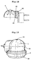
- Figure 19 shows the external aspect of the new diffuser equipment, in one of its possible presentations.
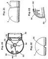
- Figures 20, 21 and 22 represent respective dihedral views of the hemispherical pieces that make up the equipment casing in accordance with figure 1, and figure 23 is a section of the piece itself in a plan view shown by XXIII-XXIII in figure 20.
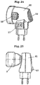
- Figures 24 and 25 show presentations of the respective external shapes of the previous one.
- Figures 26 to 28 show respective versions of volatile liquid evaporator equipment, corresponding to the known background in the previous state of the technique and in respect of which the equipment of this invention shows features of novelty.
- The elements represented by numbers in the figures correspond to the parts stated below.
- The vapour diffuser device object of this patent is basically made up of a body formed by a casing/carcass in which the following are housed: the heating element, the safety device, part of a mechanical regulator mechanism (which has another part protruding), an electronic regulator for the supply to the equipment and the mouth for the container that holds the liquid product destined to be vaporised and the porous wick and diffuser.
- a) The casing/carcass (1) externally has, in the preferred version in accordance with figure 1, an incomplete spherical shape that can be seen in figure 19, coming from a cylindrical mouth (3) for the mechanical regulator, the safety device and the container mouth (2). Likewise, the casing/carcass (1) in the expansion being almost cylindrical (4) which will make contact pins to electricity supply wall socket.
- b) The safety device guarantees that, once the container (2) is
connected to the body of the device by means of an express and complicated
movement that will be described below, the separation of the container is not
feasible without carrying out another complicated express movement.
Making up the safety device:- The element (5) figures 2 and 3 with a cylindrical-angular shape, with the helicoidal screw slot (6) on the inner wall (7), the rim (8), the upper notches (9) and the external step (10);
- The element (11), figures 4 to 7, in the general shape of a plate, completed by the hemispherical part (1) the casing/carcass and involves the following parts:
- c) The container (2), figures 11 and 12, has an external threaded area (27) at its mouth and a support (28) for the cylindrical wick (17), and this occupies an axial position against the previous elements.
- d) The heater element, shown by way of example in figures 13 to 17, is made up of a box (12) in general with a flattened triangular prismatic shape, made up of two semi-boxes (13 and 14), with respective central openings (15 and 16) for the passage of the wick (17), being fitted with at least one of the internal lugs (18) which act as guides for the centring of the wick, and the other opening of the neck (35). The angular metal pieces (19 and 20) are housed in the semi-boxes (13 and 14), making the contacts for the heating element, and between the expansions (21) there is an electro-ceramic block made from a PTC type of material (positive temperature coefficient), which heats up when the current is passed. In the openings (15, 16) of the semi-boxes (13 and 14) the neck (35) is shown respectively and the already mentioned centring lugs (18). The appendixes (21) of the contact pieces are in turn housed in the expansions (22) of the semi-boxes (13, 14), and in the areas (13a and 14a) of these forming notches (23, 24) for the passage of the electrical contacts (25, 26), entering on opposing sides of the box (12) of the heater element.
- f) The electronic regulator, figure 18, is made up of a printed circuit board (49), carrying components (50) which comprises of a timer and activator assembly for the heater electricity supply (12). The board is held between two parallel ribs (62) on the internal side of the piece (4).
- g) The opening (51) figure 19 at the top of the hemispherical part (1) allows the escape of the vapours caused by the heating of the capillary wick and its release into the surrounding space.
- h) The pilot light (52) on the front part of the body of the equipment shows the state of connection to the current and the working of the vapour diffuser.
- i) The hemispherical body (1) of the casing/carcass has female columns (53) on the inside figures 20 to 23 in order to ensure the fitting together of the body with the stems (42) of the heater element (12) (the section can be seen in figure 23), the slot (55) for the pilot light (52), and the cylinder or chimney (64) that shapes the opening (51) of the outlet for the vapours to be released.
- j) The versions in figures 24 and 25, with a different geometric exterior, have a switch on the side (57), side openings (58) for the entry of air and openings (59) at the end for the exit of the vapours generated, placed in the casing/carcass (60 and 61), respectively.
-
- With the elements stated, and with reference to figure 1, the container (2) is fitted into the casing/carcass (1) by the insertion of the wick (17) into the central opening (40) of the element (11) and into the central opening of the heater element (12), and by the introduction of the threaded neck (27) of the container into the cylindrical ring shaped element (5), where the helicoidal screw (6) holds said neck (27).
- The element (5), coaxial with element (11) and with the ring (67) shaped by element (45), is initially detached from both and, hence, can turn freely in them.
- Thus, the container is free to turn in the casing/carcass (1).
- For the effective holding of the container (2), force is applied with a certain degree of intensity in an axial direction and in an upward direction as shown in figure 1, with which the notches (9) of the turning element (5) correspond with the lugs (65) placed on the inner face of the fixed element (11), this (5) becoming momentarily fixed, which allows the screwing of the neck (27) of the container and the effective fixing of same in place, being solidly fixed with the elements (11 and 45).
- The container (2) and the element (5) can now be turned together, being separated (by gravity) from the fixed element (11) due to the exit (separation) of the notches (9) from the element (5) against the lugs (65) of it.
- But the container and the element (5) cannot be separated from the casing/carcass (1) as a result of the element (5) being held by the periphery (step 10).
- When the effective separation of the container (2) is desired, for example after the liquid contained is used up, once again force is applied in an upward axial direction, with which the element (5) is momentarily immobilised in (11) by meeting with the notches (9) and the lugs (65) and the neck (27) can be unscrewed from it (5).
- The safety of the equipment in regard to the possibility of it being meddled with by a child lies in the fact that, normally, he/she will not be able to apply the axial force and the turn necessary on his/her own to be able to separate the neck (27) from its housing, and will only be able, in such situation, to turn the container around on its axis.
- The mechanical graduation of the vapour flow expelled by the equipment is the result of the sliding of the fingers (56) of the rotating element (45) along the protruding curved lines (46) having decreasing heights from the fixed element (11). This varies the axial position of (45) and thus, the element (5) held by the external step (10) on the ring (67), the container (2) being more or less introduced into the opening (27) and consequently the wick (17) in the heater (12) as shown in figures 11 and 12.
- The lugs (63) of the protrusions (46) determine differing positions for the contact of the fingers or appendixes (56) of the revolving element (45), therefore, differing degrees of the introduction of the wick (17) in the heater (12).
Claims (8)
- Electrical equipment for vapour diffusion, being of the type made up of a container (2) holding a product in a liquid state to be evaporated and a diffuser wick (17), movable against an electrical heating element (12) fixed into the casing/carcass (1) of the device, a safety device fitted to a mechanical intensity regulator (45) for the flow of the evaporated product, visual indicator (48) device for the said intensity of the flow and an electronic regulator for the supply to the heater, characterised in that the safety device is functionally coupled to the mechanical regulator device (45) and is made up from:a) A tubular cylindrical element (5) with internal thread,b) A cylindrical-annular element (11) fitted with openings (34) and protrusions (30) surrounding the previous element, andc) A disk shaped element (36) fitted with openings (38, 39, 40) and protrusions (44, 46 and 65) defining in its entirety an operative group that allows for the initial coupling of the container (2) and the wick (17) by means of force in an upward axial direction, the thread of the neck (27) of the container (2) and the retention of the latter with the possibility of free rotational movement in both directions, requiring another upward force to achieve the possibility of separation of the container by unscrewing.
- Electrical equipment for vapour diffusion, in accordance with claim 1, is characterised in that the component (5) of the safety device is made up with the screw thread (6) on its internal face for the attachment of the container (2) of the product to be evaporated, a rim (8) with multiple upper notches (9) and an exterior step (10).
- Electrical equipment for vapour diffusion, in accordance with claim 1, is characterised in that the component (11) of the safety device, in the general shape of a plate, is made up of an upper groove (29), three vertical fingers (30), a lower ring (31) with openings (32), an external oblique area (33) with openings (34) and the cylindrical flap (3) which partially protrudes from the casing/carcass (1).
- Electrical equipment for vapour diffusion, in accordance with claim 1, is characterised in that the element (11) of the safety device has a lateral expansion (37) on its circular (36) part corresponding to the expansion (4) of the case/carcass (1), and has the openings (38) on its upper surface in an arch, the openings (3) in a trapezoidal shape and the central circular opening (40), likewise on its lower side, the protrusions (65) fitted together with the notches (9) of the element (5).
- Electrical equipment for vapour diffusion, in accordance with claim 1, is characterised in that the cylindrical flap (45) of the mechanical regulator device for the intensity flow of the evaporated product, turns on an axis that is in line with the body (1) of the equipment and emerging in respect of same by a length proportional to the rate of the exit flow of the evaporated product, having external means (48), such as lines of differing lengths, marking out the amount of said rate of flow.
- Electrical equipment for vapour diffusion, in accordance with claim 1, is characterised in that the heater device remains housed and fixed in the internal upper part of the casing/carcass (1) by several positioning guides (54).
- Electrical equipment for vapour diffusion, in accordance with claim 1, is characterised in that on the front part of the casing/carcass (1) there is a luminous indicator (52) showing the working state of the device, provided by a light emitting diode (LED).
- Electrical equipment for vapour diffusion, in accordance with claim 1, is characterised in that on the upper part of the casing/carcass (1) there is an opening (51) for the exit of the vaporised product, connected to a chimney tube (64) on the inside.
Applications Claiming Priority (2)
| Application Number | Priority Date | Filing Date | Title |
|---|---|---|---|
| ES200101442 | 2001-06-21 | ||
| ES200101442A ES2185490B1 (en) | 2001-06-21 | 2001-06-21 | STEAM DIFFUSER ELECTRICAL DEVICE. |
Publications (2)
| Publication Number | Publication Date |
|---|---|
| EP1270022A1 EP1270022A1 (en) | 2003-01-02 |
| EP1270022B1 true EP1270022B1 (en) | 2004-09-15 |
Family
ID=8498140
Family Applications (1)
| Application Number | Title | Priority Date | Filing Date |
|---|---|---|---|
| EP20020013690 Expired - Lifetime EP1270022B1 (en) | 2001-06-21 | 2002-06-20 | Electrical vapour diffuser equipment |
Country Status (3)
| Country | Link |
|---|---|
| EP (1) | EP1270022B1 (en) |
| DE (1) | DE60201220T2 (en) |
| ES (2) | ES2185490B1 (en) |
Cited By (4)
| Publication number | Priority date | Publication date | Assignee | Title |
|---|---|---|---|---|
| USD872245S1 (en) | 2018-02-28 | 2020-01-07 | S. C. Johnson & Son, Inc. | Dispenser |
| USD872847S1 (en) | 2018-02-28 | 2020-01-14 | S. C. Johnson & Son, Inc. | Dispenser |
| USD878538S1 (en) | 2018-02-28 | 2020-03-17 | S. C. Johnson & Son, Inc. | Dispenser |
| USD881365S1 (en) | 2018-02-28 | 2020-04-14 | S. C. Johnson & Son, Inc. | Dispenser |
Families Citing this family (15)
| Publication number | Priority date | Publication date | Assignee | Title |
|---|---|---|---|---|
| ES1051930Y (en) * | 2002-05-07 | 2003-02-16 | Llevall Pere Llado | CASE-HOUSING FOR VAPOR DIFFUSER DEVICES. |
| GB2404149A (en) * | 2003-07-18 | 2005-01-26 | Reckitt Benckiser | Portable device for enabling vapour emanation |
| GB2411590A (en) * | 2004-03-06 | 2005-09-07 | Reckitt Benckiser Uk Ltd | Emanator device |
| US7209650B2 (en) | 2004-03-29 | 2007-04-24 | Dbk Espana, S.A. | Method and device for the evaporation of volatile compounds |
| PT1736177E (en) * | 2004-03-29 | 2010-08-24 | Zobele Espana Sa | Method and device for the evaporation of volatile substances |
| US6968124B1 (en) * | 2004-06-25 | 2005-11-22 | S. C. Johnson & Son, Inc. | Electric liquid volatile dispenser |
| CN109715221B (en) * | 2016-06-16 | 2022-10-21 | 赛特奥有限公司 | Device for dispensing, in particular for evaporating, volatile substances, in particular fragrances and/or active agents |
| CN106719512B (en) * | 2016-12-06 | 2022-03-25 | 山东省寄生虫病防治研究所 | Environment-friendly mosquito trapping device |
| USD846724S1 (en) | 2017-10-23 | 2019-04-23 | S. C. Johnson & Son, Inc. | Dispenser |
| USD871226S1 (en) | 2017-10-23 | 2019-12-31 | S. C. Johnson & Son, Inc. | Container |
| USD846725S1 (en) | 2017-10-23 | 2019-04-23 | S. C. Johnson & Son, Inc. | Dispenser |
| USD859163S1 (en) | 2017-10-23 | 2019-09-10 | S. C. Johnson & Son, Inc. | Container with cover |
| USD853548S1 (en) | 2018-05-07 | 2019-07-09 | S. C. Johnson & Son, Inc. | Dispenser |
| USD852938S1 (en) | 2018-05-07 | 2019-07-02 | S. C. Johnson & Son, Inc. | Dispenser |
| CN113244644B (en) * | 2021-05-13 | 2022-07-19 | 安徽科技学院 | Chinese-medicinal material concentrator |
Family Cites Families (7)
| Publication number | Priority date | Publication date | Assignee | Title |
|---|---|---|---|---|
| IT1280407B1 (en) * | 1995-04-06 | 1998-01-20 | Falp Srl | APPARATUS FOR THE VAPORIZATION OF INSECTICIDE OR SIMILAR SOLUTIONS |
| IT240993Y1 (en) * | 1996-11-07 | 2001-04-20 | Zobele Ind Chim | OVEN FOR EVAPORATION WITH ADJUSTABLE INTENSITY OF CHEMICALS |
| ES2137111B1 (en) | 1997-06-24 | 2000-09-16 | Dbk Espana Sa | EVAPORATOR DEVICE FOR VOLATILE PRODUCTS WITH VARIABLE EVAPORATION INTENSITY. |
| ES2163956B2 (en) * | 1998-08-21 | 2003-05-01 | Dbk Espana Sa | EVAPORATOR DEVICE OF VOLATILE PRODUCTS WITH VARIABLE EVAPORATION INTENSITY, BY THE INTERPOSITION OF A MOBILE CAP. |
| ES2160033B1 (en) * | 1999-02-15 | 2002-05-16 | Dbk Espana Sa | SHUTTER FOR CONTAINERS OF EVAPORABLE LIQUIDS. |
| GB2357035A (en) * | 1999-12-06 | 2001-06-13 | Ureig Technologies S A | Electric vapor diffuser device with tamper-proof mechanism |
| IT1318278B1 (en) * | 2000-07-28 | 2003-07-28 | Zobele Ind Chimiche S P A Ora | ELECTRIC VAPORIZER OF INSECTICIDES OR PERFUMES IN LIQUID FORMULATIONS, WITH ADJUSTABLE EVAPORATION INTENSITY. |
-
2001
- 2001-06-21 ES ES200101442A patent/ES2185490B1/en not_active Expired - Lifetime
-
2002
- 2002-06-20 DE DE2002601220 patent/DE60201220T2/en not_active Expired - Lifetime
- 2002-06-20 EP EP20020013690 patent/EP1270022B1/en not_active Expired - Lifetime
- 2002-06-20 ES ES02013690T patent/ES2229019T3/en not_active Expired - Lifetime
Cited By (5)
| Publication number | Priority date | Publication date | Assignee | Title |
|---|---|---|---|---|
| USD872245S1 (en) | 2018-02-28 | 2020-01-07 | S. C. Johnson & Son, Inc. | Dispenser |
| USD872847S1 (en) | 2018-02-28 | 2020-01-14 | S. C. Johnson & Son, Inc. | Dispenser |
| USD878538S1 (en) | 2018-02-28 | 2020-03-17 | S. C. Johnson & Son, Inc. | Dispenser |
| USD880670S1 (en) | 2018-02-28 | 2020-04-07 | S. C. Johnson & Son, Inc. | Overcap |
| USD881365S1 (en) | 2018-02-28 | 2020-04-14 | S. C. Johnson & Son, Inc. | Dispenser |
Also Published As
| Publication number | Publication date |
|---|---|
| DE60201220D1 (en) | 2004-10-21 |
| ES2185490A1 (en) | 2003-04-16 |
| ES2229019T3 (en) | 2005-04-16 |
| ES2185490B1 (en) | 2004-06-16 |
| DE60201220T2 (en) | 2005-10-13 |
| EP1270022A1 (en) | 2003-01-02 |
Similar Documents
| Publication | Publication Date | Title |
|---|---|---|
| EP1270022B1 (en) | Electrical vapour diffuser equipment | |
| AU2005267312B8 (en) | Electric liquid volatile dispenser | |
| US6236807B1 (en) | Wick-based liquid emanation system with child-resistant and miniaturization features | |
| EP1175833B1 (en) | Electric evaporator for insecticides or perfumes in liquid formulation, with adjustable evaporation intensity | |
| US7542664B2 (en) | Vaporizer with night light | |
| US20040247300A1 (en) | Vaporizer features | |
| EP0736248A1 (en) | Apparatus for vaporizing insecticidal solutions and the like | |
| US20020179643A1 (en) | Fragrance emitting device | |
| GB2354445A (en) | Electric air freshener or insecticide device | |
| EP0689766A1 (en) | Apparatus for vaporizing insecticidal solutions and the like | |
| WO2007045832A1 (en) | Air freshener with lighting unit | |
| US20040067172A1 (en) | Air freshener device with child resistant features | |
| KR102055697B1 (en) | Candle combined with diffuser | |
| US8702419B2 (en) | Automated Candle Blower | |
| GB2255167A (en) | Gas candle | |
| US20210213471A1 (en) | Dispenser with a visual indication system | |
| GB2354444A (en) | Device for evaporating volatile liquids | |
| EP4298190A1 (en) | Self-extinguishing candle | |
| GB2356814A (en) | Electric air freshener or insecticide device | |
| JP2002200156A (en) | Heated steam fog generator | |
| JPH04103479U (en) | Heating evaporation device |
Legal Events
| Date | Code | Title | Description |
|---|---|---|---|
| PUAI | Public reference made under article 153(3) epc to a published international application that has entered the european phase |
Free format text: ORIGINAL CODE: 0009012 |
|
| AK | Designated contracting states |
Kind code of ref document: A1 Designated state(s): AT BE CH CY DE DK ES FI FR GB GR IE IT LI LU MC NL PT SE TR |
|
| AX | Request for extension of the european patent |
Free format text: AL;LT;LV;MK;RO;SI |
|
| AKX | Designation fees paid | ||
| 17P | Request for examination filed |
Effective date: 20030808 |
|
| RBV | Designated contracting states (corrected) |
Designated state(s): BE DE ES FR GB NL |
|
| REG | Reference to a national code |
Ref country code: DE Ref legal event code: 8566 |
|
| GRAP | Despatch of communication of intention to grant a patent |
Free format text: ORIGINAL CODE: EPIDOSNIGR1 |
|
| RAP1 | Party data changed (applicant data changed or rights of an application transferred) |
Owner name: BLAU BARCELONESA D'ACTIVITATS COMERCIALS, S.A. |
|
| GRAS | Grant fee paid |
Free format text: ORIGINAL CODE: EPIDOSNIGR3 |
|
| GRAA | (expected) grant |
Free format text: ORIGINAL CODE: 0009210 |
|
| AK | Designated contracting states |
Kind code of ref document: B1 Designated state(s): BE DE ES FR GB NL |
|
| REG | Reference to a national code |
Ref country code: GB Ref legal event code: FG4D |
|
| REG | Reference to a national code |
Ref country code: IE Ref legal event code: FG4D |
|
| REF | Corresponds to: |
Ref document number: 60201220 Country of ref document: DE Date of ref document: 20041021 Kind code of ref document: P |
|
| RAP2 | Party data changed (patent owner data changed or rights of a patent transferred) |
Owner name: ZOBELE HOLDING SPA |
|
| REG | Reference to a national code |
Ref country code: GB Ref legal event code: 732E |
|
| NLT2 | Nl: modifications (of names), taken from the european patent patent bulletin |
Owner name: ZOBELE HOLDING SPA |
|
| REG | Reference to a national code |
Ref country code: ES Ref legal event code: FG2A Ref document number: 2229019 Country of ref document: ES Kind code of ref document: T3 |
|
| PLBE | No opposition filed within time limit |
Free format text: ORIGINAL CODE: 0009261 |
|
| STAA | Information on the status of an ep patent application or granted ep patent |
Free format text: STATUS: NO OPPOSITION FILED WITHIN TIME LIMIT |
|
| NLS | Nl: assignments of ep-patents |
Owner name: ZOBELE HOLDING SPA |
|
| ET | Fr: translation filed | ||
| 26N | No opposition filed |
Effective date: 20050616 |
|
| NLS | Nl: assignments of ep-patents |
Owner name: DH SUMMER S.P.A. Effective date: 20081105 |
|
| NLT1 | Nl: modifications of names registered in virtue of documents presented to the patent office pursuant to art. 16 a, paragraph 1 |
Owner name: ZOBELE HOLDING S.P.A. |
|
| PGFP | Annual fee paid to national office [announced via postgrant information from national office to epo] |
Ref country code: BE Payment date: 20100611 Year of fee payment: 9 |
|
| BERE | Be: lapsed |
Owner name: DH SUMMER SPA Effective date: 20110630 |
|
| PG25 | Lapsed in a contracting state [announced via postgrant information from national office to epo] |
Ref country code: BE Free format text: LAPSE BECAUSE OF NON-PAYMENT OF DUE FEES Effective date: 20110630 |
|
| REG | Reference to a national code |
Ref country code: FR Ref legal event code: PLFP Year of fee payment: 15 |
|
| REG | Reference to a national code |
Ref country code: FR Ref legal event code: PLFP Year of fee payment: 16 |
|
| PGFP | Annual fee paid to national office [announced via postgrant information from national office to epo] |
Ref country code: DE Payment date: 20170523 Year of fee payment: 16 |
|
| PGFP | Annual fee paid to national office [announced via postgrant information from national office to epo] |
Ref country code: NL Payment date: 20170602 Year of fee payment: 16 |
|
| REG | Reference to a national code |
Ref country code: FR Ref legal event code: PLFP Year of fee payment: 17 |
|
| REG | Reference to a national code |
Ref country code: DE Ref legal event code: R119 Ref document number: 60201220 Country of ref document: DE |
|
| REG | Reference to a national code |
Ref country code: NL Ref legal event code: MM Effective date: 20180701 |
|
| PG25 | Lapsed in a contracting state [announced via postgrant information from national office to epo] |
Ref country code: NL Free format text: LAPSE BECAUSE OF NON-PAYMENT OF DUE FEES Effective date: 20180701 |
|
| PG25 | Lapsed in a contracting state [announced via postgrant information from national office to epo] |
Ref country code: DE Free format text: LAPSE BECAUSE OF NON-PAYMENT OF DUE FEES Effective date: 20190101 |
|
| PGFP | Annual fee paid to national office [announced via postgrant information from national office to epo] |
Ref country code: FR Payment date: 20190614 Year of fee payment: 18 |
|
| PGFP | Annual fee paid to national office [announced via postgrant information from national office to epo] |
Ref country code: GB Payment date: 20190614 Year of fee payment: 18 Ref country code: ES Payment date: 20190709 Year of fee payment: 18 |
|
| GBPC | Gb: european patent ceased through non-payment of renewal fee |
Effective date: 20200620 |
|
| PG25 | Lapsed in a contracting state [announced via postgrant information from national office to epo] |
Ref country code: FR Free format text: LAPSE BECAUSE OF NON-PAYMENT OF DUE FEES Effective date: 20200630 Ref country code: GB Free format text: LAPSE BECAUSE OF NON-PAYMENT OF DUE FEES Effective date: 20200620 |
|
| REG | Reference to a national code |
Ref country code: ES Ref legal event code: FD2A Effective date: 20211103 |
|
| PG25 | Lapsed in a contracting state [announced via postgrant information from national office to epo] |
Ref country code: ES Free format text: LAPSE BECAUSE OF NON-PAYMENT OF DUE FEES Effective date: 20200621 |